air condition Hyundai Accent 2010 Owner's Manual
[x] Cancel search | Manufacturer: HYUNDAI, Model Year: 2010, Model line: Accent, Model: Hyundai Accent 2010Pages: 284, PDF Size: 10.23 MB
Page 9 of 284
F9
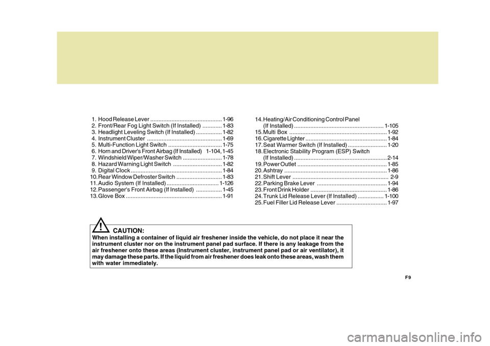
1. Hood
Release Lever ............................................ 1-96
2. Front/Rear Fog Light Switch (If Installed) ............ 1-83
3. Headlight Leveling Switch (If Installed) ................ 1-82
4. Instrument Cluster.............................................. 1-69
5. Multi-Function Light Switch................................. 1-75
6. Horn and Driver's Front Airbag (If Installed) 1-104, 1-45
7. Windshield W iper/Washer Switch ........................1-78
8. Hazard Warning Light Switch.............................. 1-82
9. Digital Clock ........................................................ 1-84
10. Rear Window De froster Switch ............................ 1-83
11. Audio System (If Installed) ................................ 1-126
12. Passenger's Front Airbag (If Installed) ................1-45
13. Glov e Box ........................................................... 1-91
CAUTION:
When installing a container of liquid air freshener inside the vehicle, do not place it near the instrument cluster nor on the instrument panel pad surface. If there is any leakage from the air freshener onto these areas (Instrument cluster, instrument panel pad or air ventilator), itmay damage these parts. If the liquid from air freshener does leak onto these areas, wash them with water immediately.
! 14. Heating/Air Conditioning Control Panel
(If Installed) ....................................................... 1-105
15. Multi Box ............................................................ 1-92
16. Cigarette Lighter .................................................. 1-84
17. Seat Warmer Switch (If Installed) ........................ 1-20
18. Electronic Stability Program (ESP) Switch
(If Installed) ......................................................... 2-14
19. Power Outlet ....................................................... 1-85
20. Ashtray ............................................................... 1-86
21. Shift Lever ........................................................... 2-9
22. Parking Brake Lever ........................................... 1-94
23. Front Drink Holder ............................................... 1-86
24. Trunk Lid Release Lever (If Installed) ................1-100
25. Fuel Filler Lid Release Lever ...............................1-97
Page 11 of 284
F11
CAUTION:
When installing a container of liquid air freshener inside the vehicle, do not place it near the instrument cluster nor on the instrument panel pad surface. If there is any leakage from the air freshener onto these areas (Instrument cluster, instrument panel pad or air ventilator), it may damage these parts. If the liquid from air freshener does leak onto these areas, wash themwith water immediately.
!
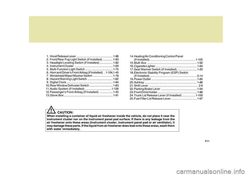
1. Hood
Release Lever ............................................ 1-96
2. Front/Rear Fog Light Switch (If Installed) ............ 1-83
3. Headlight Leveling Switch (If Installed) ................ 1-82
4. Instrument Cluster.............................................. 1-69
5. Multi-Function Light Switch................................. 1-75
6. Horn and Driver's Front Airbag (If Installed) . 1-104,1-45
7. Windshield W iper/Washer Switch ........................1-78
8. Hazard Warning Light Switch.............................. 1-82
9. Digital Clock ........................................................ 1-84
10. Rear Window De froster Switch ............................ 1-83
11. Audio System (If Installed) ................................ 1-126
12. Passenger's Front Airbag (If Installed) ................1-45
13. Glov e Box ........................................................... 1-9114. Heating/Air Conditioning Control Panel
(If Installed) ....................................................... 1-105
15. Multi Box ............................................................ 1-92
16. Cigarette Lighter .................................................. 1-84
17. Seat Warmer Switch (If Installed) ........................ 1-20
18. Electronic Stability Program (ESP) Switch (If Installed) ......................................................... 2-14
19. Power Outlet ....................................................... 1-85
20. Ashtray ............................................................... 1-86
21. Shift Lever ........................................................... 2-9
22. Parking Brake Lever ........................................... 1-94
23. Front Drink Holder ............................................... 1-86
24. Trunk Lid Release Lever (If Installed) ................1-100
25. Fuel Filler Lid Release Lever ...............................1-97
Page 54 of 284
1FEATURES OF YOUR HYUNDAI
42
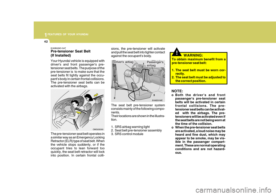
The seat belt pre-tensioner system consists mainly of the following compo- nents.Their locations are shown in the illustra- tion.
1. SRS airbag warning light
2. Seat belt pre-tensioner assembly
3. SRS control module
Passenger's airbag
B180D01MC
Driver's airbag1
2 3
sions, the pre-tensioner will activate and pull the seat belt into tighter contactagainst the occupant's body.
OMG035300
B180B02MC-GAT Pre-tensioner Seat Belt (If Installed) Your Hyundai vehicle is equipped with driver's and front passenger's pre-tensioner seat belts. The purpose of the pre-tensioner is to make sure that the seat belts fit tightly against the occu-pant's body in certain frontal collisions. The pre-tensioner seat belts can be activated with the airbags.
The pre-tensioner seat belt operates ina similar way as an Emergency Locking Retractor (ELR) type of seat belt. When the vehicle stops suddenly, or if theoccupant tries to lean forward too quickly, the seat belt retractor will lock into position. In certain frontal colli-
!WARNING:
To obtain maximum benefit from a pre-tensioner seat belt:
1. The seat belt must be worn cor- rectly.
2. The seat belt must be adjusted to the correct position.
NOTE:
o Both the driver's and front passenger's pre-tensioner seat belts will be activated in certainfrontal collisions. The pre- tensioner seat belts can be activat- ed with the airbags. The pre-tensioners will be activated even if the seat belts are not being worn at the time of the collision.
o When the pre-tensioner seat belts are activated, a loud noise may beheard and fine dust, which mayappear to be smoke, may be vis- ible in the passenger compart- ment. These are normal operatingconditions and are not hazard- ous.
Page 57 of 284
1
FEATURES OF YOUR HYUNDAI
45
B240A01MC
Driver's Front Airbag
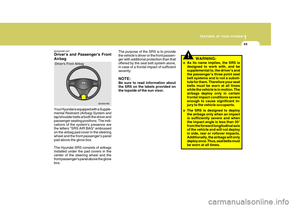
Your Hyundai is equipped with a Supple- mental Restraint (Airbag) System and lap/shoulder belts at both the driver and passenger seating positions. The indi-cations of the system's presence are the letters "SRS AIR BAG" embossed on the airbag pad cover in the steeringwheel and the front passenger's panel pad above the glove box. The Hyundai SRS consists of airbags installed under the pad covers in the center of the steering wheel and thefront passenger's panel above the glove box. B240A02NF-GAT Driver's and Passenger's Front Airbag
!
The purpose of the SRS is to provide the vehicle's driver or the front passen-ger with additional protection than that offered by the seat belt system alone, in case of a frontal impact of sufficientseverity. NOTE: Be sure to read information about the SRS on the labels provided onthe topside of the sun visor.
WARNING:
o As its name implies, the SRS is designed to work with, and besupplemental to, the driver's and the passenger's three point seat belt systems and is not a substi-tute for them. Therefore your seat belts must be worn at all times while the vehicle is in motion. Theairbags deploy only in certain frontal impact conditions severe enough to cause significant in-jury to the vehicle occupants.
o The SRS is designed to deploy the airbags only when an impact is sufficiently severe and when the impact angle is less than 30°from the forward longitudinal axis of the vehicle and will not deploy in side, rear or rollover impacts.Additionally, the airbags will only deploy once. Thus, seat belts must be worn at all times.
Page 60 of 284
1FEATURES OF YOUR HYUNDAI
48
!WARNING:
o When the SRS is activated, there may be a loud noise and fine dust will be released throughout the vehicle. These conditions are nor- mal and are not hazardous. How-ever, the fine dust generated dur- ing airbag deployment may cause skin irritation. Wash your handsand face thoroughly with lukewarm water and a mild soap after an accident in which the airbags weredeployed.
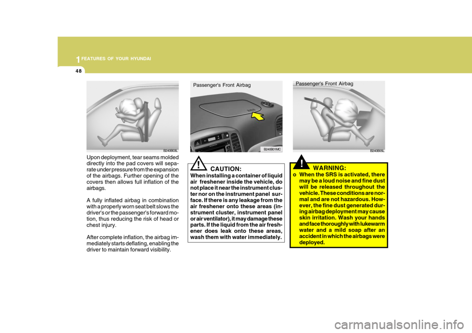
Passenger's Front Airbag
B240B05L
!CAUTION:
When installing a container of liquid air freshener inside the vehicle, do not place it near the instrument clus- ter nor on the instrument panel sur-face. If there is any leakage from the air freshener onto these areas (in- strument cluster, instrument panelor air ventilator), it may damage these parts. If the liquid from the air fresh- ener does leak onto these areas,wash them with water immediately.
Passenger's Front Airbag
B240B01MC
Upon deployment, tear seams molded directly into the pad covers will sepa- rate under pressure from the expansionof the airbags. Further opening of the covers then allows full inflation of the airbags. A fully inflated airbag in combination with a properly worn seat belt slows thedriver's or the passenger's forward mo- tion, thus reducing the risk of head or chest injury. After complete inflation, the airbag im- mediately starts deflating, enabling thedriver to maintain forward visibility.B240B03L
Page 64 of 284
1FEATURES OF YOUR HYUNDAI
52
!o Use of seat covers could reduce or
prevent the effectiveness of the system.
o Do not install any accessories on the side or near the side impactairbag.
o Do not use excessive force on the side of the seat.
o Do not place any objects over the
airbag or between the airbag and yourself.
o Do not place any objects (an um-
brella, bag, etc.) between the frontdoor and the front seat. Such ob- jects may become dangerous pro-jectiles and cause injury if the supplemental side impact airbag inflates.
o To prevent unexpected deploy- ment of the side impact air bagthat may result in personal injury,avoid impact to the side impact airbag sensor when the ignition key is on.
WARNING:
o The side impact airbag is supple- mental to the driver's and the passenger's seat belt systems and is not a substitute for them. There-fore your seat belts must be worn at all times while the vehicle is in motion.The airbags deploy only in certain side impact conditions severe enough to cause significant injuryto the vehicle occupants.
o For best protection from the side
impact airbag system and to avoid being injured by the deploying side impact airbag, both front seatoccupants should sit in an upright position with the seat belt proper- ly fastened. The driver's handsshould be placed on the steering wheel at the 9:00 and 3:00 o'clock positions. The passenger's armsand hands should be placed on their laps.
o Do not use any accessory seat covers.
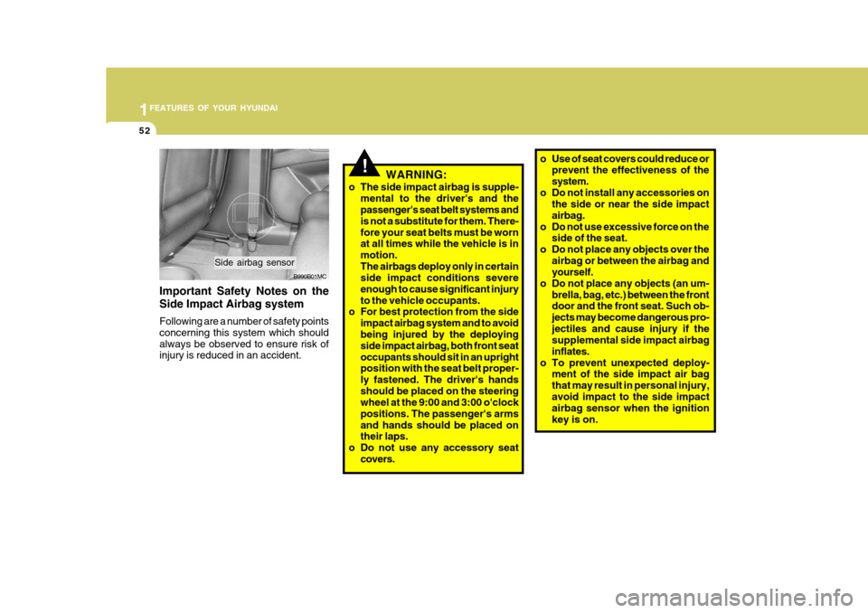
B990B01MC
Side airbag sensor
Important Safety Notes on the Side Impact Airbag system Following are a number of safety points concerning this system which shouldalways be observed to ensure risk of injury is reduced in an accident.
Page 80 of 284
1FEATURES OF YOUR HYUNDAI
68
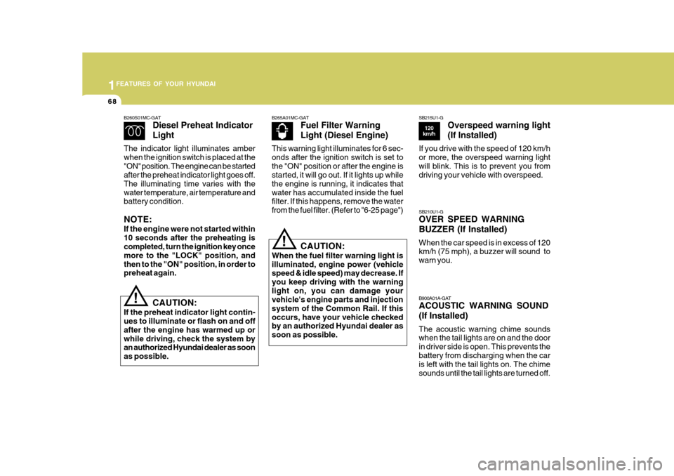
B265A01MC-GATFuel Filter Warning Light (Diesel Engine)
This warning light illuminates for 6 sec- onds after the ignition switch is set tothe "ON" position or after the engine is started, it will go out. If it lights up while the engine is running, it indicates thatwater has accumulated inside the fuel filter. If this happens, remove the water from the fuel filter. (Refer to "6-25 page")
B260S01MC-GAT
Diesel Preheat Indicator Light
The indicator light illuminates amber when the ignition switch is placed at the"ON" position. The engine can be started after the preheat indicator light goes off. The illuminating time varies with thewater temperature, air temperature and battery condition. NOTE: If the engine were not started within 10 seconds after the preheating is completed, turn the ignition key once more to the "LOCK" position, andthen to the "ON" position, in order to preheat again.
! CAUTION:
If the preheat indicator light contin- ues to illuminate or flash on and off after the engine has warmed up orwhile driving, check the system by an authorized Hyundai dealer as soon as possible.
! CAUTION:
When the fuel filter warning light is illuminated, engine power (vehicle speed & idle speed) may decrease. If you keep driving with the warninglight on, you can damage your vehicle's engine parts and injection system of the Common Rail. If thisoccurs, have your vehicle checked by an authorized Hyundai dealer as soon as possible. B900A01A-GAT ACOUSTIC WARNING SOUND (If Installed) The acoustic warning chime sounds when the tail lights are on and the door in driver side is open. This prevents thebattery from discharging when the car is left with the tail lights on. The chime sounds until the tail lights are turned off.
SB210U1-G OVER SPEED WARNING BUZZER (If Installed) When the car speed is in excess of 120 km/h (75 mph), a buzzer will sound to warn you.
SB215U1-G
Overspeed warning light (If Installed)
If you drive with the speed of 120 km/h or more, the overspeed warning lightwill blink. This is to prevent you from driving your vehicle with overspeed.
120
km/h
Page 118 of 284
1FEATURES OF YOUR HYUNDAI
106
This is used to select fresh outside air or recirculating inside air.FreshRecirculation
With the "
" mode selected, air en-
ters the vehicle from outside and is heated or cooled according to the other functions selected. With the "
" mode selected, air from
within the passenger compartment is drawn through the heating system and heated or cooled according to the otherfunctions selected.
HEATING AND VENTILATION
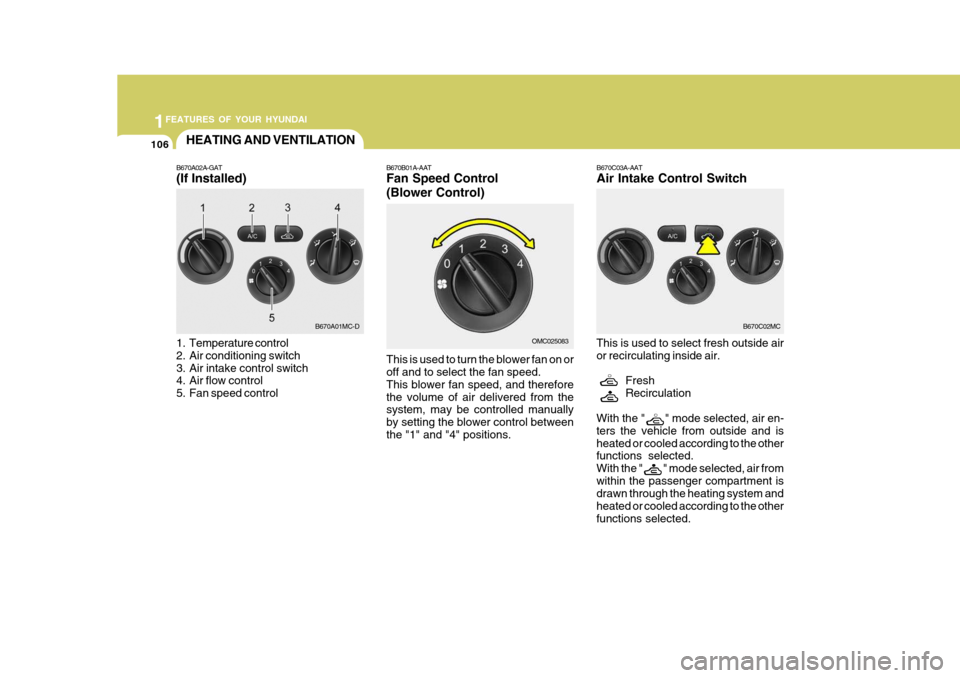
B670A02A-GAT
(If Installed)
1. Temperature control
2. Air conditioning switch
3. Air intake control switch
4. Air flow control
5. Fan speed control B670B01A-AAT Fan Speed Control (Blower Control) This is used to turn the blower fan on or off and to select the fan speed. This blower fan speed, and thereforethe volume of air delivered from the system, may be controlled manually by setting the blower control betweenthe "1" and "4" positions. B670C03A-AAT Air Intake Control Switch
B670A01MC-D
OMC025083B670C02MC
Page 121 of 284
1
FEATURES OF YOUR HYUNDAI
109109109
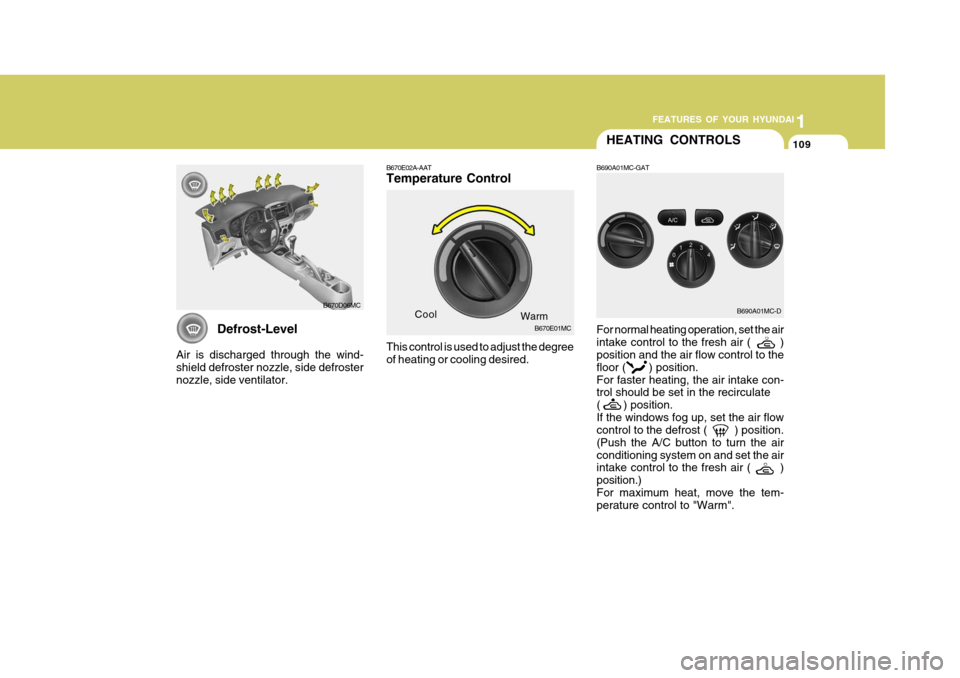
Defrost-Level
Air is discharged through the wind- shield defroster nozzle, side defrosternozzle, side ventilator.
B670D06MC
HEATING CONTROLS
B690A01MC-GAT
B670E02A-AAT Temperature Control This control is used to adjust the degree of heating or cooling desired. For normal heating operation, set the air intake control to the fresh air ( ) position and the air flow control to the floor ( ) position.For faster heating, the air intake con- trol should be set in the recirculate ( ) position.If the windows fog up, set the air flow control to the defrost ( ) position. (Push the A/C button to turn the airconditioning system on and set the air intake control to the fresh air ( ) position.)For maximum heat, move the tem- perature control to "Warm".
Cool
Warm
B670E01MC B690A01MC-D
Page 122 of 284
1FEATURES OF YOUR HYUNDAI
110DEFROSTING/DEFOGGINGVENTILATION
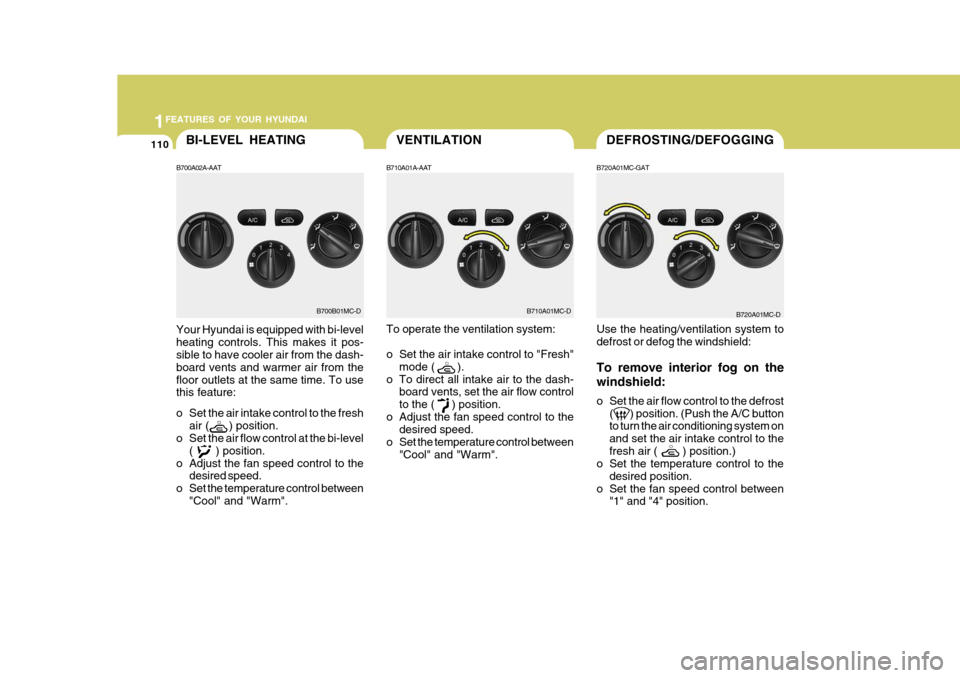
B720A01MC-GAT Use the heating/ventilation system to defrost or defog the windshield: To remove interior fog on the windshield:
o Set the air flow control to the defrost(
) position. (Push the A/C button
to turn the air conditioning system on and set the air intake control to thefresh air ( ) position.)
o Set the temperature control to the
desired position.
o Set the fan speed control between "1" and "4" position.
B710A01A-AAT
To operate the ventilation system:
o Set the air intake control to "Fresh"
mode ( ).
o To direct all intake air to the dash- board vents, set the air flow control to the (
) position.
o Adjust the fan speed control to the desired speed.
o Set the temperature control between "Cool" and "Warm".
B710A01MC-D B720A01MC-D
BI-LEVEL HEATING
B700A02A-AAT
Your Hyundai is equipped with bi-level heating controls. This makes it pos- sible to have cooler air from the dash- board vents and warmer air from thefloor outlets at the same time. To use this feature:
o Set the air intake control to the fresh air ( ) position.
o Set the air flow control at the bi-level
( ) position.
o Adjust the fan speed control to the desired speed.
o Set the temperature control between "Cool" and "Warm".
B700B01MC-D