relay Hyundai Accent 2017 Owner's Manual
[x] Cancel search | Manufacturer: HYUNDAI, Model Year: 2017, Model line: Accent, Model: Hyundai Accent 2017Pages: 380, PDF Size: 12.45 MB
Page 99 of 380
4-25
Features of your vehicle
✽
✽NOTICE
The following symptoms may occur dur-
ing normal vehicle operation:
• The EPS warning light does not illu-
minate.
• The steering gets heavy immediately after turning the ignition switch on.
This happens as the system performs
the EPS system diagnostics. When the
diagnostics is completed, the steering
wheel will return to its normal condi-
tion.
• A click noise may be heard from the EPS relay after the ignition switch is
turned to the ON or LOCK (OFF)
position.
• A motor noise may be heard when the vehicle is at a stop or at a low driving
speed.
• If the Electric Power Steering System does not operate normally, the warning
light will illuminate on the instrument
cluster. The steering wheel may become
difficult to operate due to increasing
steering effort. Take your vehicle to an
authorized HYUNDAI dealer and have
the vehicle checked as soon as possible.
• When you operate the steering wheel in low temperature, abnormal noise
could occur. If temperature rises, the
noise will disappear. This is a normal
condition. (Continued)(Continued)
• When the charging system warning
light comes on or the voltage is low
(When the alternator (or battery) does
not operate normally or it malfunc-
tions), the steering wheel may get
heavy and become difficult to operate
due to increased steering effort.
Tilt and telescopic steering
(if equipped)
Tilt and telescopic steering allows you to
adjust the steering wheel before you
drive. You can also raise it to give your
legs more room when you exit and enter
the vehicle.
The steering wheel should be positioned
so that it is comfortable for you to drive,
while permitting you to see the instru-
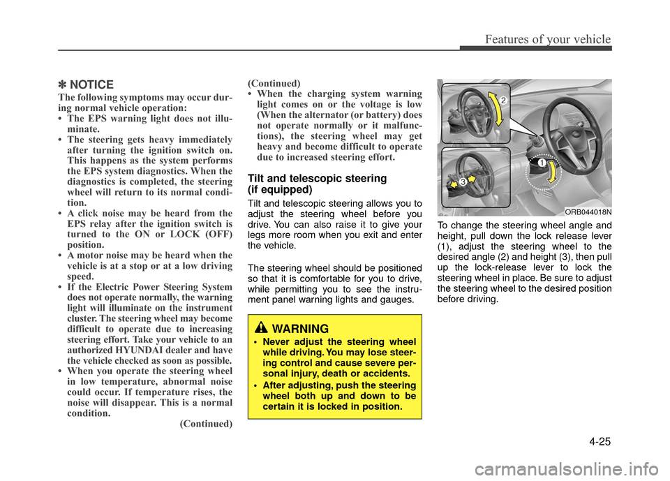
ment panel warning lights and gauges. To change the steering wheel angle and
height, pull down the lock release lever
(1), adjust the steering wheel to the
desired angle (2) and height (3), then pull
up the lock-release lever to lock the
steering wheel in place. Be sure to adjust
the steering wheel to the desired position
before driving.ORB044018N
WARNING
Never adjust the steering wheel
while driving. You may lose steer-
ing control and cause severe per-
sonal injury, death or accidents.
After adjusting, push the steering wheel both up and down to be
certain it is locked in position.
Page 334 of 380
7-51
Maintenance
✽
✽NOTICE
The actual fuse/relay panel label may
differ from equipped items.
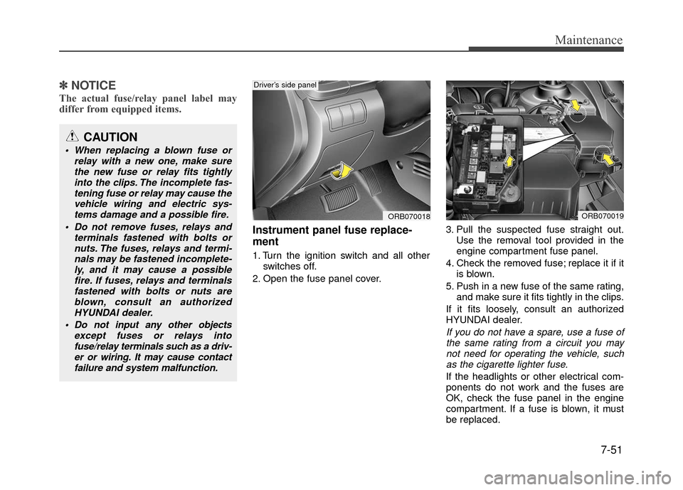
Instrument panel fuse replace-
ment
1. Turn the ignition switch and all other
switches off.
2. Open the fuse panel cover. 3. Pull the suspected fuse straight out.
Use the removal tool provided in the
engine compartment fuse panel.
4. Check the removed fuse; replace it if it is blown.
5. Push in a new fuse of the same rating, and make sure it fits tightly in the clips.
If it fits loosely, consult an authorized
HYUNDAI dealer.
If you do not have a spare, use a fuse of the same rating from a circuit you maynot need for operating the vehicle, suchas the cigarette lighter fuse.
If the headlights or other electrical com-
ponents do not work and the fuses are
OK, check the fuse panel in the engine
compartment. If a fuse is blown, it must
be replaced.
CAUTION
When replacing a blown fuse or relay with a new one, make surethe new fuse or relay fits tightlyinto the clips. The incomplete fas-tening fuse or relay may cause the vehicle wiring and electric sys-tems damage and a possible fire.
Do not remove fuses, relays and terminals fastened with bolts ornuts. The fuses, relays and termi-nals may be fastened incomplete-ly, and it may cause a possiblefire. If fuses, relays and terminalsfastened with bolts or nuts areblown, consult an authorizedHYUNDAI dealer.
Do not input any other objects except fuses or relays intofuse/relay terminals such as a driv-er or wiring. It may cause contactfailure and system malfunction.
ORB070018
Driver’s side panel
ORB070019
Page 337 of 380
Maintenance
7-54
Fuse/relay panel description
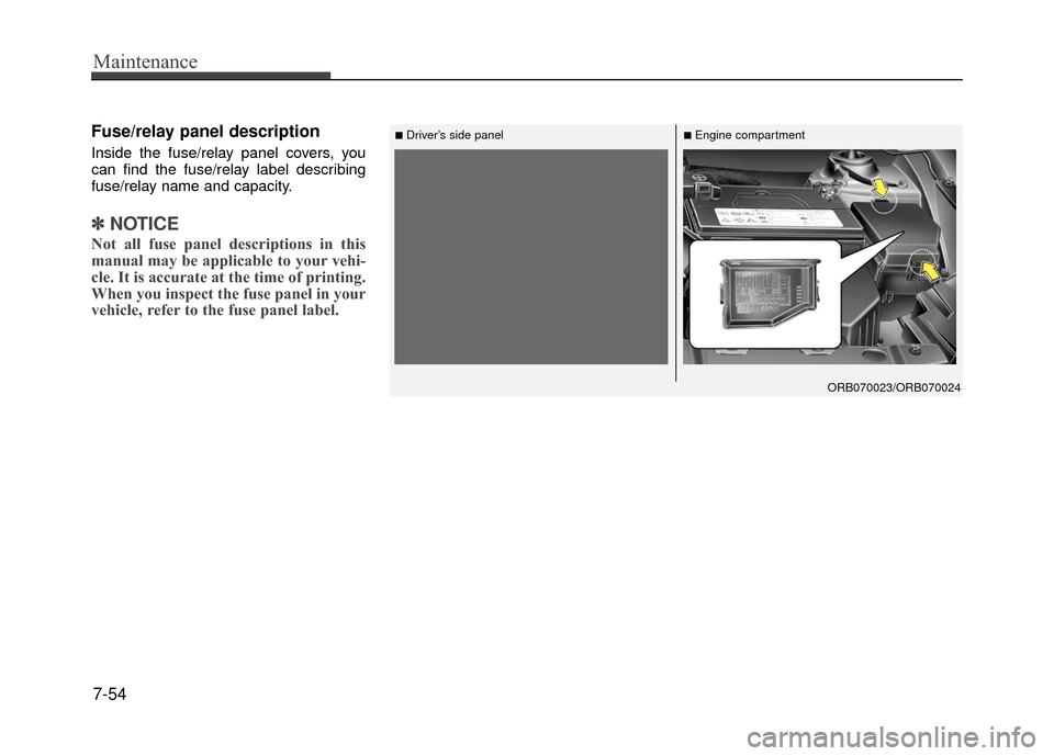
Inside the fuse/relay panel covers, you
can find the fuse/relay label describing
fuse/relay name and capacity.
✽ ✽NOTICE
Not all fuse panel descriptions in this
manual may be applicable to your vehi-
cle. It is accurate at the time of printing.
When you inspect the fuse panel in your
vehicle, refer to the fuse panel label.
■Driver’s side panel■Engine compartment
ORB070023/ORB070024
Page 339 of 380
Maintenance
7-56
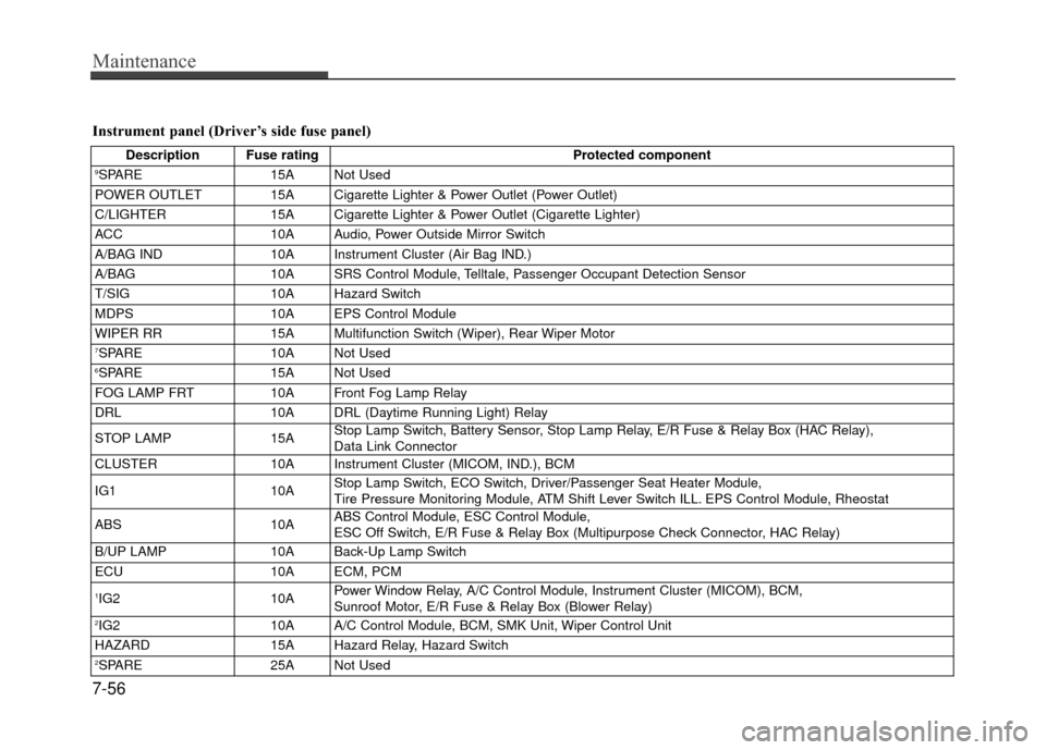
Instrument panel (Driver’s side fuse panel)
Description Fuse ratingProtected component9SPARE15A Not Used
POWER OUTLET 15A Cigarette Lighter & Power Outlet (Power Outlet)
C/LIGHTER 15A Cigarette Lighter & Power Outlet (Cigarette Lighter)
ACC 10A Audio, Power Outside Mirror Switch
A/BAG IND 10A Instrument Cluster (Air Bag IND.)
A/BAG 10A SRS Control Module, Telltale, Passenger Occupant Detection Sensor
T/SIG 10A Hazard Switch
MDPS 10A EPS Control Module
WIPER RR 15A Multifunction Switch (Wiper), Rear Wiper Motor
7SPARE10A Not Used6SPARE 15A Not Used
FOG LAMP FRT 10A Front Fog Lamp Relay
DRL 10A DRL (Daytime Running Light) Relay
STOP LAMP 15AStop Lamp Switch, Battery Sensor, Stop Lamp Relay, E/R Fuse & Relay Box (HAC Relay),
Data Link Connector
CLUSTER 10A Instrument Cluster (MICOM, IND.), BCM
IG1 10AStop Lamp Switch, ECO Switch, Driver/Passenger Seat Heater Module,
Tire Pressure Monitoring Module, ATM Shift Lever Switch ILL. EPS Control Module, Rheostat
ABS 10AABS Control Module, ESC Control Module,
ESC Off Switch, E/R Fuse & Relay Box (Multipurpose Check Connector, HAC Relay)
B/UP LAMP 10A Back-Up Lamp Switch
ECU 10A ECM, PCM
1IG210APower Window Relay, A/C Control Module, Instrument Cluster (MICOM), BCM,
Sunroof Motor, E/R Fuse & Relay Box (Blower Relay)
2IG2
10A A/C Control Module, BCM, SMK Unit, Wiper Control Unit
HAZARD 15A Hazard Relay, Hazard Switch
2SPARE25A Not Used
Page 340 of 380
7-57
Maintenance
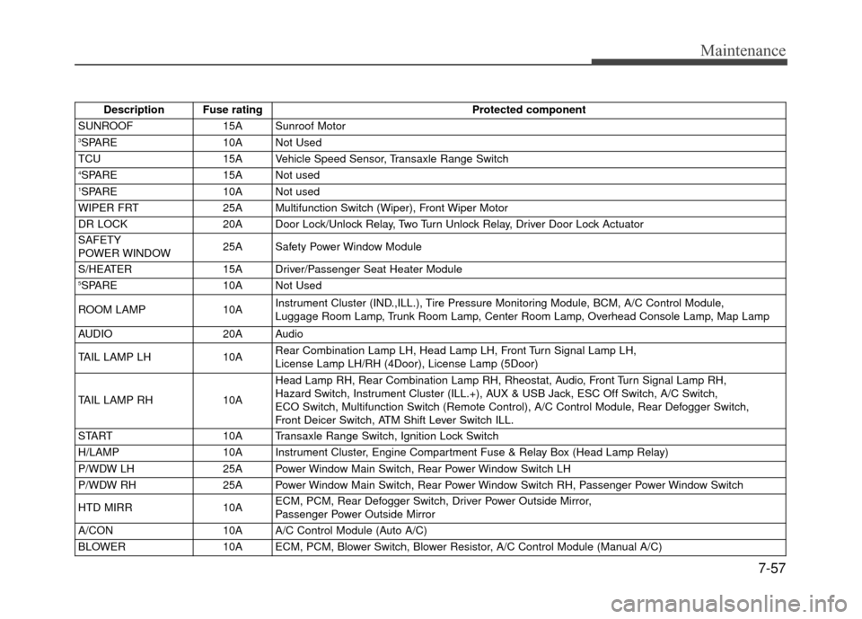
Description Fuse ratingProtected component
SUNROOF 15A Sunroof Motor
3SPARE10A Not Used
TCU 15A Vehicle Speed Sensor, Transaxle Range Switch
4SPARE15A Not used1SPARE10A Not used
WIPER FRT 25A Multifunction Switch (Wiper), Front Wiper Motor
DR LOCK 20A Door Lock/Unlock Relay, Two Turn Unlock Relay, Driver Door Lock Actuator
SAFETY
POWER WINDOW 25A Safety Power Window Module
S/HEATER 15A Driver/Passenger Seat Heater Module
5SPARE10A Not Used
ROOM LAMP 10AInstrument Cluster (IND.,ILL.), Tire Pressure Monitoring Module, BCM, A/C Control Module,
Luggage Room Lamp, Trunk Room Lamp, Center Room Lamp, Overhead Console Lamp, Map Lamp
AUDIO 20A Audio
TAIL LAMP LH 10ARear Combination Lamp LH, Head Lamp LH, Front Turn Signal Lamp LH,
License Lamp LH/RH (4Door), License Lamp (5Door)
TAIL LAMP RH 10AHead Lamp RH, Rear Combination Lamp RH, Rheostat, Audio, Front Turn Signal Lamp RH,
Hazard Switch, Instrument Cluster (ILL.+), AUX & USB Jack, ESC Off Switch, A/C Switch,
ECO Switch, Multifunction Switch (Remote Control), A/C Control Module, Rear Defogger Switch,
Front Deicer Switch, ATM Shift Lever Switch ILL.
START 10A Transaxle Range Switch, Ignition Lock Switch
H/LAMP 10A Instrument Cluster, Engine Compartment Fuse & Relay Box (Head Lamp Relay)
P/WDW LH 25A Power Window Main Switch, Rear Power Window Switch LH
P/WDW RH 25A Power Window Main Switch, Rear Power Window Switch RH, Passenger Power Window Switch
HTD MIRR 10AECM, PCM, Rear Defogger Switch, Driver Power Outside Mirror,
Passenger Power Outside Mirror
A/CON 10A A/C Control Module (Auto A/C)
BLOWER 10A ECM, PCM, Blower Switch, Blower Resistor, A/C Control Module (Manual A/C)
Page 342 of 380
7-59
Maintenance
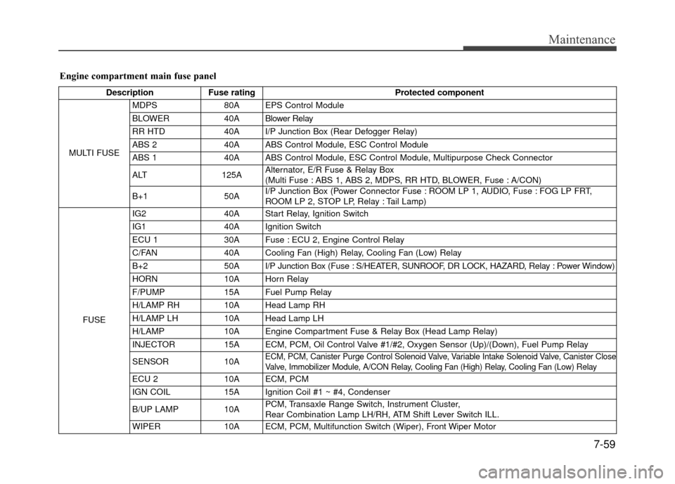
Engine compartment main fuse panel
DescriptionFuse rating Protected component
MULTI FUSE MDPS
80A EPS Control Module
BLOWER 40A Blower Relay
RR HTD 40A I/P Junction Box (Rear Defogger Relay)
ABS 2 40A ABS Control Module, ESC Control Module
ABS 1 40A ABS Control Module, ESC Control Module, Multipurpose Check Connector
ALT 125AAlternator, E/R Fuse & Relay Box
(Multi Fuse : ABS 1, ABS 2, MDPS, RR HTD, BLOWER, Fuse : A/CON)
B+1 50AI/P Junction Box (Power Connector Fuse : ROOM LP 1, AUDIO, Fuse : FOG LP FRT,
ROOM LP 2, STOP LP, Relay : Tail Lamp)
FUSE
IG240AStart Relay, Ignition Switch
IG140AIgnition Switch
ECU 1 30A Fuse : ECU 2, Engine Control Relay
C/FAN 40A Cooling Fan (High) Relay, Cooling Fan (Low) Relay
B+2 50A I/P Junction Box (Fuse : S/HEATER, SUNROOF, DR LOCK, HAZARD, Relay : Power Window)
HORN 10A Horn Relay
F/PUMP 15A Fuel Pump Relay
H/LAMP RH 10A Head Lamp RH
H/LAMP LH 10A Head Lamp LH
H/LAMP 10A Engine Compartment Fuse & Relay Box (Head Lamp Relay)
INJECTOR 15A ECM, PCM, Oil Control Valve #1/#2, Oxygen Sensor (Up)/(Down), Fuel Pump Relay
SENSOR 10A
ECM, PCM, Canister Purge Control Solenoid Valve, Variable Intake Solenoid Valve, Canister Close
Valve, Immobilizer Module, A/CON Relay, Cooling Fan (High) Relay, Cooling Fan (Low) Relay
ECU 210A ECM, PCM
IGN COIL 15A Ignition Coil #1 ~ #4, Condenser
B/UP LAMP 10APCM, Transaxle Range Switch, Instrument Cluster,
Rear Combination Lamp LH/RH, ATM Shift Lever Switch ILL.
WIPER 10A ECM, PCM, Multifunction Switch (Wiper), Front Wiper Motor
Page 375 of 380
Index
4I
Emergency starting··················\
··················\
········6-4
Jump starting ··················\
··················\
···········6-4
Push starting ··················\
··················\
············6-5
Emergency while driving ··················\
··················\
6-2
Emission control system ··················\
················· ·7-76
Crankcase emission control system ··················\
··7-76
Evaporative emission control System ·················7-76
Exhaust emission control system · · · · · · · ···············7-77
Engine ··················\
··················\
··················\
····8-2
Engine compartment ··················\
··················\
······2-4
Engine coolant ··················\
··················\
·········· ·7-22
Engine number ··················\
··················\
············8-8
Engine oil ··················\
··················\
·················7-21
Engine overheats ··················\
··················\
··········6-6
Engine temperature gauge ··················\
··············· ·4-30
Engine will not start ··················\
··················\
······6-3
Evaporative emission control system ··················\
···7-75
Exhaust emission control system ··················\
········7-76
Explanation of scheduled maintenance items ···········7-19
Exterior care ··················\
··················\
··············7-70
Flat tire (with spare tire) ··················\
················· ·6-17
Jack and tools ··················\
··················\
·········6-17
Changing tires ··················\
··················\
······· ·6-18
Compact spare tire ··················\
··················\
·· ·6-22
Removing and storing the spare tire ··················\
·6-18Flat tire (with tire mobility kit)
··················\
··········6-25
Floor mat anchor(s) ··················\
··················\
···· ·4-81
Fluid Brakes/clutch fluid ··················\
··················\
·· ·7-25
Washer fluid ··················\
··················\
·········· ·7-26
Folding the rear seat ··················\
··················\
·····3-11
Front passenger and rear seat belt ··················\
·······3-15
Front seat adjustment ··················\
··················\
···· ·3-5
Fuel filler lid··················\
··················\
··············4-18
Fuel gauge ··················\
··················\
··············· ·4-32
Fuel requirements ··················\
··················\
·········1-2
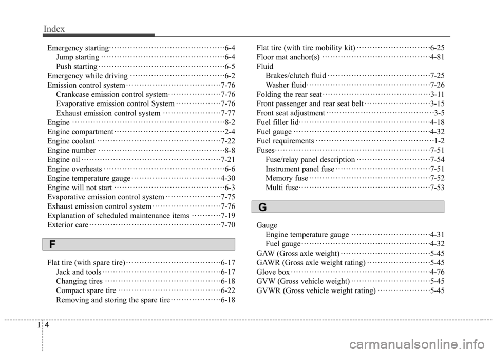
Fuses ··················\
··················\
··················\
···· ·7-51
Fuse/relay panel description ··················\
··········7-54
Instrument panel fuse ··················\
················· ·7-51
Memory fuse ··················\
··················\
········· ·7-52
Multi fuse ··················\
··················\
··············7-53
Gauge Engine temperature gauge ··················\
············4-31
Fuel gauge ··················\
··················\
············ ·4-32
GA
W (Gross axle weight) ··················\
··············· ·5-45
GAWR (Gross axle weight rating) ··················\
······5-45
Glove box ··················\
··················\
·················4-76
GVW (Gross vehicle weight) ··················\
············5-45
GVWR (Gross vehicle weight rating) ··················\
··5-45
F
G