turn signal Hyundai Accent 2019 User Guide
[x] Cancel search | Manufacturer: HYUNDAI, Model Year: 2019, Model line: Accent, Model: Hyundai Accent 2019Pages: 442, PDF Size: 14.14 MB
Page 345 of 442
7-6
Maintenance
Owner Maintenance Schedule
When you stop for fuel:
• Check the engine oil level.
Check the coolant level in theengine coolant reservoir.
Check the windshield washer fluid level.
Check the for low or under-inflated tires.
While operating your vehicle:
Note any changes in the sound ofthe exhaust or any smell of
exhaust fumes in the vehicle.
Check for vibrations in the steering wheel. Notice if there is any
increased steering effort or loose-
ness in the steering wheel, or
change in its straight-ahead posi-
tion.
Notice if your vehicle constantly turns slightly or "pulls" to one side
when traveling on smooth, level
road.
When stopping, listen and check for unusual sounds, pulling to one
side, increased brake pedal travel
or "hard-to-push" brake pedal.
If any slipping or changes in the operation of your transmission
occurs, check the transmission
fluid level.
Check the automatic transmission P (Park) function. Check the parking brake.
Check for fluid leaks under your
vehicle (water dripping from the air
conditioning system during or after
use is normal).
At least monthly:
Check coolant level in the enginecoolant reservoir.
Check the operation of all exterior lights, including the brake lights,
turn signals and hazard warning
flashers.
Check the inflation pressures of all tires including the spare for tires
that are worn, show uneven wear,
or are damaged.
Check for loose wheel lug nuts.
Be careful when checking your
engine coolant level when the
engine is hot. This may result in
coolant being blown out of the
opening and cause serious
burns and other injuries.
WARNING
Page 390 of 442
7-51
7
Maintenance
Fuse NameFuse RatingCircuit Protected
DOOR LOCK20AI/P Junction Block (Tail Gate Unlock Relay, Door Lock/Unlock Relay, Two Turn Unlock Relay)
POWER OUTLET20APower Outlet
SAFETY P/WINDOW25ADriver Safety Power Window Module
STOP LAMP15AI/P Junction Block(Stop Signal Electronic Module)
T/SIGNAL LAMP15ABCM, SLM
C/LIGHTER20ACigarette Lighter
HEATED MIRROR10ADriver Power Outside Mirror, Passenger Power Outside Mirror, A/C Control Module
DRL10ABCM
P/WINDOW RH25APower Window Main Switch, Passenger Power Window Switch
S/HEATER20AFront Seat Warmer Control Module
SPARE110A-
START7.5AWith Smart Key : ECM/PCM, E/R Junction Block(Start Relay), Smart Key Control Module, Transaxle Range Switch, Ignition Lock & Clutch Switch
W/O Smart Key : Burglar Alarm Relay, Transaxle Range Switch, Ignition Lock & Clutch Switch
Page 400 of 442
7-61
7
Maintenance
L
LI
IG
G H
H T
T
B
B U
U L
LB
B S
S
Consult an authorized HYUNDAI
dealer to replace most vehicle light
bulbs. It is difficult to replace vehicle
light bulbs because other parts of the
vehicle must be removed before you
can get to the bulb. This is especially
true for removing the headlamp
assembly to get to the bulb(s).
Removing/installing the headlamp
assembly can result in damage to
the vehicle.
Information
After heavy driving, rain or washing,
headlamp and trunk lenses could
appear frosty. This condition is caused
by the temperature difference
between the lamp inside and the out-
side temperature. This is similar to the
condensation on your windows inside
your vehicle during the rain and does-
n’t indicate a problem with your vehi-
cle. If the water leaks into the lamp
bulb circuitry, have your vehicle
checked by an authorized HYUNDAI
dealer.
Headlamp, Position lamp, Fog
lamp, Daytime Running Light,
Turn Signal Lamp and Side
Marker
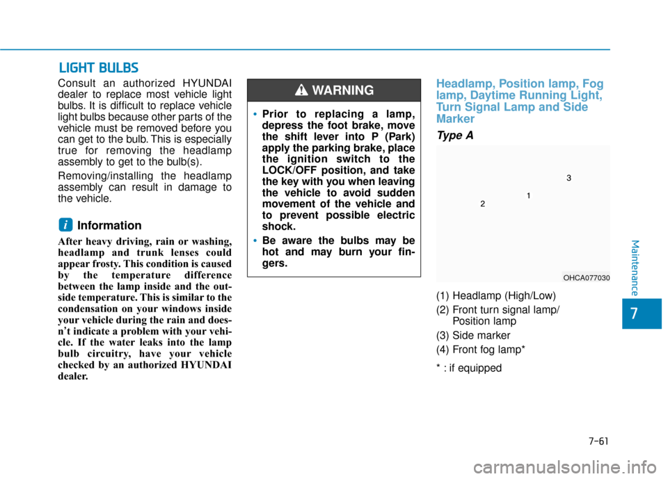
Ty p e A
(1) Headlamp (High/Low)
(2) Front turn signal lamp/
Position lamp
(3) Side marker
(4) Front fog lamp*
* : if equipped
i
Prior to replacing a lamp,
depress the foot brake, move
the shift lever into P (Park)
apply the parking brake, place
the ignition switch to the
LOCK/OFF position, and take
the key with you when leaving
the vehicle to avoid sudden
movement of the vehicle and
to prevent possible electric
shock.
Be aware the bulbs may be
hot and may burn your fin-
gers.
WARNING
OHCA077030
Page 402 of 442
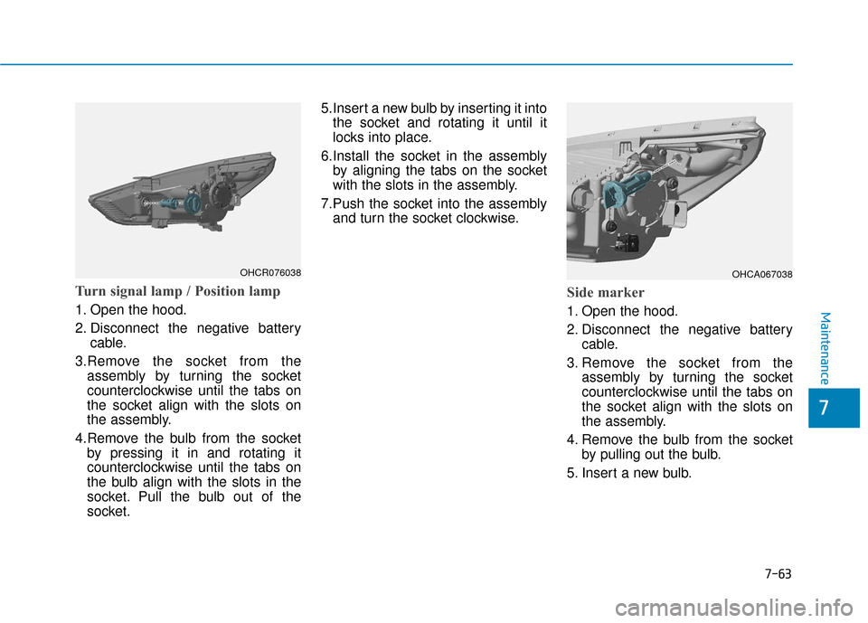
Turn signal lamp / Position lamp
1. Open the hood.
2. Disconnect the negative batterycable.
3.Remove the socket from the assembly by turning the socket
counterclockwise until the tabs on
the socket align with the slots on
the assembly.
4.Remove the bulb from the socket by pressing it in and rotating it
counterclockwise until the tabs on
the bulb align with the slots in the
socket. Pull the bulb out of the
socket. 5.Insert a new bulb by inserting it into
the socket and rotating it until it
locks into place.
6.Install the socket in the assembly by aligning the tabs on the socket
with the slots in the assembly.
7.Push the socket into the assembly and turn the socket clockwise.
Side marker
1. Open the hood.
2. Disconnect the negative battery cable.
3. Remove the socket from the assembly by turning the socket
counterclockwise until the tabs on
the socket align with the slots on
the assembly.
4. Remove the bulb from the socket by pulling out the bulb.
5. Insert a new bulb.
7-63
7
Maintenance
OHCR076038OHCA067038
Page 403 of 442
7-64
Maintenance
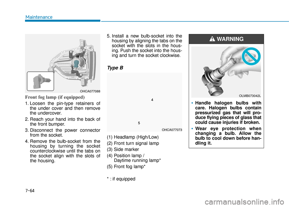
Front fog lamp (if equipped)
1. Loosen the pin-type retainers ofthe under cover and then remove
the undercover.
2. Reach your hand into the back of the front bumper.
3. Disconnect the power connector from the socket.
4. Remove the bulb-socket from the housing by turning the socket
counterclockwise until the tabs on
the socket align with the slots of
the housing. 5. Install a new bulb-socket into the
housing by aligning the tabs on the
socket with the slots in the hous-
ing. Push the socket into the hous-
ing and turn the socket clockwise.
Type B
(1) Headlamp (High/Low)
(2) Front turn signal lamp
(3) Side marker
(4) Position lamp / Daytime running lamp*
(5) Front fog lamp*
* : if equipped
Handle halogen bulbs with
care. Halogen bulbs contain
pressurized gas that will pro-
duce flying pieces of glass that
could cause injuries if broken.
Wear eye protection when
changing a bulb. Allow the
bulb to cool down before han-
dling it.
WARNING
OLMB073042L
OHCA077073
OHCA077088
Page 405 of 442
7-66
Maintenance
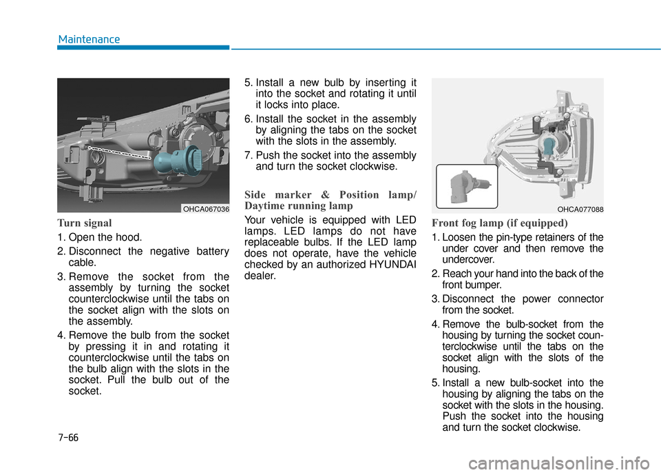
Turn signal
1. Open the hood.
2. Disconnect the negative batterycable.
3. Remove the socket from the assembly by turning the socket
counterclockwise until the tabs on
the socket align with the slots on
the assembly.
4. Remove the bulb from the socket by pressing it in and rotating it
counterclockwise until the tabs on
the bulb align with the slots in the
socket. Pull the bulb out of the
socket. 5. Install a new bulb by inserting it
into the socket and rotating it until
it locks into place.
6. Install the socket in the assembly by aligning the tabs on the socket
with the slots in the assembly.
7. Push the socket into the assembly and turn the socket clockwise.
Side marker & Position lamp/
Daytime running lamp
Your vehicle is equipped with LED
lamps. LED lamps do not have
replaceable bulbs. If the LED lamp
does not operate, have the vehicle
checked by an authorized HYUNDAI
dealer.Front fog lamp (if equipped)
1. Loosen the pin-type retainers of theunder cover and then remove the
undercover.
2. Reach your hand into the back of the front bumper.
3. Disconnect the power connector from the socket.
4. Remove the bulb-socket from the housing by turning the socket coun-
terclockwise until the tabs on the
socket align with the slots of the
housing.
5. Install a new bulb-socket into the housing by aligning the tabs on the
socket with the slots in the housing.
Push the socket into the housing
and turn the socket clockwise.
OHCA077088OHCA067036
Page 406 of 442
7-67
7
Maintenance
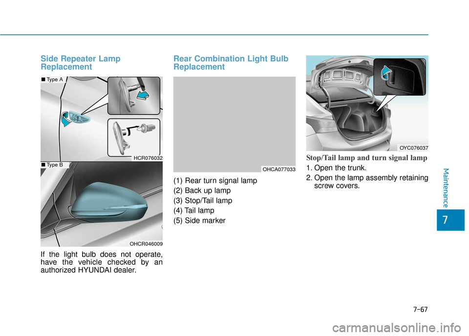
Side Repeater Lamp
Replacement
If the light bulb does not operate,
have the vehicle checked by an
authorized HYUNDAI dealer.
Rear Combination Light Bulb
Replacement
(1) Rear turn signal lamp
(2) Back up lamp
(3) Stop/Tail lamp
(4) Tail lamp
(5) Side marker
Stop/Tail lamp and turn signal lamp
1. Open the trunk.
2. Open the lamp assembly retainingscrew covers.
OYC076037
HCR076032
OHCR046009
■Type A
■Type BOHCA077033
Page 407 of 442
7-68
Maintenance
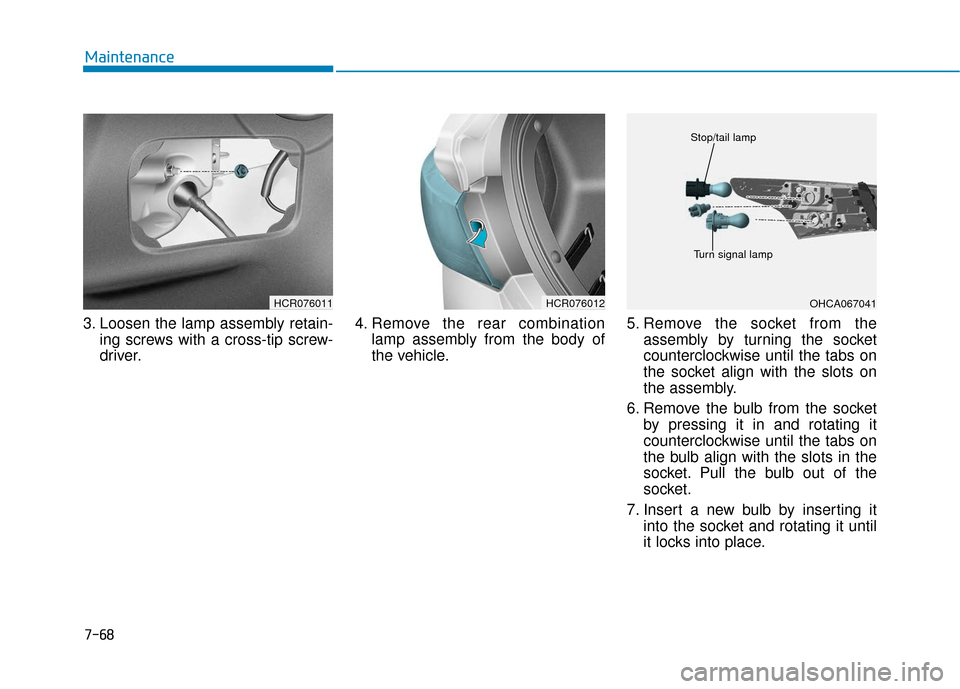
3. Loosen the lamp assembly retain- ing screws with a cross-tip screw-
driver. 4. Remove the rear combination
lamp assembly from the body of
the vehicle. 5. Remove the socket from the
assembly by turning the socket
counterclockwise until the tabs on
the socket align with the slots on
the assembly.
6. Remove the bulb from the socket by pressing it in and rotating it
counterclockwise until the tabs on
the bulb align with the slots in the
socket. Pull the bulb out of the
socket.
7. Insert a new bulb by inserting it into the socket and rotating it until
it locks into place.
HCR076012HCR076011OHCA067041
Stop/tail lamp
Turn signal lamp
Page 425 of 442
B
BU
U L
LB
B
W
W A
AT
TT
TA
A G
G E
E
88
Specifications, Consumer information and Reporting safety defects
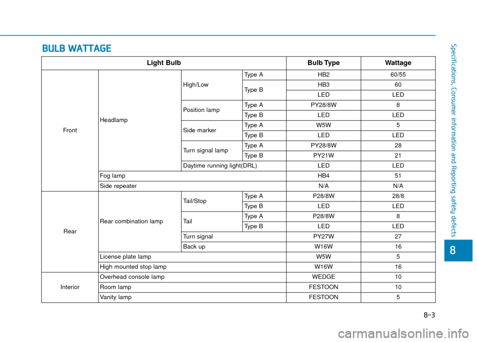
Light Bulb Bulb TypeWattage
FrontHeadlamp High/Low
Type A HB2 60/55
Type B
HB3
60
LED LED
Position lamp Type A
PY28/8W 8
Type B LED LED
Side marker Type A
W5W 5
Type B LED LED
Turn signal lamp Type A
PY28/8W 28
Type B PY21W 21
Daytime running light(DRL) LEDLED
Fog lamp HB451
Side repeater N/AN/A
Rear Rear combination lamp Tail/Stop
Type A
P28/8W 28/8
Type B LED LED
Tail Type A
P28/8W 8
Type B LED LED
Turn signal PY27W27
Back upW16W16
License plate lamp W5W 5
High mounted stop lamp W16W 16
Interior Overhead console lamp WEDGE 10
Room lamp FESTOON 10
Vanity lamp FESTOON 5
8-3
Page 439 of 442
I-5
Instrument Cluster...........................................................3-51Gauges and Meters .....................................................3-53
Instrument Cluster Control .........................................3-52
LCD Display Messages ..............................................3-68
Transmission shift indicator .......................................3-56
Warning and Indicator Lights.....................................3-58
Instrument Panel Overview ..............................................1-5
Interior Features ............................................................3-123 Clock ........................................................................\
3-127
Clothes Hanger .........................................................3-127
Cup Holder ...............................................................3-123
Floor Mat Anchor(s) .................................................3-128
Luggage Net Holder .................................................3-128
Power Outlet.............................................................3-125
Sunvisor ....................................................................3-12\
4
Interior Overview..............................................................1-4
Jump Starting ....................................................................6-4 LCD Display ...................................................................3-72
LCD Display Control .................................................3-72
LCD Display Modes ..................................................3-72
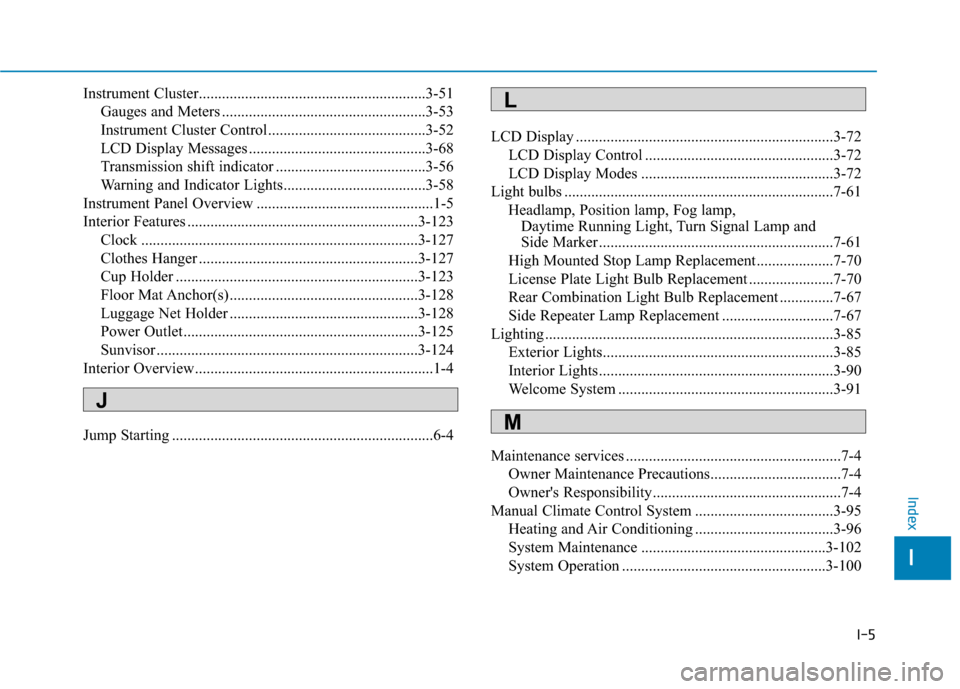
Light bulbs ......................................................................7-\
61 Headlamp, Position lamp, Fog lamp, Daytime Running Light, Turn Signal Lamp and
Side Marker .............................................................7-61
High Mounted Stop Lamp Replacement....................7-70
License Plate Light Bulb Replacement ......................7-70
Rear Combination Light Bulb Replacement ..............7-67
Side Repeater Lamp Replacement .............................7-67
Lighting ........................................................................\
...3-85 Exterior Lights............................................................3-85
Interior Lights.............................................................3-90
Welcome System ........................................................3-91
Maintenance services ........................................................7-4 Owner Maintenance Precautions..................................7-4
Owner's Responsibility.................................................7-4
Manual Climate Control System ....................................3-95 Heating and Air Conditioning ....................................3-96
System Maintenance ................................................3-102
System Operation .....................................................3-100
I
Index
J
L
M