fuel cap Hyundai Atos 2002 User Guide
[x] Cancel search | Manufacturer: HYUNDAI, Model Year: 2002, Model line: Atos, Model: Hyundai Atos 2002Pages: 249, PDF Size: 3.11 MB
Page 157 of 249
FEATURES OF YOUR HYUNDAI
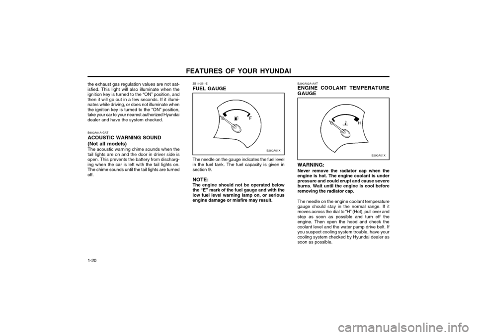
1-20 WARNING: Never remove the radiator cap when the engine is hot. The engine coolant is underpressure and could erupt and cause severeburns. Wait until the engine is cool beforeremoving the radiator cap. The needle on the engine coolant temperature
gauge should stay in the normal range. If itmoves across the dial to “H” (Hot), pull over and stop as soon as possible and turn off the engine. Then open the hood and check thecoolant level and the water pump drive belt. If
you suspect cooling system trouble, have yourcooling system checked by Hyundai dealer assoon as possible.
The needle on the gauge indicates the fuel levelin the fuel tank. The fuel capacity is given insection 9. NOTE: The engine should not be operated below the “E” mark of the fuel gauge and with thelow fuel level warning lamp on, or seriousengine damage or misfire may result. B290A02A-AAT ENGINE COOLANT TEMPERATURE GAUGE
ZB110S1-E FUEL GAUGE
B900A01A-GATACOUSTIC WARNING SOUND (Not all models) The acoustic warning chime sounds when the
tail lights are on and the door in driver side is open. This prevents the battery from discharg-ing when the car is left with the tail lights on.The chime sounds until the tail lights are turnedoff.
the exhaust gas regulation values are not sat-isfied. This light will also illuminate when theignition key is turned to the “ON” position, andthen it will go out in a few seconds. If it illumi-nates while driving, or does not illuminate whenthe ignition key is turned to the “ON” position,take your car to your nearest authorized Hyundaidealer and have the system checked.
B280A01XB290A01X
Page 167 of 249
FEATURES OF YOUR HYUNDAI
1-30
B570A02A
WARNING: Make sure that the support rod has been
released prior to closing the bonnet. Alwaysdouble check to be sure that the bonnet isfirmly latched before driving away. If it is notlatched, the bonnet could fly open while thevehicle is being driven, causing a total lossof visibility, which might result in an acci-dent. The support rod must be insertedcompletely into the hole provided in thebonnet whenever you inspect the enginecompartment. This will prevent the bonnetfrom falling and possibly injuring you. Donot move the vehicle with the bonnet in theraised position, as vision is obstructed andthe bonnet could fall or be damaged.
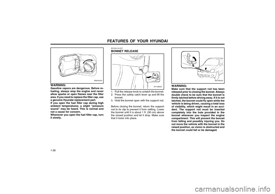
B570A01A-EAT BONNET RELEASE
B560A02A
WARNING: Gasoline vapors are dangerous. Before re-
fueling, always stop the engine and never allow sparks or open flames near the fillerarea. If you need to replace the filler cap, usea genuine Hyundai replacement part.
If you open the fuel filler cap during high
ambient temperatures, a slight “pressuresound” may be heard. This is normal andnot a cause for concern.
Whenever you open the fuel filler cap, turn
it slowly.XV10860E
1. Pull the release knob to unlatch the bonnet.
2. Press the safety catch lever up and lift the bonnet.
3. Hold the bonnet open with the support rod.
Before closing the bonnet, return the support rod to its clip to prevent it from rattling. Lowerthe bonnet until it is about 1 ft. (30 cm) abovethe closed position and let it drop. Make surethat it locks into place.
Page 203 of 249
WHAT TO DO IN AN EMERGENCY
3-2 3. If coolant is running out under the car or
steam is coming out from under the bonnet stop the engine. Do not open the bonnetuntil the coolant has stopped running or thesteaming has stopped. If there is no visibleloss of coolant and no steam, leave theengine running and check to be sure theengine cooling fan is operating. If the fan isnot running, turn the engine off.
4. Check to see if the water pump drive belt is missing. If it is not missing, check to see thatit is tight. If the drive belt seems to besatisfactory, check for coolant leaking fromthe radiator, hoses or under the car. (If theair conditioner had been in use, it is normalfor cold water to be draining from it).
WARNING: While the engine is running, keep hands andclothing away from moving parts such asthe fan and drive belts to prevent injury.
5. If the water pump drive belt is broken or coolant is leaking out, stop the engine imme-diately and call the nearest Hyundai dealerfor assistance.
WARNING: Do not remove the radiator cap when theengine is hot since steam and boiling watermay be ejected from the radiator resulting inburns or scalding.
CAUTION:
Personal injury and damage to the vehicle
may occur if jump starting is not performedcorrectly. If any doubt exists as to how thisoperation should be performed, seek assis-tance from qualified personnel. WARNING:
Motor vehicle batteries contain sulphuric
acid and emit hydrogen gas. Protective cloth- ing should be worn and care exercised toprevent the acid from coming into contactwith skin or clothing and the vehicle. Nakedlights should not be permitted in the vicinityof the battery. Care should be exercised topreventsparks occurring during connection.If acid accidentally comes into contact withskin or eyes, the affected area should imme-diately be flushed with copious amounts ofwater and medical assistance sought.
1. Ensure that the booster battery is 12 volt type. If the booster battery is installed in another vehicle, ensure that the two vehi-cles are not touching.
2. Turn off all unnecessary electrical equip- ment in both vehicles.
3. Ensure that the engine of the vehicle provid- ing the jump start is running prior to connec-tion of the jump cables.
4. Connect the red jump cable to the positive (+) terminal of the booster battery and theother end to the positive (+) terminal of thedischarged battery. 5. Attach the black jump cable to the negative
(-) terminal of the booster battery, and theother end to a ground point within the enginecompartment of the vehicle with the flat bat-tery. Do not connect to the negative batteryterminal of the flat battery since sparks maybe generated with the subsequent risk ofexplosion.
6. Raise the booster vehicle engine speed to 2,000 r.p.m. and start the engine of thevehicle with the flat battery.
7. Remove jump cables in the reverse order of installation (black cable first).
NOTE: If the jump cable is incorrectly installed, damage to the vehicle electrical system mayoccur, in particular the electronic compo-nents such as the Fuel Injection systemcomputer and the Automatic Transaxle com-puter. The battery must never be discon-nected whilst the engine is running. XD040A1-E
IF THE ENGINE OVERHEATS If the temperature gauge indicates overheating:
1. Pull off the road and stop as soon as it is safe to do so.
2. Place the gear selector lever in "P" (auto- matic), or neutral (manual transaxle, semi- automatic transalxe) and set the parkingbrake. If the air conditioner is on, turn it off.
Page 213 of 249
VEHICLE MAINTENANCE REQUIREMENTS
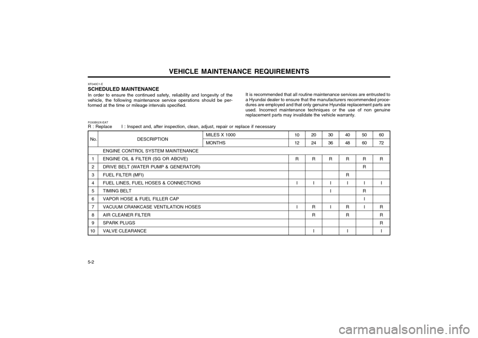
5-2 XF040C1-E SCHEDULED MAINTENANCEIn order to ensure the continued safety, reliability and longevity of the
vehicle, the following maintenance service operations should be per- formed at the time or mileage intervals specified. It is recommended that all routine maintenance services are entrusted to
a Hyundai dealer to ensure that the manufacturers recommended proce-dures are employed and that only genuine Hyundai replacement parts areused. Incorrect maintenance techniques or the use of non genuinereplacement parts may invalidate the vehicle warranty.
F030B02X-EAT R : Replace I : Inspect and, after inspection, clean, adjust, repair or replace if necessary
ENGINE CONTROL SYSTEM MAINTENANCE
1 ENGINE OIL & FILTER (SG OR ABOVE)
2 DRIVE BELT (WATER PUMP & GENERATOR)
3 FUEL FILTER (MFI)
4 FUEL LINES, FUEL HOSES & CONNECTIONS
5 TIMING BELT
6 VAPOR HOSE & FUEL FILLER CAP
7 VACUUM CRANKCASE VENTILATION HOSES
8 AIR CLEANER FILTER
9 SPARK PLUGS
10 VALVE CLEARANCE
No. DESCRIPTION60 72
R
I
R R R I
5060
R R I
R I I
4048
R R I
R R I
1012
R
I I
MILES X 1000 MONTHS30 36
R
II I
20 24
R
I
R R I
Page 216 of 249
VEHICLE MAINTENANCE REQUIREMENTS 5-5
F060A01A-AAT EXPLANATION OF SCHEDULED MAIN-
TENANCE ITEMS
F060M01A-AAT
o Engine oil and filterThe engine oil and filter should be changed at
the intervals specified in the maintenance sched- ule. If the car is being driven in severe condi-tions, more frequent oil and filter changes arerequired.
F060B01A-AAT
o Drive belts Inspect all drive belts for evidence of cuts,
cracks, excessive wear or oil saturation and replace if necessary. Drive belts should be checked periodically for proper tension andadjusted as necessary.
F060C01A-AAT
o Fuel filterA clogged filter can limit the speed at which the
vehicle may be driven, damage the emission system and cause hard starting. If an exces-sive amount of foreign matter accumulates in
the fuel tank, the filter may require replacementmore frequently.
After installing a new filter, run the engine for
several minutes, and check for leaks at theconnections. F060D01A-AAT
o Fuel lines, fuel hoses and connec-
tions
Check the fuel lines, fuel hoses and connec-
tions for leakage and damage. Replace anydamaged or leaking parts immediately.
F060E01A-AAT
o Timing beltInspect all parts related to the timing belt for
damage and deformation. Replace any dam- aged parts immediately.
F060G01A-AAT
o Vapour hose and fuel filler capThe vapor hose and fuel filler cap should be
inspected at those intervals specified in the maintenance schedule. Make sure that a new
vapour hose or fuel filler cap is correctly re-placed.
F060F01A-AAT
o Vacuum, crankcase
ventilation hoses
Inspect the surface of hoses for evidence of
heat and/or mechanical damage. Hard andbrittle rubber, cracking, tears, cuts, abrasions,and excessive swelling indicate deterioration.Particular attention should be paid to examine
those hose surfaces nearest to high heat sourc-
es, such as the exhaust manifold. Inspect the hose routing to assure that the
hoses do not come in contact with any heatsource, sharp edges or moving component
which might cause heat damage or mechanicalwear. Inspect all hose connections, such as
clamps and couplings, to make sure they aresecure, and that no leaks are present. Hoses
should be replaced immediately if there is any
evidence of deterioration or damage.
F060H01A-AAT
o Air cleaner filter A Genuine Hyundai air cleaner filter is recom-
mended when filter is replaced.
F060J01A-AAT
o Spark plugsMake sure to install new spark plugs of the
correct heat range.
F060N01X-GAT
o Valve clearances Incorrect valve clearance will not only result in
unsteady engine operation, but will also cause excessive noise and reduced engine perfor-mance. Inspect valve clearance and adjust asrequired while the engine is hot.
Valve-to-rocker arm clearance Intake valves ..... 0.008 in. (0.2 mm)Exhaust valves .... 0.010 in. (0.25 mm)
Page 219 of 249
DO-IT-YOURSELF MAINTENANCE 6-1
ZG000A1-E
6. DO-IT-YOURSELF MAINTENANCE
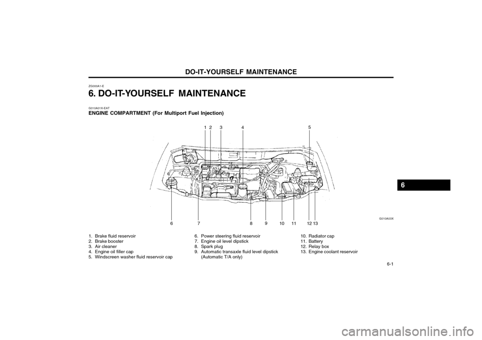
1. Brake fluid reservoir
2. Brake booster
3. Air cleaner
4. Engine oil filler cap
5. Windscreen washer fluid reservoir cap 6. Power steering fluid reservoir
7. Engine oil level dipstick
8. Spark plug
9. Automatic transaxle fluid level dipstick
(Automatic T/A only) 10. Radiator cap
11. Battery
12. Relay box
13. Engine coolant reservoir
G010A01X-EAT
ENGINE COMPARTMENT (For Multiport Fuel Injection)
5
13
129
14
101186 G010A03X
23
7
6
Page 239 of 249
EMISSION CONTROL SYSTEMS 7-1
H010A01A-GAT EMISSION CONTROL SYSTEM (Not all models) Your Hyundai is equipped with an emission
control system to meet all requirements of the Emission prohibition rules of your province.
There are three emission control systems which
are as follows.
1) Crankcase emission control system
2) Evaporative emission control system
3) Exhaust emission control system In order to assure the proper function of the
emission control systems, it is recommended that you have your car inspected and main-tained by an authorized Hyundai dealer in ac-
cordance with the maintenance schedule in thismanual. ZH000A1-A
7. EMISSION
CONTROL SYSTEMS
H010B01A-AAT
1. Crankcase Emission Control Sys-
tem
The Positive Crankcase Ventilation System is
employed to prevent air pollution caused by blow-by gases being emitted from the crank- case. This system supplies fresh filtered air to
the crankcase through the air intake hose.Inside the crankcase, the fresh air mixes with
blow-by gases, which then pass through thePCV valve and into the induction system.
H010D01A-AAT
3. Exhaust Emission Control SystemThe Exhaust Emission Control System is a
highly effective system which controls exhaust
emission while maintaining good vehicle perfor-mance.
H010C02A-GAT
2. Evaporative Emission
Control System (Not all models)
The Evaporative Emission Control System is
designed to prevent fuel vapors from escapinginto the atmosphere.
Canister While the engine is inoperative, fuel vapours
generated inside the fuel tank are absorbed and stored in the onboard canister. When the en-gine is running, the fuel vapors absorbed in thecanister are drawn into the induction systemthrough the purge control solenoid valve.
Purge Control Solenoid Valve The purge control solenoid valve is controlled
by the ECM; when the engine coolant temper- ature is low, and during idling, it closes, so that
evaporated fuel is not taken into the engine.
After engine warm-up, during ordinary driving, itopens so as to introduce evaporated fuel to theengine.
H020A01ACatalytic Converter
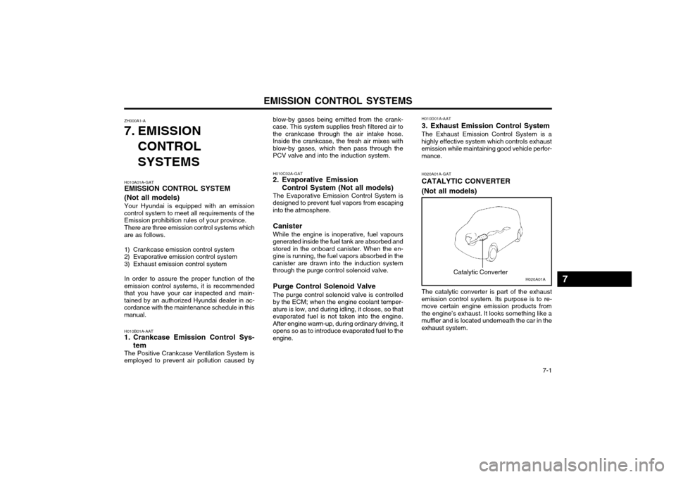
H020A01A-GAT CATALYTIC CONVERTER (Not all models) The catalytic converter is part of the exhaust
emission control system. Its purpose is to re- move certain engine emission products from
the engine’s exhaust. It looks something like amuffler and is located underneath the car in theexhaust system.
7
Page 244 of 249
VEHICLE SPECIFICATIONS 9-1
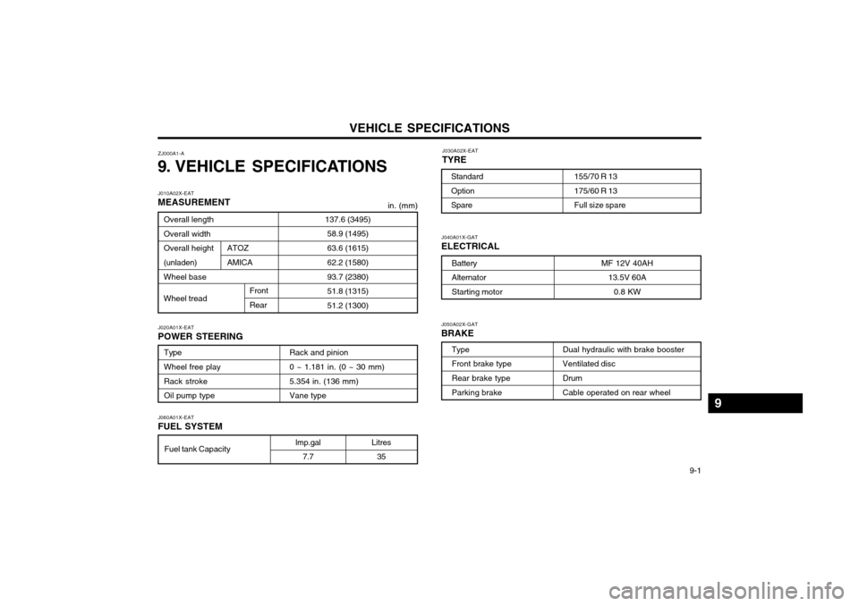
Litres
35 J040A01X-GAT ELECTRICAL
Battery Alternator Starting motor
MF 12V 40AH
13.5V 60A
0.8 KW
J050A02X-GAT BRAKE
Dual hydraulic with brake booster Ventilated disc Drum Cable operated on rear wheel
J060A01X-EAT FUEL SYSTEM
lmp.gal 7.7
J020A01X-EAT POWER STEERING
Type Wheel free play Rack stroke Oil pump type Rack and pinion0 ~ 1.181 in. (0 ~ 30 mm) 5.354 in. (136 mm) Vane type
ZJ000A1-A
9. VEHICLE SPECIFICATIONS J030A02X-EAT TYRE
155/70 R 13 175/60 R 13 Full size spare
Standard Option Spare
J010A02X-EAT MEASUREMENT
137.6 (3495)58.9 (1495) 63.6 (1615) 62.2 (1580) 93.7 (2380) 51.8 (1315) 51.2 (1300)Overall length Overall width Overall height (unladen) Wheel base Wheel tread
in. (mm)
ATOZ AMICA
Front Rear
Fuel tank Capacity Type Front brake type Rear brake type Parking brake
9