fuel cap Hyundai Azera 2009 Owner's Manual
[x] Cancel search | Manufacturer: HYUNDAI, Model Year: 2009, Model line: Azera, Model: Hyundai Azera 2009Pages: 335, PDF Size: 12.4 MB
Page 15 of 335

1FEATURES OF YOUR HYUNDAI2
!
B010A01TG-A
FUEL RECOMMENDATIONS
CAUTION:
Your Hyundai's New Vehicle Limited War-
ranty may not cover damage to the fuel
system and any performance problems
that are caused by the use of fuels con-
taining methanol or fuels containing
MTBE (Methyl Tertiary Butyl Ether) over
15.0% vol. (Oxygen Content 2.7% weight.)
B010B01A-AATWhat About Gasohol?Gasohol (a mixture of 90% unleaded gaso-
line and 10% ethanol or grain alcohol)
may be used in your Hyundai. However, if
your engine develops driveability prob-
lems, the use of 100% unleaded gasoline
is recommended. Fuels with unspecified
quantities of alcohol, or alcohols other
than ethanol, should not be used.
B010A02NF-AATUse Unleaded GasolineUnleaded gasoline with a Pump Octane
Rating of 87 (Research Octane Number
91) or higher must be used in your
Hyundai.
B010C01A-AATUse of MTBEHyundai recommends that fuels contain-
ing MTBE (Methyl Tertiary Butyl Ether)
over 15.0% vol. (Oxygen Content 2.7%
weight) should not be used in your
Hyundai.
Fuel containing MTBE over 15.0% vol.
(Oxygen Content 2.7% weight) may re-
duce vehicle performance and produce
vapor lock or hard starting.
B010D01A-AATDo Not Use MethanolFuels containing methanol (wood alco-
hol) should not be used in your Hyundai.
This type of fuel can reduce vehicle perfor-
mance and damage components of the
fuel system.
!
UNLEADED
FUEL ONLY
WARNING:
o Do not "top off" after the nozzle auto-
matically shuts off when refueling.
o Tighten the cap until it clicks, other-
wise the "
" light will illuminate.
o Always check that the fuel cap is
installed securely to prevent fuel spill-
age in the event of an accident.
Page 86 of 335
1
FEATURES OF YOUR HYUNDAI
73
B260U01TB-AAT
Immobilizer Warning Light
This indicator light comes on for a few
seconds after the ignition key is turned to
the "ON" position. At this time, you can start
the engine. The light goes out after the
engine is running. In case this light goes
out before you start the engine, you must
turn to the "LOCK" position and restart the
engine. In case this light blinks for five
seconds when the ignition key is turned to
the "ON" position, this indicates that the
immobilizer system is out of order. At this
time, refer to the explanation of the "Limp
Home" mode and related procedures (See
page 1-6) or consult your Hyundai dealer.
B270A01O-AATBRAKE PAD WEAR WARNING SOUNDThe front and rear disc brake pads have
wear indicators that should make a high-
pitched squealing or scraping noise when
new pads are needed. The sound may
come and go or be heard all the time when
the vehicle is moving. It may also be heard
when the brake pedal is pushed down
firmly. Excessive rotor damage will result
if the worn pads are not replaced. See your
Hyundai dealer immediately.
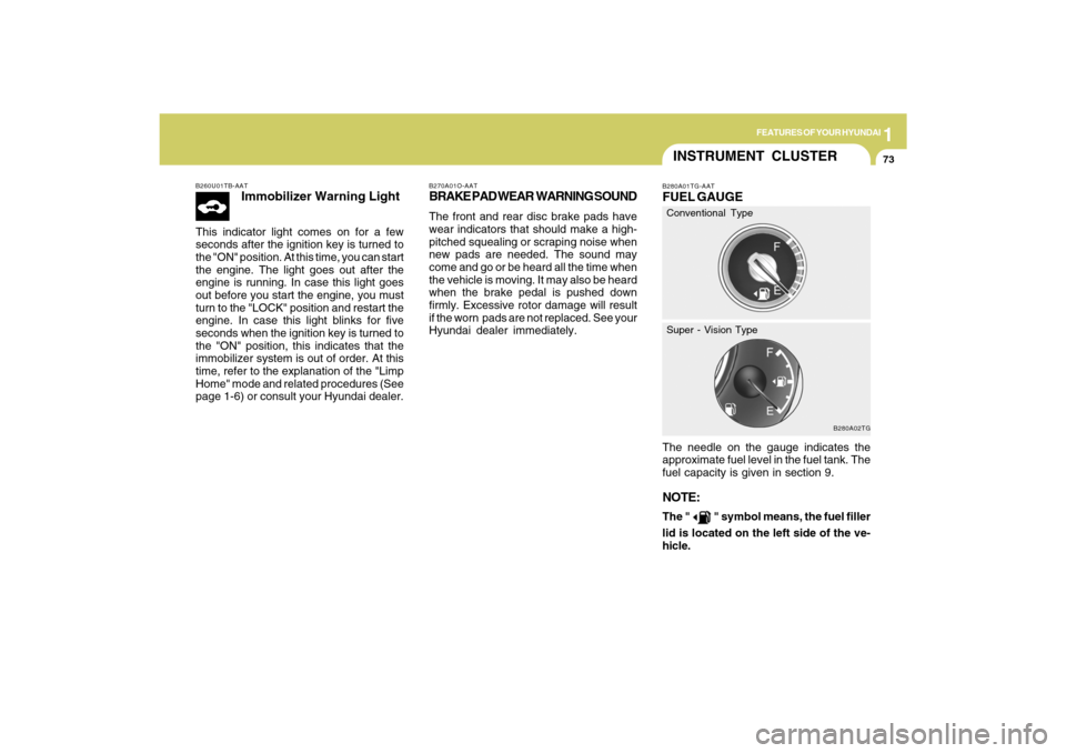
INSTRUMENT CLUSTERB280A01TG-AATFUEL GAUGEThe needle on the gauge indicates the
approximate fuel level in the fuel tank. The
fuel capacity is given in section 9.NOTE:The "
" symbol means, the fuel filler
lid is located on the left side of the ve-
hicle.
B280A02TG
Conventional Type
Super - Vision Type
Page 124 of 335
1
FEATURES OF YOUR HYUNDAI
111
HIGH-MOUNTED REAR
STOP LIGHTB550A02Y-AATIn addition to the lower-mounted rear stop
lights on either side of the car, the high
mounted rear stop light in the center of the
rear window also lights when the brakes
are applied.
B550A01TG-A
!
WARNING:
o Gasoline vapors are dangerous. Be-
fore refueling, always stop the engine
and never smoke or allow sparks and
open flames near the filler area.
o Never operate your vehicle without a
filler cap properly installed, flammable
vapors and gasoline could leak out in
dangerous situations such as a colli-
sion or rollover. If the filler cap must
be replaced, only use genuine Hyundai
replacement parts.
HTG2023
REMOTE FUEL-FILLER LID
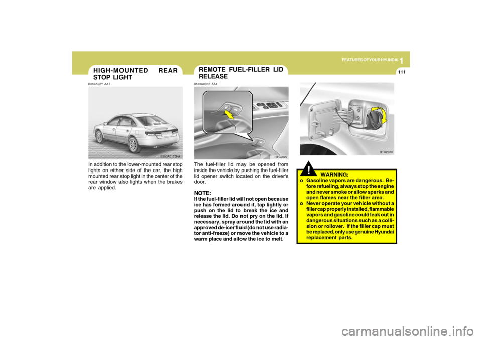
RELEASEB560A03NF-AATThe fuel-filler lid may be opened from
inside the vehicle by pushing the fuel-filler
lid opener switch located on the driver's
door.NOTE:If the fuel-filler lid will not open because
ice has formed around it, tap lightly or
push on the lid to break the ice and
release the lid. Do not pry on the lid. If
necessary, spray around the lid with an
approved de-icer fluid (do not use radia-
tor anti-freeze) or move the vehicle to a
warm place and allow the ice to melt.
HTG2022
Page 125 of 335
1FEATURES OF YOUR HYUNDAI
112
!
WARNING:
!
WARNING:
- Before refueling always note the
location of the Emergency Gaso-
line Shut-Off, if available, at the gas
station facility.
- Before touching the fuel nozzle or
fuel filler cap, you should eliminate
potentially dangerous static elec-
tricity discharge by touching an-
other metal part of the front of the
vehicle, a safe distance away from
the fuel filler neck, nozzle, or other
gas source.
- Do not get back into a vehicle once
you have begun refueling. Do not
touch, rub or slide against any item
or fabric (polyester, satin, nylon,
etc.) capable of producing static
electricity. Static electricity dis-
charge can ignite fuel vapors re-
sulting in explosion.If you must re-enter the vehicle, you
should once again eliminate poten-
tially dangerous static electricity
discharge by touching a metal part
of the vehicle, away from the fuel
filler neck, nozzle or other gasoline
source.
- When using a portable fuel con-
tainer be sure to place the con-
tainer on the ground prior to refuel-
ing. Static electricity discharge from
the container can ignite fuel vapors
causing a fire. Once refueling has
begun, contact with the vehicle
should be maintained until the filling
is complete. Use only portable fuel
containers designed to carry and
store gasoline.
- Do not use cellular phones around
a gas station or while refueling any
vehicle. Electric current and/or elec-
tronic interference from cellular
phones can potentially ignite fuel
vapors causing a fire. If you must
use your cellular phone use it in a
place away from the gas station.
o After refueling, make sure the fuel
cap is installed securely to prevent
fuel spillage in the event of an acci-
dent.
o Tighten the cap until it clicks, other-
wise the "
"light will illuminate.
o If you open the fuel filler cap during
high ambient temperatures, a slight
"pressure sound" may be heard. This
is normal and not a cause for concern.
Whenever you open the fuel filler cap,
turn it slowly.
o Do not "top off" after the nozzle auto-
matically shuts off when refueling.
o Automotive fuels are flammable/ex-
plosive materials. When refueling,
please note the following guidelines
carefully. Failure to follow these guide-
lines may result in severe personal
injury, severe burns or death by fire or
explosion.
!
WARNING:
Page 126 of 335
1
FEATURES OF YOUR HYUNDAI
113
!
WARNING:
- When refueling always shut the en-
gine off. Sparks produced by elec-
trical components related to the
engine can ignite fuel vapors caus-
ing a fire. Always insure that the
engine is OFF before and during
refueling. Once refueling is com-
plete, check to make sure the fuel
filler cap and door are securely
closed, before starting the engine.
- Do not light any fire around a gas
station. DO NOT use matches or a
lighter and DO NOT SMOKE or leave
a lit cigarette in your vehicle while at
a gas station especially during re-
fueling. Automotive fuel is highly
flammable and can, when ignited,
result in explosion by flames.
- If a fire breaks out during refueling,
leave the vicinity of the vehicle, and
immediately contact the manager
of the gas station or contact the
police and local fire department.
Follow any safety instructions they
provide.
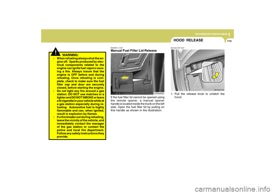
B560B01L-GATManual Fuel Filler Lid ReleaseIf the fuel filler lid cannot be opened using
the remote opener, a manual opener
handle is located inside the trunk on the left
side. Open the fuel filler lid by pulling on
this handle as shown in the illustration.
OTG048702
HOOD RELEASEB570A01NF-GAT1. Pull the release knob to unlatch the
hood.
B570A01TG
Page 230 of 335
2
DRIVING YOUR HYUNDAI
27
!
WARNING:
o Do not load your vehicle any
heavier than the GVWR, either the
maximum front or rear GAWR and
vehicle capacity weight. If you do,
parts, including tires on your ve-
hicle can break, and it can change
the way your vehicle handles and
braking ability. This could cause
you to lose control and crash.
Also, overloading can shorten the
life of your vehicle.
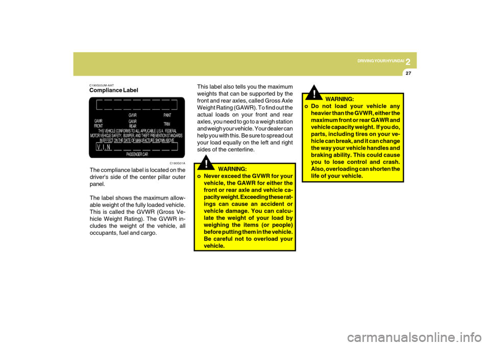
C190G03JM-AATCompliance Label
The compliance label is located on the
driver's side of the center pillar outer
panel.
The label shows the maximum allow-
able weight of the fully loaded vehicle.
This is called the GVWR (Gross Ve-
hicle Weight Rating). The GVWR in-
cludes the weight of the vehicle, all
occupants, fuel and cargo.
C190G01A
!
This label also tells you the maximum
weights that can be supported by the
front and rear axles, called Gross Axle
Weight Rating (GAWR). To find out the
actual loads on your front and rear
axles, you need to go to a weigh station
and weigh your vehicle. Your dealer can
help you with this. Be sure to spread out
your load equally on the left and right
sides of the centerline.
WARNING:
o Never exceed the GVWR for your
vehicle, the GAWR for either the
front or rear axle and vehicle ca-
pacity weight. Exceeding these rat-
ings can cause an accident or
vehicle damage. You can calcu-
late the weight of your load by
weighing the items (or people)
before putting them in the vehicle.
Be careful not to overload your
vehicle.
Page 260 of 335
5
VEHICLE MAINTENANCE REQUIREMENTS4
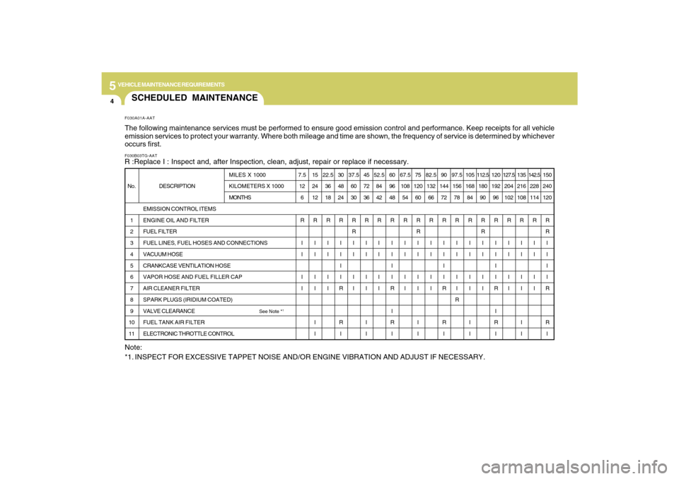
SCHEDULED MAINTENANCEF030B03TG-AATR :Replace I : Inspect and, after Inspection, clean, adjust, repair or replace if necessary.F030A01A-AATThe following maintenance services must be performed to ensure good emission control and performance. Keep receipts for all vehicle
emission services to protect your warranty. Where both mileage and time are shown, the frequency of service is determined by whichever
occurs first.
DESCRIPTION
EMISSION CONTROL ITEMS
ENGINE OIL AND FILTER
FUEL FILTER
FUEL LINES, FUEL HOSES AND CONNECTIONS
VACUUM HOSE
CRANKCASE VENTILATION HOSE
VAPOR HOSE AND FUEL FILLER CAP
AIR CLEANER FILTER
SPARK PLUGS (IRIDIUM COATED)
VALVE CLEARANCE
See Note *
1
FUEL TANK AIR FILTER
ELECTRONIC THROTTLE CONTROL No.
1
2
3
4
5
6
7
8
9
10
11MILES X 1000
KILOMETERS X 1000
MONTHS7.5
12
6
R
I
I
I
I15
24
12
R
I
I
I
I
I
I22.5
36
18
R
I
I
I
I30
48
24
R
I
I
I
I
R
R
I37.5
60
30
R
R
I
I
I
I45
72
36
R
I
I
I
I
I
I52.5
84
42
R
I
I
I
I60
96
48
R
I
I
I
I
R
I
R
I67.5
108
54
R
I
I
I
I75
120
60
R
R
I
I
I
I
I
I82.5
132
66
R
I
I
I
I90
144
72
R
I
I
I
I
R
R
I97.5
156
78
R
I
I
I
I
R105
168
84
R
I
I
I
I
I
I112.5
180
90
R
R
I
I
I
I120
192
96
R
I
I
I
I
R
I
R
I127.5
204
102
R
I
I
I
I135
216
108
R
I
I
I
I
I
I142.5
228
114
R
I
I
I
I150
240
120
R
R
I
I
I
I
R
R
I
Note:
*1. INSPECT FOR EXCESSIVE TAPPET NOISE AND/OR ENGINE VIBRATION AND ADJUST IF NECESSARY.
Page 264 of 335
5
VEHICLE MAINTENANCE REQUIREMENTS8
F070G02A-AATo Brake FluidCheck brake fluid level in the brake fluid
reservoir. The level should be between
"MIN" and "MAX" marks on the side of the
reservoir. Use only hydraulic brake fluid
conforming to DOT 3 or DOT 4.F070F01A-AATo Brake Hoses and LinesVisually check for proper installation, chaf-
ing, cracks, deterioration and any leak-
age. Replace any deteriorated or dam-
aged parts immediately.
F070E06A-AATo Automatic Transaxle FluidThe fluid level should be in the “HOT”
range of the dipstick, after the engine and
transaxle are at normal operating tem-
perature. Check the automatic transaxle
fluid level with the engine running and the
transaxle in neutral, with the parking brake
properly applied. Use HYUNDAI GENU-
INE ATF SP III, DIAMOND ATF SP III, SK
ATF SP III or other brands meeting the SP
III specification approved by Hyundai Motor
Co. when adding or changing fluid. Using
the wrong ATF may result in damage to the
ATM.F070C01A-AATo CoolantThe coolant should be changed at the
intervals specified in the maintenance
schedule.
F060J01A-AATo Spark PlugsMake sure to install new spark plugs of the
correct heat range.F060H01A-AATo Air Cleaner FilterA Genuine Hyundai air cleaner filter is
recommended when the filter is replaced.F060G01A-AATo Vapor Hose and Fuel Filler CapThe vapor hose and fuel filler cap should
be inspected at those intervals specified in
the maintenance schedule. Make sure that
a new vapor hose or fuel filler cap is cor-
rectly replaced.F060N02E-AATo Valve ClearanceInspect excessive valve noise and/or en-
gine vibration and adjust if necessary. A
qualified technician should perform the
operation.
F070H01TG-AATo Rear Disc Brake /
Linings, Parking BrakeCheck the rear disc brake and linings for
scoring, burning, leaking fluid, broken parts,
and excessive wear. Inspect the parking
brake system including the parking brake
pedal and cables. For detailed service
procedures, refer to the Shop Manual.
Page 271 of 335
6
DO-IT-YOURSELF MAINTENANCE
5
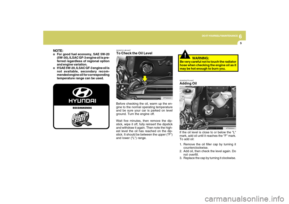
G030C01JM-AATTo Check the Oil LevelBefore checking the oil, warm up the en-
gine to the normal operating temperature
and be sure your car is parked on level
ground. Turn the engine off.
Wait five minutes, then remove the dip-
stick, wipe it off, fully reinsert the dipstick
and withdraw it again. Then note the high-
est level the oil has reached on the dip-
stick. It should be between the upper ("F")
and lower ("L") range.
!
HTG5003-1
NOTE:o For good fuel economy, SAE 5W-20
(5W-30), ILSAC GF-3 engine oil is pre-
ferred regardless of regional option
and engine variation.
o If SAE 5W-20, ILSAC GF-3 engine oil is
not available, secondary recom-
mended engine oil for corresponding
temperature range can be used.
G030D02TG-AATAdding OilIf the oil level is close to or below the "L"
mark, add oil until it reaches the "F" mark.
To add oil:
1. Remove the oil filler cap by turning it
counterclockwise.
2. Add oil, then check the level again. Do
not overfill.
3. Replace the cap by turning it clockwise.
HTG5004-1
WARNING:
Be very careful not to touch the radiator
hose when checking the engine oil as it
may be hot enough to burn you.
Page 305 of 335
7
EMISSION CONTROL SYSTEMS2
EMISSION CONTROL
SYSTEMS
H010B01A-AAT1. Crankcase Emission Control Sys-
temThe positive crankcase ventilation system
is employed to prevent air pollution caused
by blow-by gases being emitted from the
crankcase. This system supplies fresh fil-
tered air to the crankcase through the air
intake hose. Inside the crankcase, the fresh
air mixes with blow-by gases, which then
pass through the PCV valve into the induc-
tion system.
CanisterFuel vapors generated inside the fuel tank
are absorbed and stored in the onboard
canister. When the engine is running, the
fuel vapors absorbed in the canister are
drawn into the surge tank through the
purge control solenoid valve.Purge Control Solenoid Valve (PCSV)The purge control solenoid valve is con-
trolled by the Engine Control Module
(ECM); when the engine coolant tempera-
ture is low during idling, the PCSV closes
so that evaporated fuel is not taken into the
engine. After the engine warms-up during
ordinary driving, the PCSV opens to intro-
duce evaporated fuel to the engine.H010D01A-AAT3. Exhaust Emission Control
SystemThe Exhaust Emission Control System is a
highly effective system which controls ex-
haust emissions while maintaining good
vehicle performance.
H010A01NF-AATYour Hyundai is equipped with an emis-
sion control system to meet all emission
regulations.
There are three emission control systems
which are as follows.
(1) Crankcase emission control system
(2) Evaporative emission control system
(3) Exhaust emission control system
In order to assure the proper function of the
emission control systems, it is recom-
mended that you have your car inspected
and maintained by an authorized Hyundai
dealer in accordance with the maintenance
schedule in this manual.
Caution for the Inspection and Mainte-
nance Test (With Electronic Stability
Control (ESC) system)
o To prevent the vehicle from misfiring
during dynamometer testing, turn the
Electronic Stability Control (ESC) sys-
tem off by pressing the ESC switch.
o After dynamometer testing is com-
pleted, turn the ESC system back on
by pressing the ESC switch again.
H010C01S-AAT2. Evaporative Emission Control (In-
cluding ORVR: Onboard Refuel-
ing Vapor Recovery) SystemThe Evaporative Emission Control Sys-
tem is designed to prevent fuel vapors from
escaping into the atmosphere.
(The ORVR system is designed to allow
the vapors from the fuel tank to be loaded
into a canister while refueling at the gas
station, preventing the escape of fuel va-
pors into the atmosphere.)