horn Hyundai Azera 2010 Owner's Manual
[x] Cancel search | Manufacturer: HYUNDAI, Model Year: 2010, Model line: Azera, Model: Hyundai Azera 2010Pages: 334, PDF Size: 12.24 MB
Page 11 of 334
F11
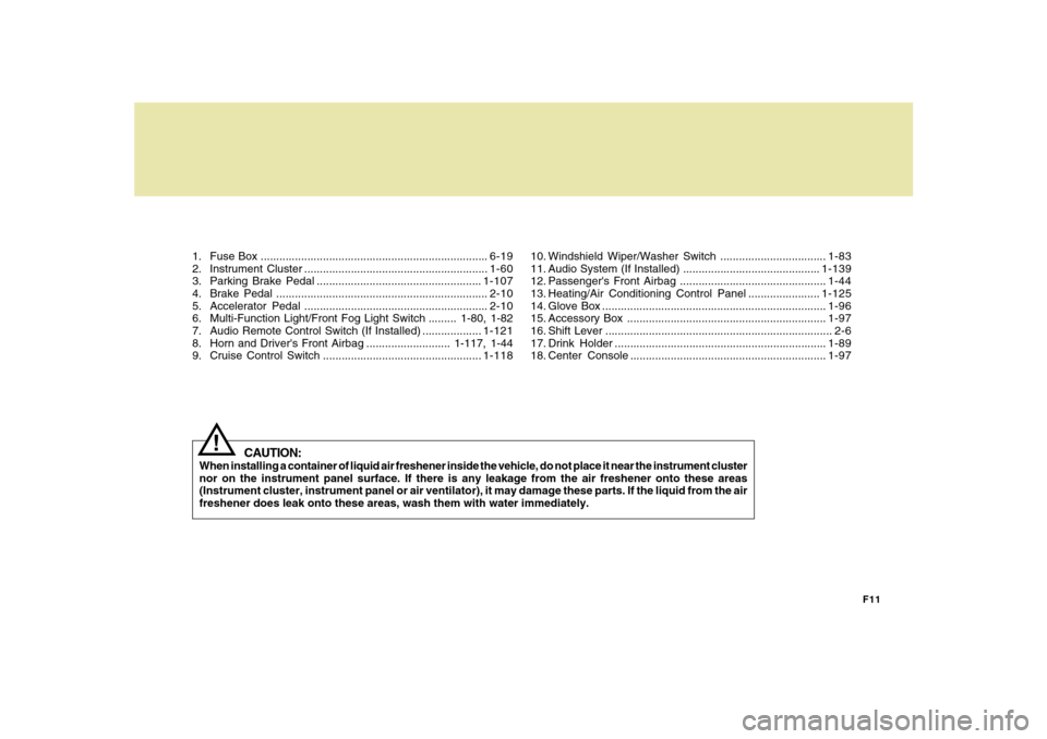
1. Fuse Box .........................................................................6-19
2. Instrument Cluster ...........................................................1-60
3. Parking Brake Pedal .....................................................1-107
4. Brake Pedal ....................................................................2-10
5. Accelerator Pedal ...........................................................2-10
6. Multi-Function Light/Front Fog Light Switch ......... 1-80, 1-82
7. Audio Remote Control Switch (If Installed) ...................1-121
8. Horn and Driver's Front Airbag ........................... 1-117, 1-44
9. Cruise Control Switch ...................................................1-118
CAUTION:
When installing a container of liquid air freshener inside the vehicle, do not place it near the instrument cluster
nor on the instrument panel surface. If there is any leakage from the air freshener onto these areas
(Instrument cluster, instrument panel or air ventilator), it may damage these parts. If the liquid from the air
freshener does leak onto these areas, wash them with water immediately.
!
10. Windshield Wiper/Washer Switch ..................................1-83
11. Audio System (If Installed) ............................................1-139
12. Passenger's Front Airbag ...............................................1-44
13. Heating/Air Conditioning Control Panel .......................1-125
14. Glove Box ........................................................................1-96
15. Accessory Box ................................................................1-97
16. Shift Lever ......................................................................... 2-6
17. Drink Holder ....................................................................1-89
18. Center Console ...............................................................1-97
Page 25 of 334
1FEATURES OF YOUR HYUNDAI12
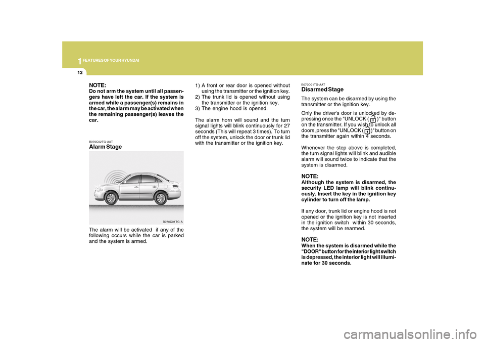
B070C02TG-AATAlarm StageThe alarm will be activated if any of the
following occurs while the car is parked
and the system is armed.
B070C01TG-A
NOTE:Do not arm the system until all passen-
gers have left the car. If the system is
armed while a passenger(s) remains in
the car, the alarm may be activated when
the remaining passenger(s) leaves the
car.
B070D01TG-AATDisarmed StageThe system can be disarmed by using the
transmitter or the ignition key.
Only the driver's door is unlocked by de-
pressing once the "UNLOCK (
)" button
on the transmitter. If you wish to unlock all
doors, press the "UNLOCK ( )" button on
the transmitter again within 4 seconds.
Whenever the step above is completed,
the turn signal lights will blink and audible
alarm will sound twice to indicate that the
system is disarmed.
NOTE:Although the system is disarmed, the
security LED lamp will blink continu-
ously. Insert the key in the ignition key
cylinder to turn off the lamp.
If any door, trunk lid or engine hood is not
opened or the ignition key is not inserted
in the ignition switch within 30 seconds,
the system will be rearmed.NOTE:When the system is disarmed while the
"DOOR" button for the interior light switch
is depressed, the interior light will illumi-
nate for 30 seconds. 1) A front or rear door is opened without
using the transmitter or the ignition key.
2) The trunk lid is opened without using
the transmitter or the ignition key.
3) The engine hood is opened.
The alarm horn will sound and the turn
signal lights will blink continuously for 27
seconds (This will repeat 3 times). To turn
off the system, unlock the door or trunk lid
with the transmitter or the ignition key.
Page 26 of 334
1
FEATURES OF YOUR HYUNDAI
13
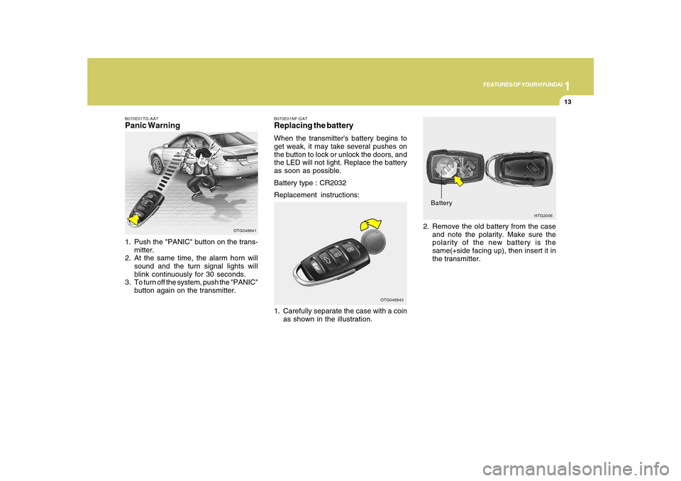
B070E01TG-AATPanic Warning1. Push the "PANIC" button on the trans-
mitter.
2. At the same time, the alarm horn will
sound and the turn signal lights will
blink continuously for 30 seconds.
3. To turn off the system, push the "PANIC"
button again on the transmitter.
OTG048841
HTG2006
Battery2. Remove the old battery from the case
and note the polarity. Make sure the
polarity of the new battery is the
same(+side facing up), then insert it in
the transmitter.
B070E01NF-GATReplacing the batteryWhen the transmitter's battery begins to
get weak, it may take several pushes on
the button to lock or unlock the doors, and
the LED will not light. Replace the battery
as soon as possible.
Battery type : CR2032
Replacement instructions:
1. Carefully separate the case with a coin
as shown in the illustration.
OTG048843
Page 129 of 334
1FEATURES OF YOUR HYUNDAI
116
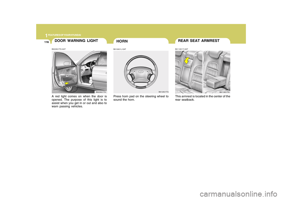
REAR SEAT ARMRESTB611A01Y-AATThis armrest is located in the center of the
rear seatback.
B611A01TG
HORN
DOOR WARNING LIGHTB620A01TG-AATA red light comes on when the door is
opened. The purpose of this light is to
assist when you get in or out and also to
warn passing vehicles.
B620A01TG
B610A01L-GATPress horn pad on the steering wheel to
sound the horn.
B610A01TG
Page 269 of 334
6
DO-IT-YOURSELF MAINTENANCE
3
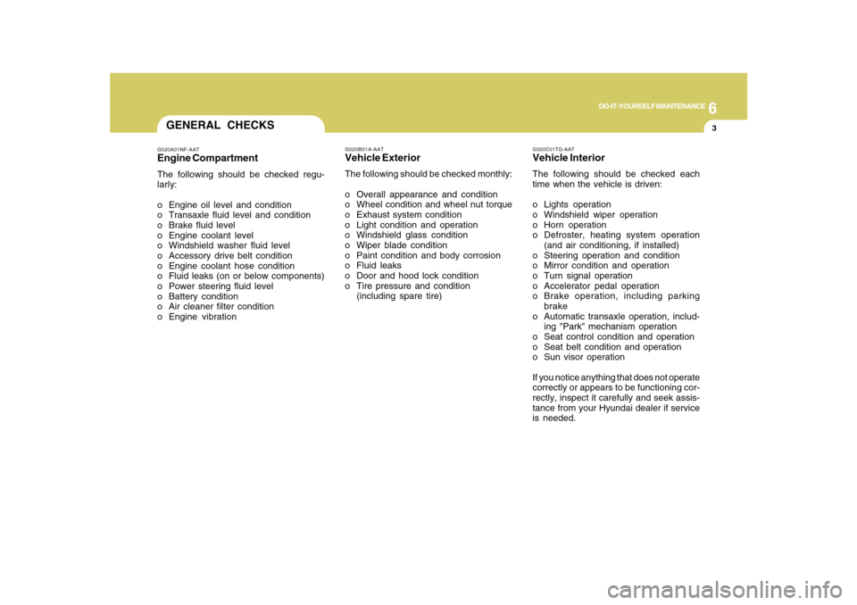
G020C01TG-AATVehicle InteriorThe following should be checked each
time when the vehicle is driven:
o Lights operation
o Windshield wiper operation
o Horn operation
o Defroster, heating system operation
(and air conditioning, if installed)
o Steering operation and condition
o Mirror condition and operation
o Turn signal operation
o Accelerator pedal operation
o Brake operation, including parking
brake
o Automatic transaxle operation, includ-
ing "Park" mechanism operation
o Seat control condition and operation
o Seat belt condition and operation
o Sun visor operation
If you notice anything that does not operate
correctly or appears to be functioning cor-
rectly, inspect it carefully and seek assis-
tance from your Hyundai dealer if service
is needed.
G020B01A-AATVehicle ExteriorThe following should be checked monthly:
o Overall appearance and condition
o Wheel condition and wheel nut torque
o Exhaust system condition
o Light condition and operation
o Windshield glass condition
o Wiper blade condition
o Paint condition and body corrosion
o Fluid leaks
o Door and hood lock condition
o Tire pressure and condition
(including spare tire)
GENERAL CHECKSG020A01NF-AATEngine CompartmentThe following should be checked regu-
larly:
o Engine oil level and condition
o Transaxle fluid level and condition
o Brake fluid level
o Engine coolant level
o Windshield washer fluid level
o Accessory drive belt condition
o Engine coolant hose condition
o Fluid leaks (on or below components)
o Power steering fluid level
o Battery condition
o Air cleaner filter condition
o Engine vibration
Page 300 of 334
6
DO-IT-YOURSELF MAINTENANCE
34
1
2
3
4
5
6
7
8
9
10
11
12
13
14
15
16
17
18
19
20
21
22
23
24
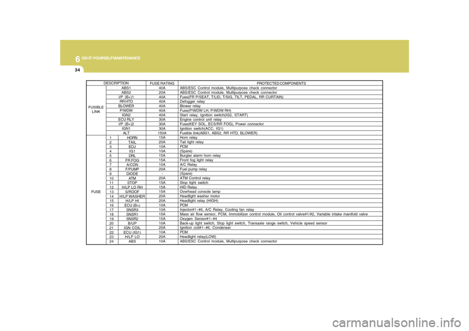
HORN
TAIL
ECU
IG1
DRL
FR FOG
A/CON
F/PUMP
DIODE
ATM
STOP
H/LP LO RH
S/ROOF
H/LP WASHER
H/LP HI
ECU (B+)
SNSR3
SNSR1
SNSR2
B/UP
IGN COIL
ECU (IG1)
H/LP LO
ABSPROTECTED COMPONENTS
ABS/ESC Control module, Multipurpose check connector
ABS/ESC Control module, Multipurpose check connector
Fuse(FR P/SEAT, T/LID, T/SIG, TILT, PEDAL, RR CURTAIN)
Defogger relay
Blower relay
Fuse(P/WDW LH, P/WDW RH)
Start relay, Ignition switch(IG2, START)
Engine control unit relay
Fuse(KEY SOL, ECS/RR FOG), Power connector
Ignition switch(ACC, IG1)
Fusible link(ABS1, ABS2, RR HTD, BLOWER)
Horn relay
Tail light relay
PCM
(Spare)
Burglar alarm horn relay
Front fog light relay
A/C Relay
Fuel pump relay
(Spare)
ATM Control relay
Stop light switch
HID Relay
Overhead console lamp
Headlight washer motor
Headlight relay (HIGH)
PCM
Injector#1~#6, A/C Relay, Cooling fan relay
Mass air flow sensor, PCM, Immobilizer control module, Oil control valve#1/#2, Variable intake manifold valve
Oxygen Sensor#1~#4
Back-up light switch, Stop light switch, Transaxle range switch, Vehicle speed sensor
Ignition coil#1~#6, Condenser
PCM
Headlight relay(LOW)
ABS/ESC Control module, Multipurpose check connector
ABS1
ABS2
I/P (B+)1
RR HTD
BLOWER
P/WDW
IGN2
ECU RLY
I/P (B+)2
IGN1
ALTFUSE RATING
40A
20A
40A
40A
40A
40A
40A
30A
30A
30A
150A
15A
20A
10A
10A
15A
15A
10A
20A
-
20A
15A
15A
15A
20A
20A
10A
10A
15A
15A
10A
20A
10A
20A
10A
DESCRIPTION
FUSIBLE
LINK
FUSE
Page 332 of 334
10
INDEX
4
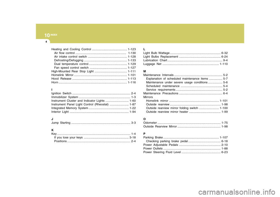
Heating and Cooling Control ..........................................1-123
Air flow control ............................................................. 1-130
Air intake control switch ...............................................1-128
Defrosting/Defogging....................................................1-133
Dual temperature control ..............................................1-129
Fan speed control switch .............................................1-127
High-Mounted Rear Stop Light .......................................1-111
Homelink Mirror ................................................................1-101
Hood Release ..................................................................1-113
Horn..................................................................................1-116
I
Ignition Switch ...................................................................... 2-4
Immobilizer System .............................................................. 1-3
Instrument Cluster and Indicator Lights ............................1-60
Instrument Panel Light Control (Rheostat) .......................1-87
Integrated Memory System ................................................1-22
Interior Light .......................................................................1-94
J
Jump Starting ....................................................................... 3-3
K
Key ........................................................................................ 1-4
If you lose your keys ......................................................3-18
Positions............................................................................ 2-4L
Light Bulb Wattage .............................................................6-32
Light Bulbs Replacement ..................................................6-24
Lubrication Chart .................................................................. 9-4
Luggage Net ....................................................................1-110
M
Maintenance Intervals .......................................................... 5-2
Explanation of scheduled maintenance items ................ 5-7
Maintenance under severe usage conditions ................. 5-6
Scheduled maintenance .................................................. 5-4
Service requirements ........................................................ 5-2
Maintenance Precautions.................................................... 6-4
Mirrors
Homelink mirror ............................................................1-101
Outside rearview .............................................................1-98
Outside rearview mirror folding switch ........................1-100
Outside rearview mirror heater ......................................1-99
O
Odometer............................................................................1-75
Outside Rearview Mirror ....................................................1-98
P
Parking Brake ...................................................................1-107
Checking parking brake pedal .......................................6-18
Power Adjustable Pedals ..................................................2-10
Power Outlets .....................................................................1-88
Power Steering Fluid Level ...............................................6-23