horn Hyundai Coupe 2002 Owner's Manual
[x] Cancel search | Manufacturer: HYUNDAI, Model Year: 2002, Model line: Coupe, Model: Hyundai Coupe 2002Pages: 140, PDF Size: 1.45 MB
Page 30 of 140
CONTROLS AND EQUIPMENT
1- 22 WARNING:
o Extreme Hazard! Do not use a rearward
facing child restraint on a seat protectedby an airbag in front of it!
o Modification to SRS components or wir-ing,
including the addition of any kind of badges to the pad cover or modifications to the body structure, can adversely affect SRS performance and lead to possible injury.
o For cleaning the horn pad, use only a soft, dry cloth or one which has been moist- ened with plain water. Solvents or clean- ers could adversely affect the airbag cover and proper deployment of the system.
o No objects should be placed over or near
the airbag module on the steering wheel, because any such object could cause harm if the vehicle is in a crash severe enough to cause the airbag to inflate.
o If the airbag inflates, it must be replaced by an authorized Hyundai dealer.
o Do not tamper with or disconnect SRS wiring, or other components of the SRS system. Doing so could result in injury, due to accidental firing of the airbag or by rendering the SRS inoperative.
o If components of the airbag system must
be discarded, or if the vehicle must be scrapped, certain safety precautions must be observed. Your Hyundai dealer knows these precautions and can give you the necessary information. Failure to follow these precautions and procedures could increase the risk of personal injury.
WARNING:
o For best protection from the side airbag
system and to avoid being injured by thedeploying side airbag, both front seat oc- cupants should sit in an upright position with the seat belt properly fastened. The driver's hands should be placed on the steering wheel at the 9:00 and 3:00 o'clock positions. The passenger's arms and hands should be placed in their laps.
o Do not use any accessory seat covers.
o Use of seat covers could prevent or re- duce the effectiveness of the system.
o Do not install any accessories on the side or near the side airbag.
o Do not use excessive force on the side of the seat.
o Do not place any objects over the airbag or between the airbag and yourself.
o Do not place any objects (an umbrella, bag, etc.) between the front door and thefront seat. Such objects may become dan- gerous projectiles and cause injury if the supplemental side air bag inflates.
o To prevent unexpected deployment of the
side air bag that may result in personal injury,avoid impact to the side airbag sen- sor when the ignition key is on. FB110C2-F SRS Care
YT10355A
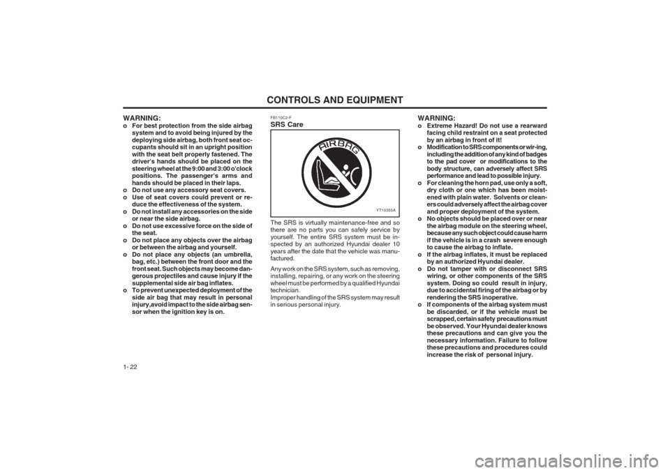
The SRS is virtually maintenance-free and so there are no parts you can safely service by yourself. The entire SRS system must be in- spected by an authorized Hyundai dealer 10 years after the date that the vehicle was manu- factured. Any work on the SRS system, such as removing, installing, repairing, or any work on the steering wheel must be performed by a qualified Hyundai technician. Improper handling of the SRS system may result in serious personal injury.
Page 32 of 140
CONTROLS AND EQUIPMENT
1- 24 8
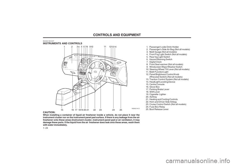
B250A01GK-EAT INSTRUMENTS AND CONTROLS
1. Passenger's side Drink Holder
2. Passenger's Side Air Bag (Not all models)
3. Multi Guage (Not all models)
4. Front Fog Light Switch (Not all models)
5. Rear fog Light Switch
6. Hazard Warning Switch
7. Digital Clock
8. Front Seat warmer (Not all models)
9. Windscreen Wiper/Washer Switch
10. Steering Wheel Tilt Lever (Not all models)
11. Multi-Function Light
12. Panel Brightness Control Knob(Rheostat Switch) (Not all models)
13. Traction Control System (Not all models)
14. HeadLight Leveling Device
15. Centre Console
16. Glove Box
17. Parking Brake Lever
18. Shift Lever
19. Cigarette Lighter
20. Ashtray
21. Heating and Cooling Controls
22. Horn and Driver Side Airbag
23. Cruise Control Switch (Not all models)
24. Fuse Box Relay
25. Boot Release Lever
CAUTION: When installing a container of liquid air freshener inside a vehicle, do not place it near the instrument cluster nor on the instrument panel pad surface. If there is any leakage from the air freshener onto these areas (Instrument cluster, instrument panel pad or air ventilator), it may damage these parts. If the liquid from the air freshener does leak onto these areas, wash them with water immediately. HGK001A-D
12
3
4 5
69 10 11
1213
15
16 17 18 19 20 21 22 23 24
714
25
Page 55 of 140
CONTROLS AND EQUIPMENT1- 47
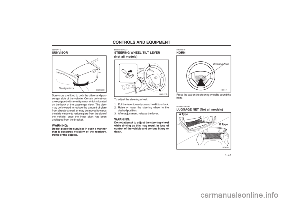
SB530B1-F HORN Press the pad on the steering wheel to sound the horn.
HGK141
Working Zone
B540D01GK-GAT LUGGAGE NET (Not all models)
HGK241
A Type
B Type
SB510A1-E SUNVISOR Sun visors are fitted to both the driver and pas- senger side of the vehicle. Certain derivatives are equipped with a vanity mirror which is located on the back of the passenger visor. The visor may be lowered to reduce the amount of glare from directly ahead, or may be moved towards the side window to reduce glare from the side of the vehicle, once the inner pivot has been unclipped from the bracket. WARNING: Do not place the sunvisor in such a manner that it obscures visibility of the roadway, traffic or the objects.
Vanity mirror
HGK145-D
B600A01HP-AAT STEERING WHEEL TILT LEVER (Not all models) To adjust the steering wheel:
1. Pull the lever toward you and hold it to unlock.
2. Raise or lower the steering wheel to the
desired position.
3. After adjustment, release the lever. WARNING: Do not attempt to adjust the steering wheel while driving as this may result in loss of control of the vehicle and serious injury or death.
HGK127-D
Page 109 of 140
OWNER MAINTENANCE
6-4
SG020B1-E DAILY OPERATING CHECKS The following items should be checked on a daily basis or whenever the vehicle is refuelled, which- ever occurs sooner.
o Engine oil level.
o Engine coolant level.
o Power steering fluid level.
o Brake fluid level.
o Windscreen washer fluid level.
o Battery condition.
o Tyre condition and pressures.
o Operation and cleanliness of all lighting equip-
ment.
o Windscreen wiper and washer operation.
o Horn operation.
o Warning lamp operation.
o Adjustment and cleanliness of mirrors.
o Seat and seat belt adjustment and operation.
o Fluid leakage. The vehicle must not be driven if the daily oper- ating checks indicate that any item of equipment related to the safety or roadworthiness of the vehicle is not functioning correctly. SG030A1-E ENGINE OIL The correct engine oil level is of paramount importance. An excessively high or low oil level may result in irreparable damage being sus- tained by the engine. The engine oil level must be checked on a daily basis or whenever the vehicle is refuelled, whichever occurs sooner. In addition, it is imperative that only an approved grade and specification of oil is used to avoid the possibility of serious engine damage and prema- ture wear. The use of "budget price" oil is a false economy that must be avoided if the maximum reliability and useful life is to be obtained from the vehicle.
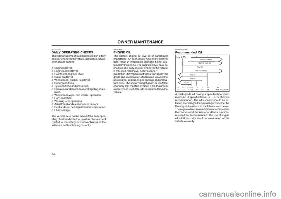
SG030B02GK-E Recommended Oil A multi grade oil having a specification which meets A.P.I. specification of SH, SG or above is recommended. The oil viscosity should be se- lected according to the operating environment of the engine by means of the table shown below. The engine oil recommendations are complete in themselves and the use of additives is neither required nor recommended. The use of engine oil additives may result in invalidation of the vehicle warranty.
SSA6030B°C °F
-25-13 20W-40 20W-50
15W-40 15W-50
10W-30
10W-40 10W-50
5W-40
5W-30
5W-2040
104
20 68
1050
032
-15 5 -10-14
2,7 L V6
Page 127 of 140
OWNER MAINTENANCE
6-22
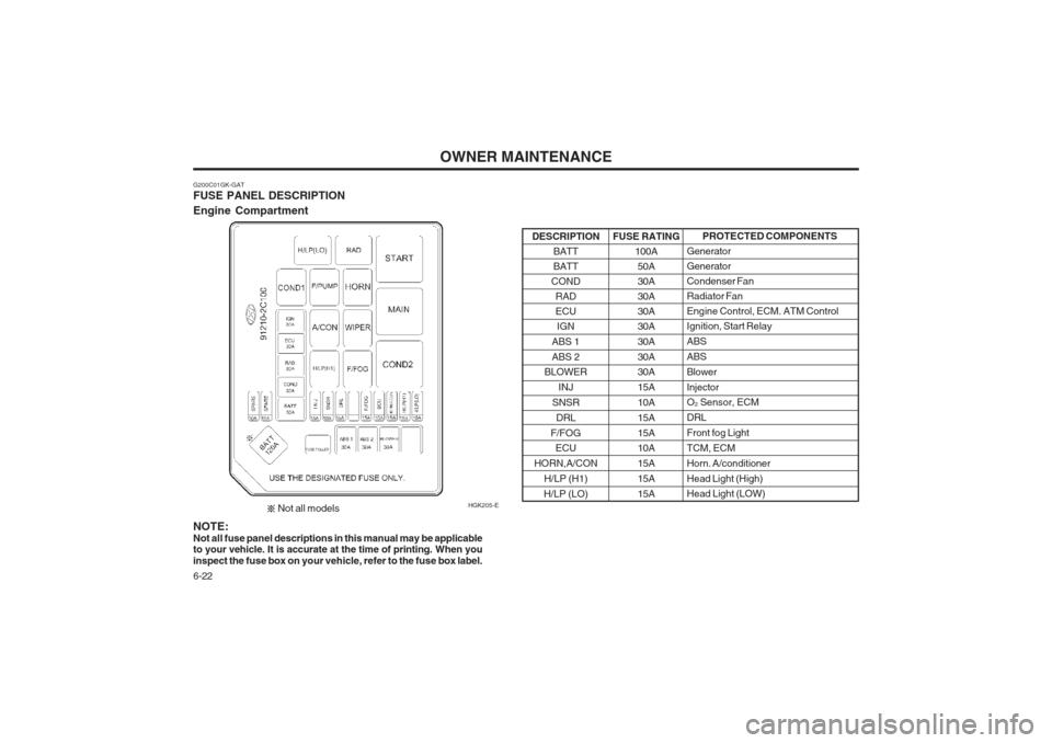
G200C01GK-GAT FUSE PANEL DESCRIPTION Engine Compartment HGK205-EPROTECTED COMPONENTS
GeneratorGeneratorCondenser FanRadiator FanEngine Control, ECM. ATM ControlIgnition, Start Relay ABSABSBlowerInjector O 2 Sensor, ECM
DRL Front fog LightTCM, ECMHorn. A/conditionerHead Light (High) Head Light (LOW)
FUSE RATING
100A50A30A30A30A30A 30A30A 30A 15A10A15A15A 10A 15A15A15A
DESCRIPTION
BATT BATT
COND RADECUIGN
ABS 1 ABS 2
BLOWER
INJ
SNSR DRL
F/FOG ECU
HORN,A/CON H/LP (H1)
H/LP (LO)
NOTE:
Not all fuse panel descriptions in this manual may be applicable
to your vehicle. It is accurate at the time of printing. When youinspect the fuse box on you r vehicle, refer to the fuse box label.
Not all models
Page 138 of 140
INDEX
10-2
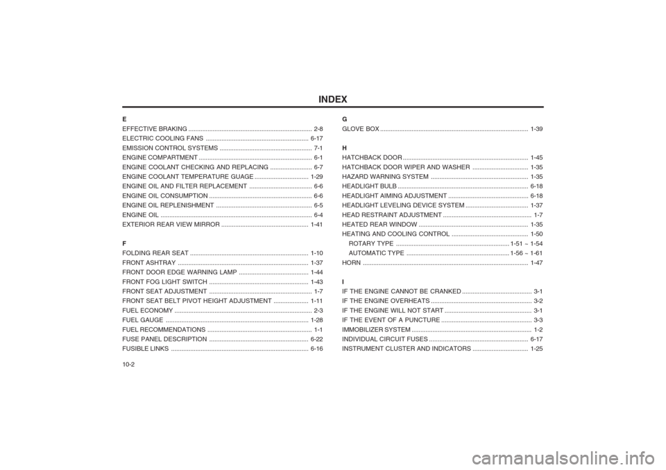
E EFFECTIVE BRAKING
....................................................................... 2-8
ELECTRIC COOLING FANS ........................................................... 6-17
EMISSION CONTROL SYSTEMS ..................................................... 7-1
ENGINE COMPARTMENT ................................................................. 6-1
ENGINE COOLANT CHECKING AND REPLACI NG ........................ 6-7
ENGINE COOLANT TEMPERATURE GUAGE ...............................1-29
ENGINE OIL AND FILTER REPLACEMENT .................................... 6-6
ENGINE OIL CO NSUMPTION ........................................................... 6-6
ENGINE OIL REPLENISHMENT ............ ........................................... 6-5
ENGINE OIL ....................................................................................... 6-4
EXTERIOR REAR VIEW MIRROR .................................................. 1-41
F
FOLDING REAR SEAT .................................................................... 1-10
FRONT ASHTRAY ........ ................................................................... 1-37
FRONT DOOR EDGE WARNING LAMP ........................................1-44
FRONT FOG LIGHT SWITCH ......................................................... 1-43
FRONT SEAT ADJUSTMENT ........................................................... 1-7
FRONT SEAT BELT PIVOT HEIGHT ADJUSTMENT ....................1-11
FUEL ECONOMY ............................................................................... 2-3
FUEL GAUGE .................................................................................. 1-28
FUEL RECOMMENDATIONS ........... ................................................. 1-1
FUSE PANEL DESCRIPTION ......................................................... 6-22
FUSIBLE LINKS ............................................................................... 6-16G
GLOVE BOX .....................................................................................
1-39
H HATCHBACK DOOR ........................................................................ 1-45
HATCHBACK DOOR WIPER AND WA SHER ................................1-35
HAZARD WARNING SYSTEM ........................................................ 1-35
HEADLIGHT BULB ........................................................................... 6-18
HEADLIGHT AIMING ADJUSTMENT ..............................................6-18
HEADLIGHT LEVELING DEVICE SYSTEM ....................................1-37
HEAD RESTRAINT ADJUSTMENT ................................................... 1-7
HEATED REAR WINDOW ............................................................... 1-35
HEATING AND COO LING CONTROL ............................................ 1-50
ROTARY TYPE ................................................................. 1-51 ~ 1-54
AUTOMATIC TYPE ........................................................... 1-56 ~ 1-61
HORN ............................................................................................... 1-47
IIF THE ENGINE CANNOT BE CRANKED ........................................ 3-1
IF THE ENGINE OVERHEATS .......................................................... 3-2
IF THE ENGINE WILL NOT START .................................................. 3-1
IF THE EVENT OF A PUNCTURE .................................................... 3-3
IMMOBILIZER SYSTEM ..................................................................... 1-2
INDIVIDUAL CIRCUIT FUSES ......................................................... 6-17
INSTRUMENT CLUSTER AND INDICATORS ................................1-25