spare wheel Hyundai Coupe 2008 User Guide
[x] Cancel search | Manufacturer: HYUNDAI, Model Year: 2008, Model line: Coupe, Model: Hyundai Coupe 2008Pages: 407, PDF Size: 11.03 MB
Page 325 of 407
3
IN CASE OF EMERGENCY
7
SD070A1-E CHANGING A FLAT TYRE
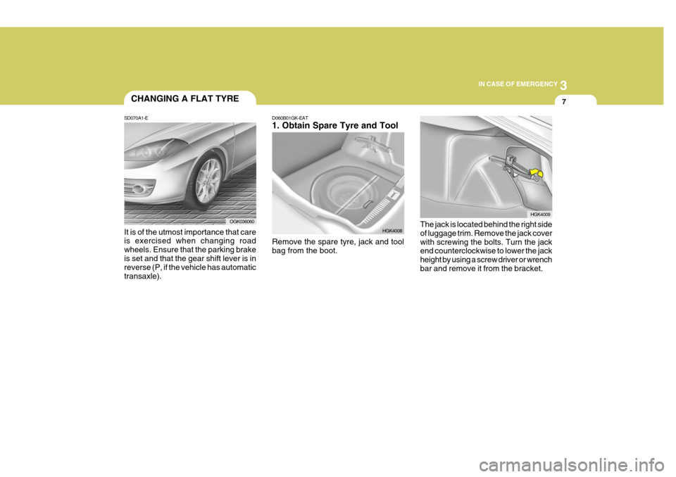
It is of the utmost importance that care is exercised when changing road wheels. Ensure that the parking brakeis set and that the gear shift lever is in reverse (P, if the vehicle has automatic transaxle).
OGK036060
D060B01GK-EAT 1. Obtain Spare Tyre and Tool Remove the spare tyre, jack and tool bag from the boot. HGK4008
HGK4009
The jack is located behind the right side of luggage trim. Remove the jack coverwith screwing the bolts. Turn the jack end counterclockwise to lower the jack height by using a screw driver or wrenchbar and remove it from the bracket.
Page 327 of 407
3
IN CASE OF EMERGENCY
9
D060F01MC
Wheel nut wrench
SD070G1-E 5. Raising the Car
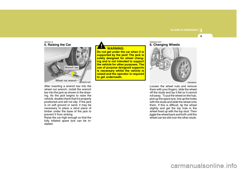
After inserting a wrench bar into the wheel nut wrench, install the wrenchbar into the jack as shown in the draw- ing. As the jack begins to raise the vehicle, double check that it is properlypositioned and will not slip. If the jack is on soft ground or sand, it may be necessary to place a stout piece oftimber under the base of the jack to prevent it from sinking. Raise the car high enough so that thefully inflated spare tyre can be in- stalled.
Wrench bar
!WARNING:
Do not get under the car when it is supported by the jack! The jack is solely designed for wheel chang- ing and is not intended to supportthe vehicle for other purposes. The use of purpose designed supports is necessary whilst the vehicle israised and the operator is required to get underneath.
Loosen the wheel nuts and remove them with your fingers. slide the wheel off the studs and lay it flat so it cannot roll away. To put the wheel on the hub,pick up the spare tyre, line up the holes with the studs and slide the wheel onto them. If this is difficult, tip the wheelslightly and get the top hole in the wheel lined up with the top stud. Then jiggle the wheel back and forth until thewheel can be slid over the other studs.
OGK036403
D060G02Y-EAT 6. Changing Wheels
Page 329 of 407
3
IN CASE OF EMERGENCY
11
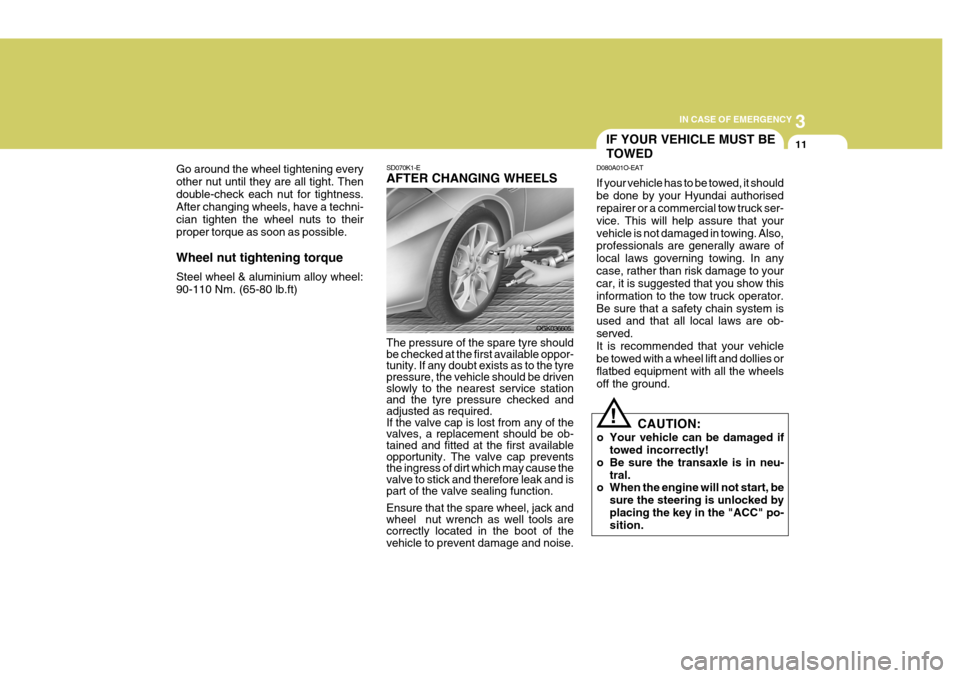
Go around the wheel tightening every other nut until they are all tight. Thendouble-check each nut for tightness. After changing wheels, have a techni- cian tighten the wheel nuts to theirproper torque as soon as possible. Wheel nut tightening torque Steel wheel & aluminium alloy wheel: 90-110 Nm. (65-80 lb.ft)
SD070K1-E AFTER CHANGING WHEELS The pressure of the spare tyre should be checked at the first available oppor-tunity. If any doubt exists as to the tyre pressure, the vehicle should be driven slowly to the nearest service stationand the tyre pressure checked and adjusted as required. If the valve cap is lost from any of thevalves, a replacement should be ob- tained and fitted at the first available opportunity. The valve cap preventsthe ingress of dirt which may cause the valve to stick and therefore leak and is part of the valve sealing function. Ensure that the spare wheel, jack and wheel nut wrench as well tools are correctly located in the boot of the vehicle to prevent damage and noise. OGK036605
IF YOUR VEHICLE MUST BE TOWED
D080A01O-EAT If your vehicle has to be towed, it should be done by your Hyundai authorised repairer or a commercial tow truck ser- vice. This will help assure that yourvehicle is not damaged in towing. Also, professionals are generally aware of local laws governing towing. In anycase, rather than risk damage to your car, it is suggested that you show this information to the tow truck operator.Be sure that a safety chain system is used and that all local laws are ob- served.It is recommended that your vehicle be towed with a wheel lift and dollies or flatbed equipment with all the wheelsoff the ground.
! CAUTION:
o Your vehicle can be damaged if towed incorrectly!
o Be sure the transaxle is in neu- tral.
o When the engine will not start, be
sure the steering is unlocked by placing the key in the "ACC" po- sition.
Page 344 of 407
5VEHICLE MAINTENANCE REQUIREMENTS
6
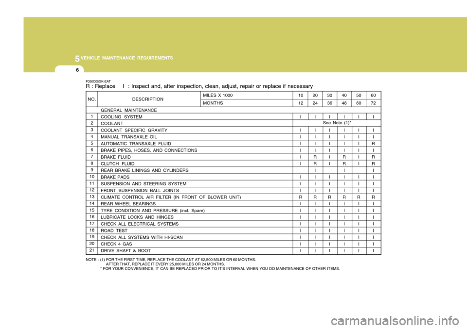
NO.1 2345 6 789
1011 12 1314151617 18 192021 DESCRIPTION
GENERAL MAINTENANCECOOLING SYSTEM COOLANT COOLANT SPECIFIC GRAVITYMANUAL TRANSAXLE OILAUTOMATIC TRANSAXLE FLUIDBRAKE PIPES, HOSES, AND CONNECTIONSBRAKE FLUID CLUTCH FLUID REAR BRAKE LININGS AND CYLINDERSBRAKE PADSSUSPENSION AND STEERING SYSTEMFRONT SUSPENSION BALL JOINTSCLIMATE CONTROL AIR FILTER (IN FRONT OF BLOWER UNIT) REAR WHEEL BEARINGS TYRE CONDITION AND PRESSURE (incl. Spare)LUBRICATE LOCKS AND HINGESCHECK ALL ELECTRICAL SYSTEMSROAD TESTCHECK ALL SYSTEMS WITH HI-SCAN CHECK 4 GAS DRIVE SHAFT & BOOT
F030C05GK-EAT R : Replace I : Inspect and, after inspection, clean, adjust, repair or replace if necessary
60 72
I I I
R
I
RR IIII
R I I IIIII I
50 60
I I IIIII I II
R
I I IIIII I
40 48
I I III
RR IIII
R I I IIIII I
30 36
I I IIIII I II
R I I IIIII I
20 24
I I III
RR IIII
R I I IIIII I
10 12
I I IIIII I II
R
I I IIIII I
MILES X 1000 MONTHS
NOTE : (1) FOR THE FIRST TIME, REPLACE THE COOLANT AT 62,500 MILES OR 60 MONTHS.
AFTER THAT, REPLACE IT EVERY 25,000 MILES OR 24 MONTHS.
* FOR YOUR CONVENIENCE, IT CAN BE REPLACED PRIOR TO IT'S INTERVAL WHEN YOU DO MAINTENANCE OF OTHER ITEMS. See Note (1)*
Page 390 of 407

Vehicle Identification Number (VIN) ............................ 8-2
Engine Number ............................................................ 8-2
Tyre Information ........................................................... 8-3
Tyre Pressures ............................................................. 8-3
Snow Tyres .................................................................. 8-4
Tyre Chains .................................................................. 8-4
Tyre Rotation ............................................................... 8-5
Tyre Balancing ............................................................. 8-6
Tyre Replacement ........................................................ 8-6
Wheel Replacement ..................................................... 8-7
Spare Tyre and Tools .................................................. 8-7
8
CONSUMER INFORMATION
8
Page 394 of 407

8
CONSUMER INFORMATION
5
HGK5016
!
I060A01GK-EAT TYRE ROTATION The tyre wear characteristics will vary between each tyre dependant upon the conditions of use. It is normal for the front tyres to wear more rapidlythan those fitted to the rear of the vehicle and therefore tyre rotation will provide a means of helping to ensurean even wear rate across the tyre set. For vehicles fitted with radial ply tyres, rotation should be confined to front torear tyre alternation. It is not recom- mended that radial ply tyres be ro- tated from side to side. NOTE: Aluminium wheels which are not supplied as Original Equipmentshould not be mixed on the same vehicle with the original steel wheels.
15", 16" Tyre
Sidewall
HGK5018
17" Tyre Tyre rotation direction
WARNING:
When rotating the 215/45 R17 tyres,
ensure to follow the"ROTATION" direction marked on the sidewallof tyres.
When rotating the tyres of the left
and right, separate the wheel fromthe tyre and then re-assemble them. However, it is acceptable that the steel spare wheel be used in con-junction with Original Equipment aluminium wheels since the offset of both wheels is compatible. Ra-dial and cross ply tyres should not be mixed on the same vehicle.
Page 396 of 407

8
CONSUMER INFORMATION
7
!
I100A01FC-EAT SPARE TYRE AND TOOLS
Your Hyundai is delivered with the following: Spare tyre and wheel Wheel nut wrench, Wrench bar,ScrewdriverJack HGK4008
SI060D1-E
WHEEL REPLACEMENT
The original wheels may only be re-
placed with Hyundai Approved Wheels.
WARNING:
Driving on worn or defective tyres
is dangerous. Worn tyres may cause loss of steering control anda serious deterioration of braking efficiency. Defective tyres may cause vibration and loss of con-trol through blow outs.
Tyres of different size, construction or
tread pattern should not be intermixedon the same axle. Radial and cross ply tyres should not be used on the same vehicle. The use of tyres and wheels of non
approved sizes can be dangerous.
Page 398 of 407

9 VEHICLE SPECIFICATIONS
2
Type Wheel free play Rack stroke Oil pump type Rack and pinion0 ~ 1.18 in. (0 ~ 30 mm)5.20 in. (132 mm) Vane type
Option
Fuel tank capacity
195/65 R15, 205/55 R16, 215/45 R17
Dual hydraulic with brake booster Ventilated disc Solid discCable
Type Front brake type Rear brake typeParking brake
55 litres
SJ030A1-E FUEL SYSTEM
J020A01GK-EAT POWER STEERING J030A01GK-EATTYRE
J050A01GK-GAT BRAKE
J035A02GK-EAT SPARE TYRE
Standard
T125/70 R16 (Temporary)
173 (4395)
69.3 (1760) 52.4 (1330)99.6 (2530) 58.7 (1490) 59.5 (1510)59.1 (1500)
J010A02GK-EAT MEASUREMENTOverall length Overall widthOverall height (unladen) Wheel base Wheel tread
195/65 R15 205/55 R16215/45 R17
in. (mm)
Front RearFront Rear FrontRear
Page 405 of 407

10
INDEX
5
Transaxle Automatic ................................................................. 2-9
Automatic transaxle fluid checking .......................... 6-15
Manual ...................................................................... 2-7
Trip Computer ............................................................. 1-49
Trip Odometer ............................................................. 1-48
Tyres ........................................................................... 8-3
Balancing .................................................................. 8-6
Chains ...................................................................... 8-4
Changing a flat tyre .................................................. 3-7
Information ................................................................ 8-3
Pressure ................................................................... 8-3
Replacement ............................................................. 8-6
Rotation .................................................................... 8-5
Snow tyres ............................................................... 8-4
Spare tyre ................................................................. 3-5 Wheel replacement ................................................... 8-7
VVehicle Identification Number (VIN) ............................. 8-2
Vehicle Specifi cation ................................................... 9-2
Ventilator
Centre ventilator ...................................................... 1-82
Side ventilator .......................................................... 1-82
WWasher Reservoir ....................................................... 6-13
Warning and Indicator Lights ...................................... 1-42
Windows Glass ........................................................... 1-11
Windscreen Wiper and Washer ...................................1-55
Windscreen Wiper Blades ........ ...................................6-12