sensor Hyundai Elantra 2007 User Guide
[x] Cancel search | Manufacturer: HYUNDAI, Model Year: 2007, Model line: Elantra, Model: Hyundai Elantra 2007Pages: 339, PDF Size: 11.19 MB
Page 65 of 339
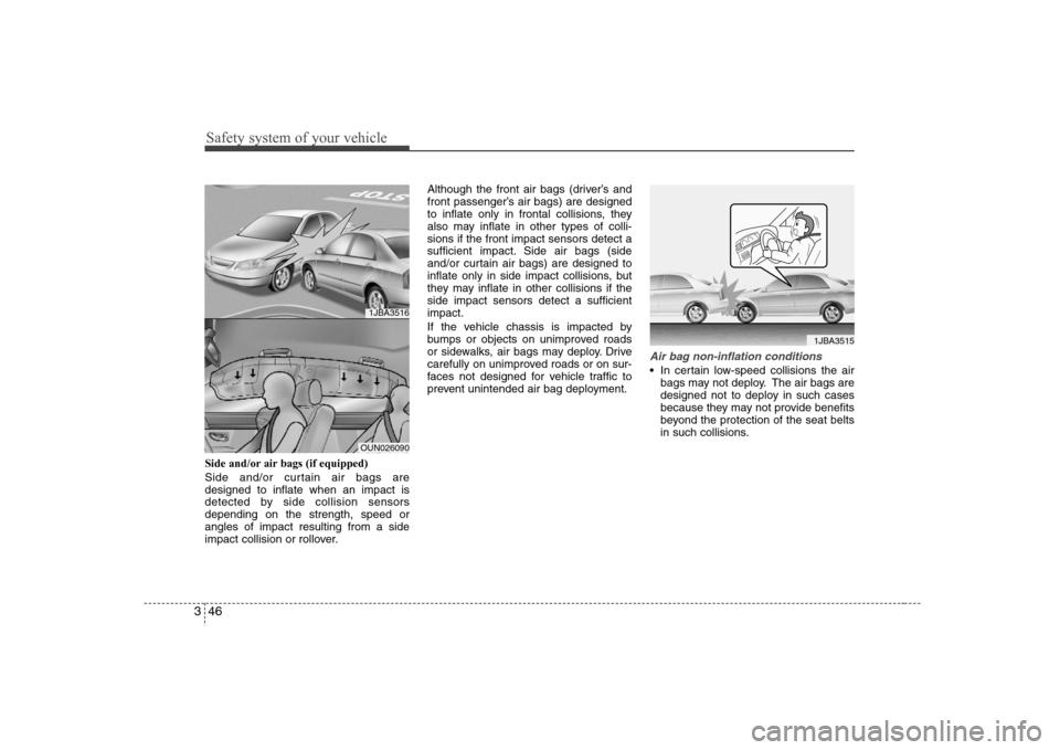
Safety system of your vehicle46 3Side and/or air bags (if equipped)
Side and/or curtain air bags are
designed to inflate when an impact is
detected by side collision sensors
depending on the strength, speed or
angles of impact resulting from a side
impact collision or rollover.Although the front air bags (driver’s and
front passenger’s air bags) are designed
to inflate only in frontal collisions, they
also may inflate in other types of colli-
sions if the front impact sensors detect a
sufficient impact. Side air bags (side
and/or curtain air bags) are designed to
inflate only in side impact collisions, but
they may inflate in other collisions if the
side impact sensors detect a sufficient
impact.
If the vehicle chassis is impacted by
bumps or objects on unimproved roads
or sidewalks, air bags may deploy. Drive
carefully on unimproved roads or on sur-
faces not designed for vehicle traffic to
prevent unintended air bag deployment.
Air bag non-inflation conditions In certain low-speed collisions the air
bags may not deploy. The air bags are
designed not to deploy in such cases
because they may not provide benefits
beyond the protection of the seat belts
in such collisions.
1JBA3515
1JBA3516OUN026090
Page 66 of 339
347
Safety system of your vehicle
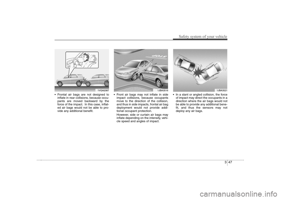
Frontal air bags are not designed to
inflate in rear collisions, because occu-
pants are moved backward by the
force of the impact. In this case, inflat-
ed air bags would not be able to pro-
vide any additional benefit. Front air bags may not inflate in side
impact collisions, because occupants
move to the direction of the collision,
and thus in side impacts, frontal air bag
deployment would not provide addi-
tional occupant protection.
However, side or curtain air bags may
inflate depending on the intensity, vehi-
cle speed and angles of impact. In a slant or angled collision, the force
of impact may direct the occupants in a
direction where the air bags would not
be able to provide any additional bene-
fit, and thus the sensors may not
deploy any air bags.
1VQA2087
1JBA3521
1JBA3516
Page 67 of 339
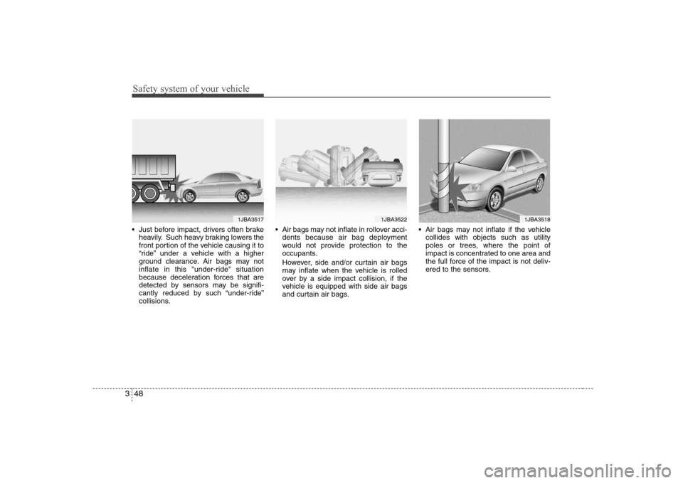
Safety system of your vehicle48 3 Just before impact, drivers often brake
heavily. Such heavy braking lowers the
front portion of the vehicle causing it to
“ride” under a vehicle with a higher
ground clearance. Air bags may not
inflate in this "under-ride" situation
because deceleration forces that are
detected by sensors may be signifi-
cantly reduced by such “under-ride”
collisions. Air bags may not inflate in rollover acci-
dents because air bag deployment
would not provide protection to the
occupants.
However, side and/or curtain air bags
may inflate when the vehicle is rolled
over by a side impact collision, if the
vehicle is equipped with side air bags
and curtain air bags. Air bags may not inflate if the vehicle
collides with objects such as utility
poles or trees, where the point of
impact is concentrated to one area and
the full force of the impact is not deliv-
ered to the sensors.
1JBA3517
1JBA3522
1JBA3518
Page 68 of 339
349
Safety system of your vehicle
How does the air bag system
operate Air bag only operates when the ignition
switch is turned to ON or START posi-
tion.
Air bags inflate instantly in the event of
serious frontal or side collision (if
equipped with side air bag or curtain
air bag) in order to help protect the
occupants from serious physical injury.
There is no single speed at which the
air bags will inflate.
Generally, air bags are designed to
inflate by the severity of a collision and
its direction. These two factors deter-
mine whether the sensors send out an
electronic deployment/inflation signal.
Air bag deployment depends on a
number of factors including vehicle
speed, angles of impact and the densi-
ty and stiffness of the vehicles or
objects which your vehicle hits in the
collision. Though, factors are not limit-
ed to those mentioned above.
The front air bags will completely
inflate and deflate in an instant.
It is virtually impossible for you to see
the air bags inflate during an accident.
It is much more likely that you will sim-
ply see the deflated air bags hanging
out of their storage compartments after
the collision. In order to help provide protection in a
severe collision, the air bags must
inflate rapidly. The speed of air bag
inflation is a consequence of the
extremely short time in which a collision
occurs and the need to get the air bag
between the occupant and the vehicle
structures before the occupant impacts
those structures. This speed of inflation
reduces the risk of serious or life-
threatening injuries in a severe collision
and is thus a necessary part of air bag
design.
However, air bag inflation can also
cause injuries which normally can
include facial abrasions, bruises and
broken bones, and sometimes more
severe injuries because the inflation
speed also causes the air bags to
expand with a great deal of force.
There are even circumstances
under which contact with the steer-
ing wheel air bag can cause fatal
injuries, especially if the occupant
is positioned excessively close to
the steering wheel.
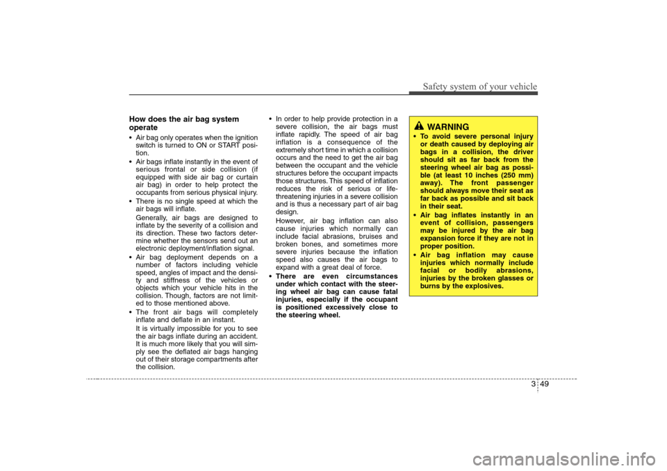
WARNING
To avoid severe personal injury
or death caused by deploying air
bags in a collision, the driver
should sit as far back from the
steering wheel air bag as possi-
ble (at least 10 inches (250 mm)
away). The front passenger
should always move their seat as
far back as possible and sit back
in their seat.
Air bag inflates instantly in an
event of collision, passengers
may be injured by the air bag
expansion force if they are not in
proper position.
Air bag inflation may cause
injuries which normally include
facial or bodily abrasions,
injuries by the broken glasses or
burns by the explosives.
Page 84 of 339
411
Features of your vehicle
Impact sensing door unlock sys-
tem (if equipped)All doors will be automatically unlocked
when the impact is delivered to impact
sensors while the ignition switch ON.
However, the doors may not be unlocked
when there are some problems of
mechanical door lock system or battery.Speed sensing door lock system
(if equipped)When the speed of the vehicle keeps
above 20 km/h for 1 second, it will auto-
matically lock all doors. For activation of
this feature, contact an authorized
Hyundai dealer.
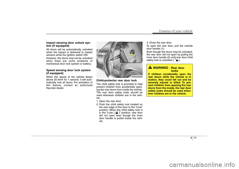
Child-protector rear door lockThe child safety lock is provided to help
prevent children from accidentally open-
ing the rear doors from inside the vehicle.
The rear door safety locks should be
used whenever children are in the vehi-
cle.
1. Open the rear door.
2. Push the child safety lock located on
the rear edge of the door to the “Lock”
position. When the child safety lock is
in the “Lock ( )” position, rear door
will not open even though the inner
door handle is pulled inside the vehi-
cle.3. Close the rear door.
To open the rear door, pull the outside
door handle (1).
Even though the doors may be unlocked,
the rear door will not open by pulling the
inner door handle (2) until rear door child
safety lock is unlocked ( ).
WARNING
- Rear door
locks
If children accidentally open the
rear doors while the vehicle is in
motion, they could fall out and be
severely injured or killed. To pre-
vent children from opening the rear
doors from the inside, the rear door
safety locks should be used when-
ever children are in the vehicle.
OHD046005
Page 103 of 339
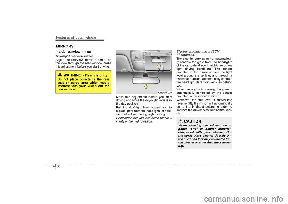
Features of your vehicle30 4Inside rearview mirrorDay/night rearview mirror Adjust the rearview mirror to center on
the view through the rear window. Make
this adjustment before you start driving.
Make this adjustment before you start
driving and while the day/night lever is in
the day position.
Pull the day/night lever toward you to
reduce glare from the headlights of vehi-
cles behind you during night driving.
Remember that you lose some rearview
clarity in the night position.Electric chromic mirror (ECM)
(if equipped)
The electric rearview mirror automatical-
ly controls the glare from the headlights
of the car behind you in nighttime or low
light driving conditions. The sensor
mounted in the mirror senses the light
level around the vehicle, and through a
chemical reaction, automatically controls
the headlight glare from vehicles behind
you.
When the engine is running, the glare is
automatically controlled by the sensor
mounted in the rearview mirror.
Whenever the shift lever is shifted into
reverse (R), the mirror will automatically
go to the brightest setting in order to
improve the drivers view behind the vehi-
cle.
MIRRORS
WARNING -
Rear visibility
Do not place objects in the rear
seat or cargo area which would
interfere with your vision out the
rear window.
OHD046023
CAUTION
When cleaning the mirror, use a
paper towel or similar material
dampened with glass cleaner. Do
not spray glass cleaner directly on
the mirror as that may cause the liq-
uid cleaner to enter the mirror hous-
ing.
Page 104 of 339
431
Features of your vehicle
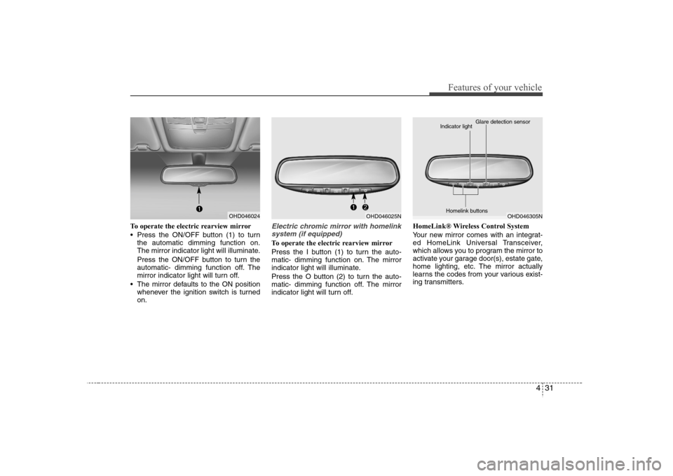
To operate the electric rearview mirror
Press the ON/OFF button (1) to turn
the automatic dimming function on.
The mirror indicator light will illuminate.
Press the ON/OFF button to turn the
automatic- dimming function off. The
mirror indicator light will turn off.
The mirror defaults to the ON position
whenever the ignition switch is turned
on.
Electric chromic mirror with homelink
system (if equipped)To operate the electric rearview mirror
Press the I button (1) to turn the auto-
matic- dimming function on. The mirror
indicator light will illuminate.
Press the O button (2) to turn the auto-
matic- dimming function off. The mirror
indicator light will turn off.HomeLink® Wireless Control System
Your new mirror comes with an integrat-
ed HomeLink Universal Transceiver,
which allows you to program the mirror to
activate your garage door(s), estate gate,
home lighting, etc. The mirror actually
learns the codes from your various exist-
ing transmitters.
OHD046024
OHD046025N
OHD046305N Glare detection sensor
Indicator light
Homelink buttons
Page 279 of 339
Maintenance24 7Replace the filter according to the
Scheduled Maintenance Section.If the vehicle is operated in extremely
dusty or sandy areas, replace the ele-
ment more often than the usual recom-
mended intervals. (Refer to
“Maintenance under severe usage condi-
tions” in this section.)
CAUTION
Do not drive with the air cleaner
removed; this will result in exces-
sive engine wear.
When removing the air cleaner fil-
ter, be careful that dust or dirt
does not enter the air intake, or
damage may result.
Use a Hyundai genuine part. Use
of nongenuine part could damage
the air flow sensor.
Page 305 of 339
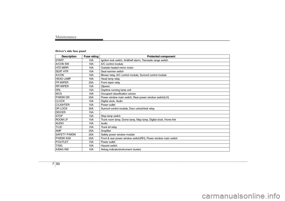
Maintenance50 7Driver's side fuse panel
Description Fuse rating Protected component
START 10A Ignition lock switch, Antitheft alarm, Transaxle range switch
A/CON SW 10A A/C control module
HTD MIRR 10A Outside heated mirror motor
SEAT HTR 15A Seat warmer switch
A/CON 10A Blower relay, A/C control module, Sunroof control module
HEAD LAMP 10A Head lamp relay
FR WIPER 25A Front wiper relay
RR WIPER 15A (Spare)
DRL 15A Daytime running lamp unit
WCS 10A Occupant classification sensor
P/WDW DR 25A Power window main switch, Rear power window switch(LH)
CLOCK 10A Digital clock, Audio
C/LIGHTER 15A Power outlet
DR LOCK 20A Sunroof control module, Door unlock/lock relay
DEICER 15A -
STOP 15A Stop lamp switch
ROOM LP 15A Trunk room lamp, Dome lamp, Map lamp, Digital clock, Home link
AUDIO 15A Audio
T/LID 15A Trunk lid relay
AMP 25A Amplifier
SAFETY P/WDW 25A Safety power window module
P/WDW ASS 25A Front & rear power window switch(RH), Power window main switch
P/OUTLET 15A Power outlet
T/SIG 10A Hazard switch
A/BAG IND 10A Airbag indicator(instrument cluster)
Page 307 of 339
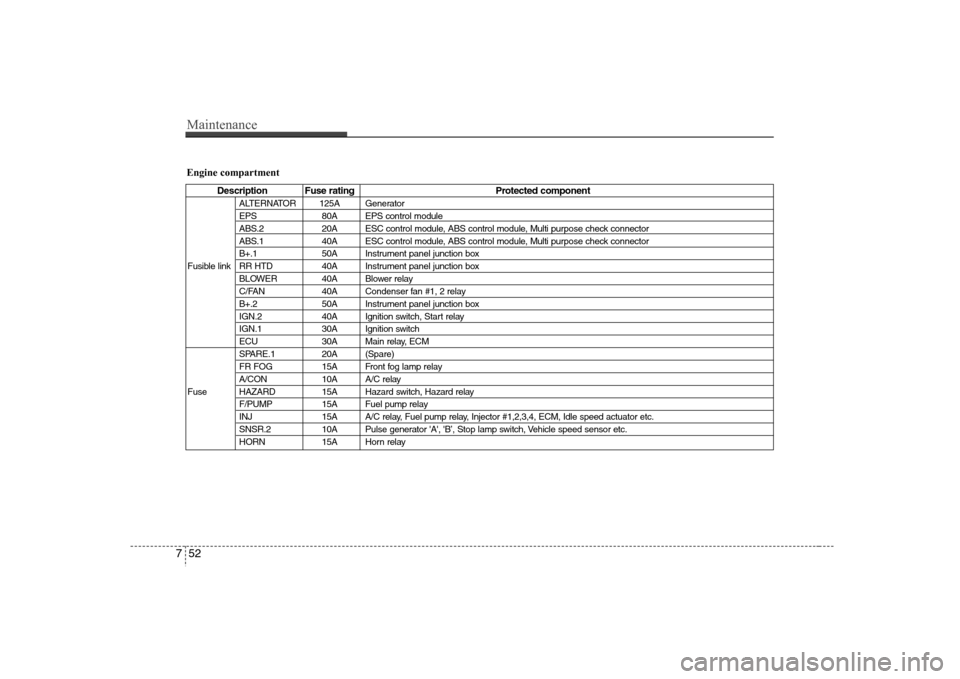
Maintenance52 7Engine compartment
Description Fuse rating Protected component
ALTERNATOR 125A Generator
EPS 80A EPS control module
ABS.2 20A ESC control module, ABS control module, Multi purpose check connector
ABS.1 40A ESC control module, ABS control module, Multi purpose check connector
B+.1 50A Instrument panel junction box
Fusible link RR HTD 40A Instrument panel junction box
BLOWER 40A Blower relay
C/FAN 40A Condenser fan #1, 2 relay
B+.2 50A Instrument panel junction box
IGN.2 40A Ignition switch, Start relay
IGN.1 30A Ignition switch
ECU 30A Main relay, ECM
SPARE.1 20A (Spare)
FR FOG 15A Front fog lamp relay
A/CON 10A A/C relay
Fuse HAZARD 15A Hazard switch, Hazard relay
F/PUMP 15A Fuel pump relay
INJ 15A A/C relay, Fuel pump relay, Injector #1,2,3,4, ECM, Idle speed actuator etc.
SNSR.2 10A Pulse generator 'A', 'B’, Stop lamp switch, Vehicle speed sensor etc.
HORN 15A Horn relay