clock HYUNDAI ELANTRA GT 2020 User Guide
[x] Cancel search | Manufacturer: HYUNDAI, Model Year: 2020, Model line: ELANTRA GT, Model: HYUNDAI ELANTRA GT 2020Pages: 495, PDF Size: 15.22 MB
Page 367 of 495
6-16
What to do in an emergency
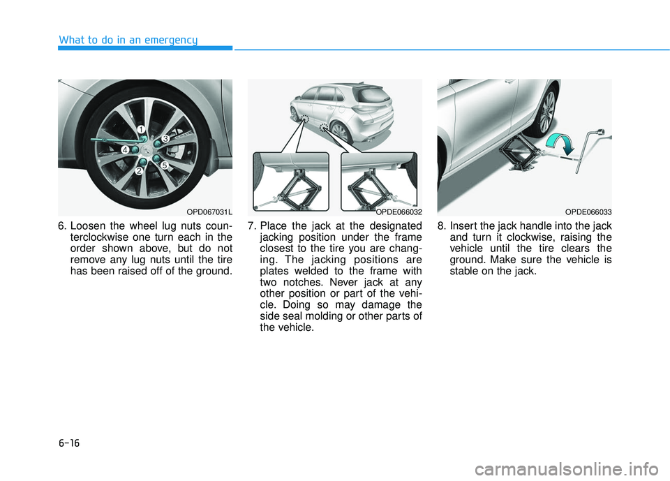
6. Loosen the wheel lug nuts coun- terclockwise one turn each in the
order shown above, but do not
remove any lug nuts until the tire
has been raised off of the ground. 7. Place the jack at the designated
jacking position under the frame
closest to the tire you are chang-
ing. The jacking positions are
plates welded to the frame with
two notches. Never jack at any
other position or part of the vehi-
cle. Doing so may damage the
side seal molding or other parts of
the vehicle. 8. Insert the jack handle into the jack
and turn it clockwise, raising the
vehicle until the tire clears the
ground. Make sure the vehicle is
stable on the jack.
OPD067031LOPDE066032OPDE066033
Page 368 of 495
6-17
What to do in an emergency
6
9. Loosen the lug nuts with the wheellug nut wrench and remove them
with your fingers. Remove the
wheel from the studs and lay it flat
on the ground out of the way.
Remove any dirt or debris from
the studs, mounting surfaces, and
wheel.
10. Install the spare tire onto the studs of the hub.
11. Tighten the lug nuts with your fin- gers onto the studs with the
smaller end of the lug nuts clos-
est to the wheel.
12. Lower the vehicle to the ground by turning the jack handle coun-
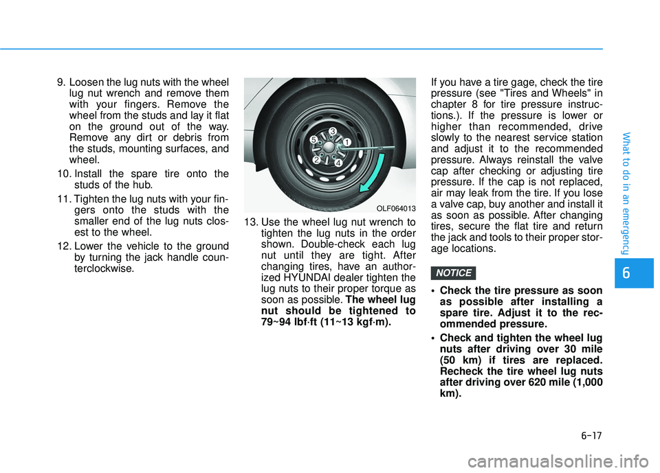
terclockwise. 13. Use the wheel lug nut wrench to
tighten the lug nuts in the order
shown. Double-check each lug
nut until they are tight. After
changing tires, have an author-
ized HYUNDAI dealer tighten the
lug nuts to their proper torque as
soon as possible. The wheel lug
nut should be tightened to
79~94 lbf·ft (11~13 kgf·m). If you have a tire gage, check the tire
pressure (see "Tires and Wheels" in
chapter 8 for tire pressure instruc-
tions.). If the pressure is lower or
higher than recommended, drive
slowly to the nearest service station
and adjust it to the recommended
pressure. Always reinstall the valve
cap after checking or adjusting tire
pressure. If the cap is not replaced,
air may leak from the tire. If you lose
a valve cap, buy another and install it
as soon as possible. After changing
tires, secure the flat tire and return
the jack and tools to their proper stor-
age locations.
Check the tire pressure as soon
as possible after installing a
spare tire. Adjust it to the rec-
ommended pressure.
Check and tighten the wheel lug nuts after driving over 30 mile
(50 km) if tires are replaced.
Recheck the tire wheel lug nuts
after driving over 620 mile (1,000
km).
NOTICE
OLF064013
Page 372 of 495
6-21
What to do in an emergency
6
When towing your vehicle in an
emergency without wheel dollies:
1.Place the ignition switch in theACC position.
2.Place the shift lever in N (Neutral).
3.Release the parking brake.
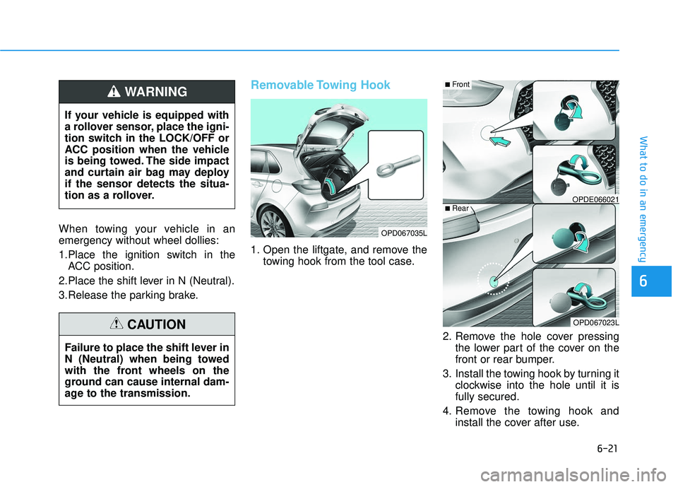
Removable Towing Hook
1. Open the liftgate, and remove the towing hook from the tool case.
2. Remove the hole cover pressingthe lower part of the cover on the
front or rear bumper.
3. Install the towing hook by turning it clockwise into the hole until it is
fully secured.
4. Remove the towing hook and install the cover after use.
If your vehicle is equipped with
a rollover sensor, place the igni-
tion switch in the LOCK/OFF or
ACC position when the vehicle
is being towed. The side impact
and curtain air bag may deploy
if the sensor detects the situa-
tion as a rollover.
WARNING
Failure to place the shift lever in
N (Neutral) when being towed
with the front wheels on the
ground can cause internal dam-
age to the transmission.
CAUTION
OPD067035L
OPDE066021
OPD067023L
■Front
■Rear
Page 399 of 495
7-25
7
MaintenanceThe electric motor for the cooling fan
is controlled by engine coolant tem-
perature, refrigerant pressure and
vehicle speed. As the engine coolant
temperature decreases, the electric
motor will automatically shut off. This
is a normal condition. If your vehicle
is equipped with GDI, the electric
motor for the cooling fan may begin
to operate at any time and continue
to operate until you disconnect the
negative battery cable.The electric motor for
the cooling fan may
continue to operate
or start up when the
engine is not running
and can cause serious injury.
Keep hands, clothing and tools
away from the rotating fan
blades of the cooling fan.
WARNING
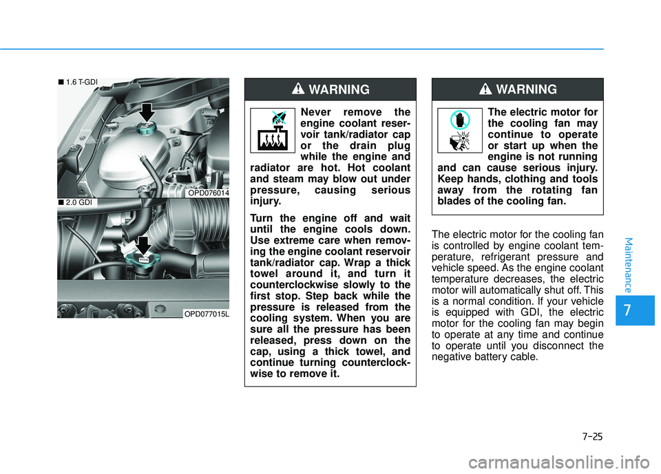
Never remove the
engine coolant reser-
voir tank/radiator cap
or the drain plug
while the engine and
radiator are hot. Hot coolant
and steam may blow out under
pressure, causing serious
injury.
Turn the engine off and wait
until the engine cools down.
Use extreme care when remov-
ing the engine coolant reservoir
tank/radiator cap. Wrap a thick
towel around it, and turn it
counterclockwise slowly to the
first stop. Step back while the
pressure is released from the
cooling system. When you are
sure all the pressure has been
released, press down on the
cap, using a thick towel, and
continue turning counterclock-
wise to remove it.
WARNING
OPD076014
OPD077015L
■ 1.6 T-GDI
■2.0 GDI
Page 411 of 495
7-37
7
Maintenance
By jump starting
After a jump start from a good bat-
tery, drive the vehicle for 20-30 min-
utes before it is shutoff. The vehicle
may not restart if you shut it off
before the battery had a chance to
adequately recharge. See "Jump
Starting" in chapter 6 for more infor-
mation on jump starting procedures.
Information
An inappropriately disposedbattery can be harmful to
the environment and human
health. Dispose of the bat-
tery according to your local
law(s) or regulations.
Reset Features
The following items may need to be
reset after the battery has been dis-
charged or the battery has been dis-
connected. See chapter 3 or 4 for:
Power Windows
Trip Computer
Climate Control System
Clock
Audio System
Sunroof
i
(Continued)
Watch the battery during
charging, and stop or reduce
the charging rate if the battery
cells begin boiling violently.
The negative battery cable
must be removed first and
installed last when the battery
is disconnected. Disconnect
the battery charger in the fol-
lowing order:
(1) Turn off the battery charg- er main switch.
(2) Unhook the negative
clamp from the negative
battery terminal.
(3) Unhook the positive clamp from the positive battery
terminal.
Always use a genuine
HYUNDAI approved battery
when you replace the battery.
Page 431 of 495
7-57
7
Maintenance
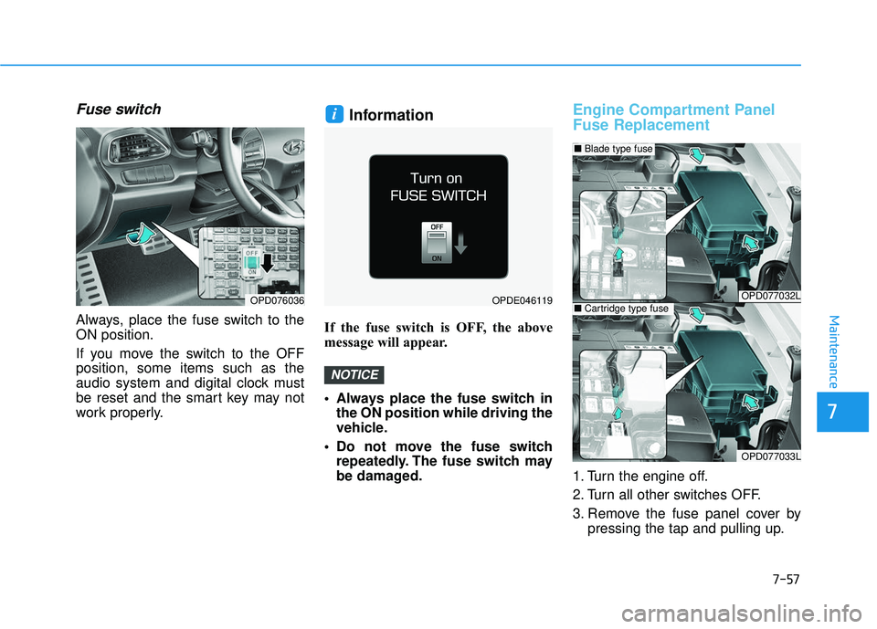
Fuse switch
Always, place the fuse switch to the
ON position.
If you move the switch to the OFF
position, some items such as the
audio system and digital clock must
be reset and the smart key may not
work properly.
Information
If the fuse switch is OFF, the above
message will appear.
Always place the fuse switch inthe ON position while driving the
vehicle.
Do not move the fuse switch repeatedly. The fuse switch may
be damaged.
Engine Compartment Panel
Fuse Replacement
1. Turn the engine off.
2. Turn all other switches OFF.
3. Remove the fuse panel cover by pressing the tap and pulling up.
NOTICE
i
OPD076036OPDE046119OPD077032L
OPD077033L
■Blade type fuse
■Cartridge type fuse
Page 445 of 495
7-71
7
Maintenance
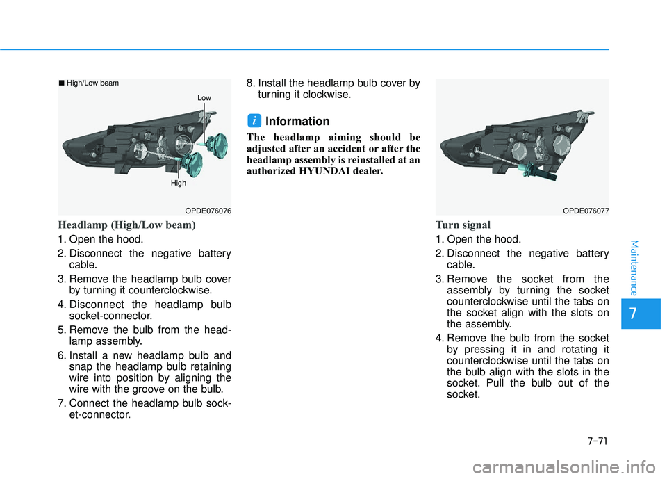
Headlamp (High/Low beam)
1. Open the hood.
2. Disconnect the negative batterycable.
3. Remove the headlamp bulb cover by turning it counterclockwise.
4. Disconnect the headlamp bulb socket-connector.
5. Remove the bulb from the head- lamp assembly.
6. Install a new headlamp bulb and snap the headlamp bulb retaining
wire into position by aligning the
wire with the groove on the bulb.
7. Connect the headlamp bulb sock- et-connector. 8. Install the headlamp bulb cover by
turning it clockwise.
Information
The headlamp aiming should be
adjusted after an accident or after the
headlamp assembly is reinstalled at an
authorized HYUNDAI dealer.
Turn signal
1. Open the hood.
2. Disconnect the negative batterycable.
3. Remove the socket from the assembly by turning the socket
counterclockwise until the tabs on
the socket align with the slots on
the assembly.
4. Remove the bulb from the socket by pressing it in and rotating it
counterclockwise until the tabs on
the bulb align with the slots in the
socket. Pull the bulb out of the
socket.
i
OPDE076077OPDE076076
■High/Low beam
High
Low
Page 446 of 495
7-72
Maintenance
5. Install a new bulb by inserting it into the socket and rotating it until
it locks into place.
6. Install the socket in the assembly by aligning the tabs on the socket
with the slots in the assembly.
7. Push the socket into the assembly and turn the socket clockwise.
Parking lamp and daytime running
light
Your vehicle is equipped with LED
lamps. LED lamps do not have
replaceable bulbs. If the LED lamp
does not operate, have the vehicle
checked by an authorized HYUNDAI
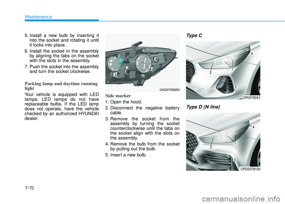
dealer.Side marker
1. Open the hood.
2. Disconnect the negative batterycable.
3. Remove the socket from the assembly by turning the socket
counterclockwise until the tabs on
the socket align with the slots on
the assembly.
4. Remove the bulb from the socket by pulling out the bulb.
5. Insert a new bulb.
Type C
Type D (N line)
OAD075082N
OPD076041
OPDE078130
Page 449 of 495
7-75
7
Maintenance
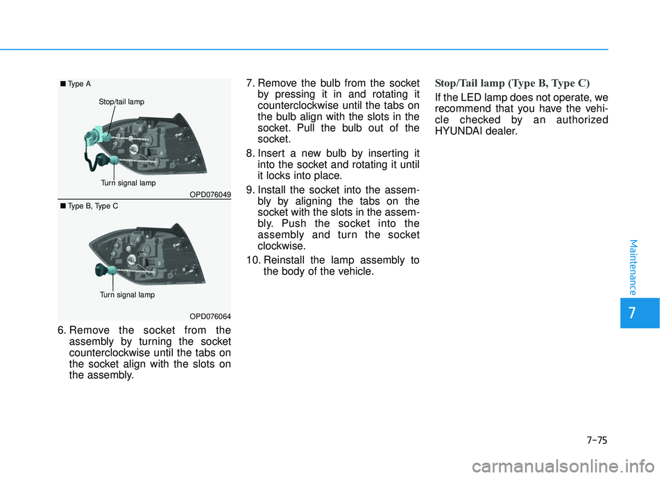
6. Remove the socket from theassembly by turning the socket
counterclockwise until the tabs on
the socket align with the slots on
the assembly. 7. Remove the bulb from the socket
by pressing it in and rotating it
counterclockwise until the tabs on
the bulb align with the slots in the
socket. Pull the bulb out of the
socket.
8. Insert a new bulb by inserting it into the socket and rotating it until
it locks into place.
9. Install the socket into the assem- bly by aligning the tabs on the
socket with the slots in the assem-
bly. Push the socket into the
assembly and turn the socket
clockwise.
10. Reinstall the lamp assembly to the body of the vehicle.
Stop/Tail lamp (Type B, Type C)
If the LED lamp does not operate, we
recommend that you have the vehi-
cle checked by an authorized
HYUNDAI dealer.
OPD076049
Stop/tail lamp
Turn signal lamp
OPD076064
Turn signal lamp
■Type A
■Type B, Type C
Page 450 of 495
7-76
Maintenance
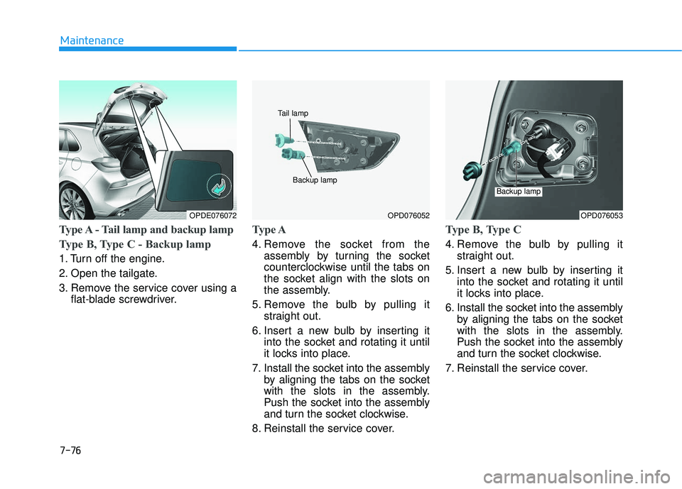
Type A - Tail lamp and backup lamp
Type B, Type C - Backup lamp
1. Turn off the engine.
2. Open the tailgate.
3. Remove the service cover using aflat-blade screwdriver.
Type A
4. Remove the socket from theassembly by turning the socket
counterclockwise until the tabs on
the socket align with the slots on
the assembly.
5. Remove the bulb by pulling it straight out.
6. Insert a new bulb by inserting it into the socket and rotating it until
it locks into place.
7. Install the socket into the assembly by aligning the tabs on the socket
with the slots in the assembly.
Push the socket into the assembly
and turn the socket clockwise.
8. Reinstall the service cover.
Type B, Type C
4. Remove the bulb by pulling it straight out.
5. Insert a new bulb by inserting it into the socket and rotating it until
it locks into place.
6. Install the socket into the assembly by aligning the tabs on the socket
with the slots in the assembly.
Push the socket into the assembly
and turn the socket clockwise.
7. Reinstall the service cover.
OPD076052
Backup lamp
Tail lamp
OPD076053
Backup lamp
OPDE076072