roof HYUNDAI ELANTRA HYBRID 2022 User Guide
[x] Cancel search | Manufacturer: HYUNDAI, Model Year: 2022, Model line: ELANTRA HYBRID, Model: HYUNDAI ELANTRA HYBRID 2022Pages: 529, PDF Size: 38.79 MB
Page 191 of 529

Convenient Features
5-44
Tilt Open/Close
OCN7051144L
• Push the sunroof switch upward, the
sunroof glass tilts open.
• Push the sunroof switch forward when
the sunroof glass is tilt opened, the
sunroof glass closes.
The sunroof glass tilts open or closes
while the switch is pushed.
Information
The sunroof glass cannot slide open and
tilt open at the same time. You cannot tilt
the sunroof glass open while the sunroof
glass is slide open. Also, you cannot slide
the sunroof glass open while the sunroof
is tilt open. Slide open or tilt open with
the sunroof glass when the sunroof glass is completely closed.
Slide Open/Close
OCN7051031L
• Push the sunroof switch rearward,
the sunshade and sunroof glass slide open.
Push the sunroof switch forward, only
the sunroof glass closes.
• Push the sunroof switch forward or
rearward to the first detent position,
the sunroof glass moves until the
switch is released.
• Push the sunroof switch forward
or rearward to the second detent
position, the sunroof glass operates
automatically (auto slide feature).
To stop the sunroof movement at any
point, push the sunroof switch in any
direction.
• The sunroof glass stops halfway
(first detent position) before it is fully
opened. To fully open the sunroof
glass, push the sunroof switch
rearward once more. At this time, the
sunroof glass opens only while the
switch is pushed.
Information
To reduce wind noise while driving, have
you drive at the recommended position
(first detent position) before the maximum slide open position.
Page 192 of 529

05
5-45
Automatic Reversal (if equipped)
OCN7050030
If the sunroof glass senses any obstacle
while it is closing automatically, it will
reverse direction then stop at a certain position.
The auto reverse function may not
work if an object thin or soft is caught
between the sliding sunroof glass and
sunroof sash.
To close the sunroof:
Press the sunroof lever forward until the
sunroof moves to the desired position.
WARNING
• Make sure heads, hands, arms or
any other body parts or objects are
out of the way before operating the
sunroof. Body parts or objects may
get caught causing injuries or vehicle damage.
• Never deliberately use your body
parts to test the automatic reversal
function. The sunroof glass may
reverse direction, but there is a risk
of injury.
NOTICE
• Do not continue to push the sunroof
switch after the sunroof is fully
opened, closed, or tilted. Damage to
the sunroof motor could occur.
• Continuous operations such as slide
open/close, tilt open/close, etc. may
cause the motor or sunroof system to malfunction.
• Regularly remove any accumulated
dust on the sunroof rail.
• Dust accumulated between the
sunroof and roof panel can make
noise Open the sunroof and remove
dust regularly using a clean cloth.
• Do not try to open the sunroof when
the temperature is below freezing
or when the sunroof is covered
with snow or ice. The sunroof may
not work properly and may break if
opened by force.
• Do not open or drive with the sunroof
glass open immediately after rain or
washing the vehicle. Water may wet
the interior of the vehicle.
• Do not extend any luggage outside
the sunroof while driving. Vehicle
damage may occur if the vehicle
suddenly stops.
WARNING
Do not extend your head, arms, body
parts or objects outside the sunroof
while driving. Injuries may occur if the
vehicle suddenly stops.
Page 193 of 529

Convenient Features
5-46
Resetting the Sunroof
OCN7051028L
In some circumstances resetting the
sunroof operation may need to be
performed. Some instances where
resetting the sunroof may be required include: • When the 12-volt battery is either
disconnected or discharged
• When the sunroof fuse is replaced
• If the sunroof one-touch AUTO OPEN/
CLOSE operation is not functioning
properly
Sunroof resetting procedure:
1. It is recommended to perform the reset procedure with the vehicle
engine running. Start the vehicle in P
(Park).
2. Make sure the sunroof glass is in the fully closed position. If the sunroof
glass is open, push the switch forward
until the sunroof glass is fully closed.
3. Release the switch when the sunroof glass is fully closed.
4. Push the switch forward until the
sunroof glass moves slightly. Then
release the switch. 5. Once again push and hold the sunroof
switch forward until the sunroof glass
slides open and close. Do not release
the switch until the operation is
completed.
If you release the switch during
operation, start the procedure again
from step 2.
Information
If the sunroof is not reset when the vehicle
battery is disconnected or discharged, or
the sunroof fuse is blown, the sunroof may
not operate normally.
Sunroof Open Warning (if equipped)
OCN7040018
If the driver turns off the engine when
the sunroof is not fully closed, the
warning chime will sound for several
seconds and the sunroof open warning
will appear on the cluster LCD display.
Close the sunroof securely when leaving
your vehicle.
CAUTION
Make sure the sunroof is closed fully
when leaving your vehicle.
If the sunroof is left open, rain or snow
may wet the interior of the vehicle.
Also, leaving the sunroof open when the
vehicle is unattended may invite theft.
Page 225 of 529
Convenient Features
5-78
Air conditioning system operation tips
• If the vehicle has been parked in
direct sunlight during hot weather,
open the windows for a short time
to let the hot air inside the vehicle escape.
• After sufficient cooling has been
achieved, switch back from
recirculation mode to fresh mode.
• To help reduce moisture inside of
the windows on rainy or humid
days, decrease the humidity inside
the vehicle by operating the air
conditioning system with the windows
and sunroof closed.
• During air conditioning system
operation, you may occasionally
notice a slight change in engine speed
as the air conditioning compressor
cycles. This is a normal system
operation characteristic.
• Use the air conditioning system
every month only for a few minutes
to ensure maximum system
performance.
• When using the air conditioning
system, you may notice clear water
dripping (or even puddling) on the
ground under the passenger side of
the vehicle. This is a normal system
operation characteristic.
• If you operate the air conditioner
excessively, the difference between
the temperature of the outside air and
that of the windshield could cause
the outer surface of the windshield to
fog up, causing loss of visibility. In this
case, set the mode selection button to the
position and set the fan speed
control knob to the lowest speed
setting.
System Maintenance
Cabin air filter
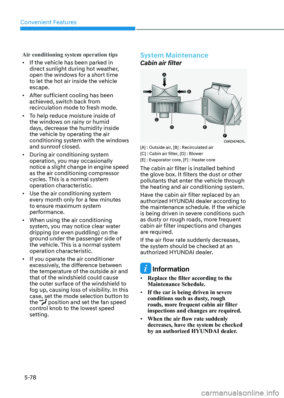
OIK047401L
[A] : Outside air, [B] : Recirculated air
[C] : Cabin air filter, [D] : Blower
[E] : Evaporator core, [F] : Heater core
The cabin air filter is installed behind
the glove box. It filters the dust or other
pollutants that enter the vehicle through
the heating and air conditioning system.
Have the cabin air filter replaced by an
authorized HYUNDAI dealer according to
the maintenance schedule. If the vehicle
is being driven in severe conditions such
as dusty or rough roads, more frequent
cabin air filter inspections and changes
are required.
If the air flow rate suddenly decreases,
the system should be checked at an
authorized HYUNDAI dealer.
Information
• Replace the filter according to the Maintenance Schedule.
• If the car is being driven in severe
conditions such as dusty, rough
roads, more frequent cabin air filter
inspections and changes are required.
• When the air flow rate suddenly
decreases, have the system be checked
by an authorized HYUNDAI dealer.
Page 232 of 529
05
5-85
Sunroof Inside Air Recirculation (if equipped)
When the sunroof is opened, outside
(fresh) air will be automatically selected.
At this time, if you press the air intake
control button, recirculated air position
will be selected but will change back
to outside (fresh) air after 3 minutes.
When the sunroof is closed, the air
intake position will return to the original
position that was selected.
Auto Comfort Control
(for driver’s seat) (if equipped)
The temperature of the driver’s seat
warmer, air ventilation seat and
heated steering wheel is automatically
controlled depending on the inside and
outside temperature of the vehicle when the engine is running.
To use this function, it must be
activated from the Settings menu in the
Infotainment system screen. Select: - All menus → Setup → Vehicle → Heated
/ Ventilated Features
For more details on Auto Comfort
Control, refer to “Seat warmers and
air ventilation seat” in chapter 3, and
“Heated steering wheel” in chapter 5
Automatic Ventilation (if equipped)
The system automatically selects the
fresh mode when the climate control
system operates over a certain period of
time (approximately 30 minutes) in low
temperature with the recirculation mode
selected.
To cancel or reactivate the
Automatic Ventilation
When the air conditioning system is on,
select Face Level
mode and press the
air recirculation mode button at least 5
times within 3 seconds while pressing
the A/C button.
When the automatic ventilation is
canceled, the indicator blinks 3 times.
When the automatic ventilation is
activated, the indicator blinks 6 times.
climate cOntROl aDDitiOnal featuReS
Page 426 of 529
08
8-5
Before Jump Starting
This vehicle does not have a regular 12V
battery that needs periodic replacement.
It is lithium ion polymer type integrated
into the HEV high voltage battery. The
vehicle has a 12V battery protection
system that cuts 12V battery from vehicle
draw to prevent full discharge.
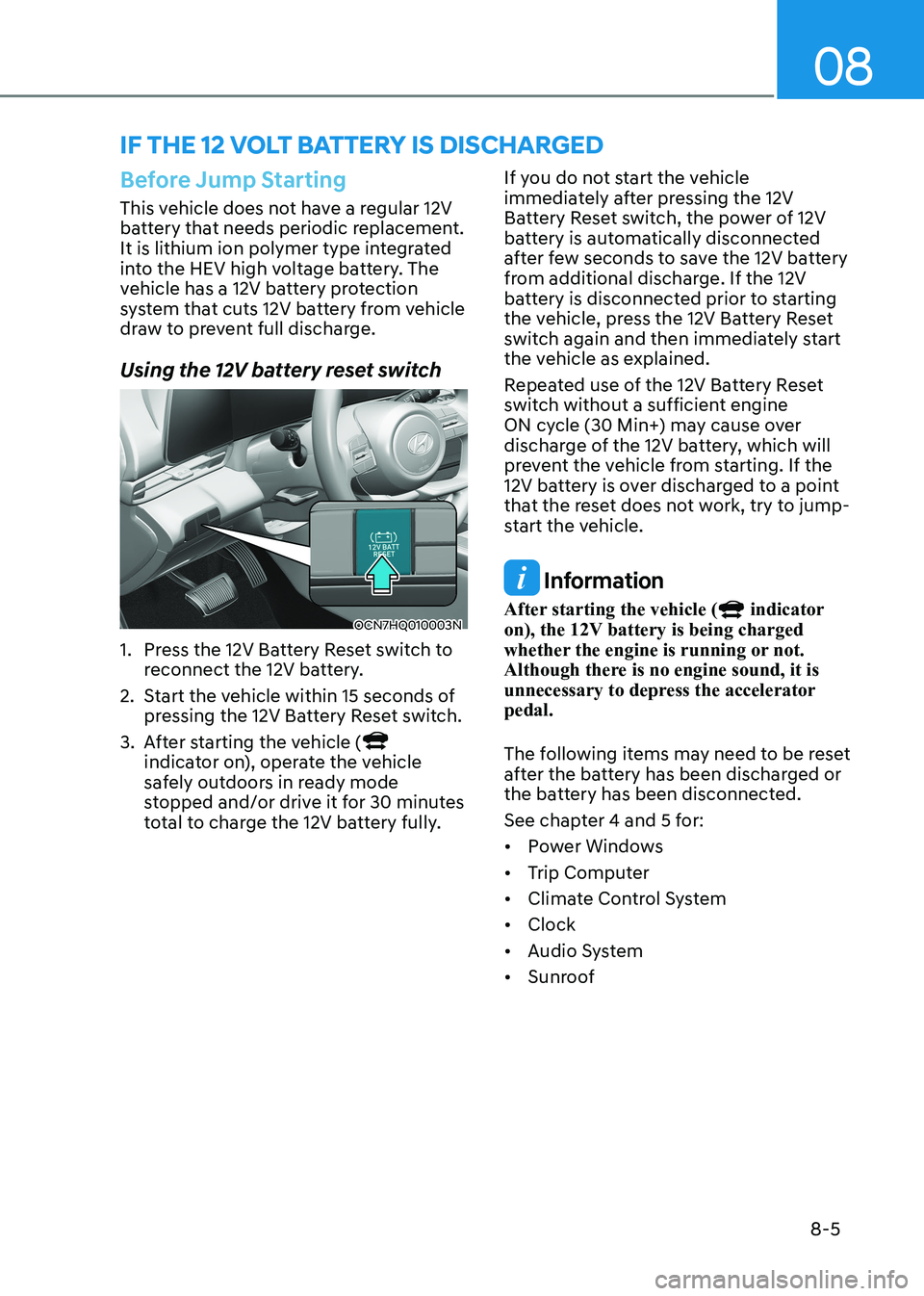
Using the 12V battery reset switch
OCN7HQ010003N
1. Press the 12V Battery Reset switch to reconnect the 12V battery.
2. Start the vehicle within 15 seconds of pressing the 12V Battery Reset switch.
3. After starting the vehicle (
indicator on), operate the vehicle
safely outdoors in ready mode
stopped and/or drive it for 30 minutes
total to charge the 12V battery fully. If you do not start the vehicle
immediately after pressing the 12V
Battery Reset switch, the power of 12V
battery is automatically disconnected
after few seconds to save the 12V battery
from additional discharge. If the 12V
battery is disconnected prior to starting
the vehicle, press the 12V Battery Reset
switch again and then immediately start
the vehicle as explained.
Repeated use of the 12V Battery Reset
switch without a sufficient engine
ON cycle (30 Min+) may cause over
discharge of the 12V battery, which will
prevent the vehicle from starting. If the
12V battery is over discharged to a point
that the reset does not work, try to jump-
start the vehicle.
Information
After starting the vehicle (
indicator
on), the 12V battery is being charged
whether the engine is running or not.
Although there is no engine sound, it is
unnecessary to depress the accelerator pedal.
The following items may need to be reset
after the battery has been discharged or
the battery has been disconnected.
See chapter 4 and 5 for:• Power Windows
• Trip Computer
• Climate Control System
• Clock
• Audio System
• Sunroof
iF tHe 12 volt Battery is disCHarged
Page 487 of 529

Maintenance
9-38
Pneumatic tire
A mechanical device made of rubber,
chemicals, fabric and steel or other
materials, that, when mounted on
an automotive wheel provides the
traction and contains the gas or fluid
that sustains the load.
Pneumatic options weight
The combined weight of installed
regular production options weighing
over 2.3 kg (5 lb.) in excess of the
standard items which they replace,
not previously considered in
curb weight or accessory weight,
including heavy duty breaks, ride
levelers, roof rack, heavy duty
battery, and special trim.
Recommended Inflation Pressure
Vehicle manufacturer’s
recommended tire inflation pressure
as shown on the tire placard.
Radial Ply Tire
A pneumatic tire in which the ply
cords that extend to the beads are
laid at 90 degrees to the centerline
of the tread. Rim
A metal support for a tire and upon
which the tire beads are seated.
Sidewall
The portion of a tire between the
tread and the bead.
Speed Rating
An alphanumeric code assigned to a
tire indicating the maximum speed
at which a tire can operate.
Traction
The friction between the tire and
the road surface. The amount of grip
provided.
Tread
The portion of a tire that comes into
contact with the road.
Treadwear Indicators
Narrow bands, sometimes called
“wear bars”, that show across the
tread of a tire when only 1.6 mm (1/16
inch) of tread remains.
UTQGS
Uniform Tire Quality Grading
Standards is a tire information
system that provides consumers
with ratings for a tire’s traction,
temperature and treadwear.
Ratings are determined by tire
manufacturers using government
testing procedures. The ratings are
molded into the sidewall of the tire.
Vehicle Capacity Weight
The number of designated seating
positions multiplied by 68 kg (150
lbs.) plus the rated cargo and luggage load.
Vehicle Maximum Load on the Tire
Load on an individual tire due to curb
and accessory weight plus maximum
occupant and cargo weight.
Vehicle Normal Load on the Tire
Load on an individual tire that is
determined by distributing to each
axle its share of the curb weight,
accessory weight, and normal
occupant weight and dividing by 2.
Vehicle Placard
A label permanently attached
to a vehicle showing the
original equipment tire size and
recommended inflation pressure.
Page 495 of 529

Maintenance
9-46
Driver’s side fuse panel
Fuse Name Fuse Rating Circuit Protected
MODULE2 10AE/R Junction Block (Power Outlet Relay), AMP, IBU,
IAU, Audio, Power Outside Mirror Switch, DC-DC
Converter (Smartstream G 2.0 Atkinson ISG only),
A/V & Navigation Head Unit
AIR BAG1 15ASRS Control Module, Passenger Occupant Detection Sensor
MODULE5 10AA/T Shift Lever Indicator, Front Wireless Charger,
A/C Controller, Electro Chromic Mirror, A/C Control
Module, Audio, A/V & Navigation Head Unit, AMP,
DC-DC Converter (Smartstream G 2.0 Atkinson ISG
only), Data Link Connector, Rear Seat Warmer Control
Module, Front Seat Warmer Control Module
AMP 25AAMP, DC-DC Converter (Smartstream G 2.0 Atkinson
ISG only)
HEATED MIRROR 10ADriver/Passenger Outside Mirror Heated, A/C Control
Module, A/C Controller, ECU (N Line only)
DOOR LOCK 20A Door Lock/Unlock Actuator
IAU 10A BLE Unit, IAU, Driver/Passenger Door NFC Module
MODULE3 7.5A Sport Mode Switch, Stop Lamp Switch, IAU
A/BAG IND 7.5A Instrument Cluster, Overhead Console Lamp
WASHER 15A Multifunction Switch
P/SEAT PASS 30A Passenger Power Seat
P/SEAT DRV 30A Passenger Power Seat
WIPER 10A PCM/ECM, IBU
MODULE1 10ADriver/Passenger Smart Key Outside Handle, Crash
Pad Switch, Sport Mode Switch, Data Link Connector,
Hazard Switch, Key Solenoid
SUNROOF 20A Sunroof Motor
USB CHARGER 15A Front USB Charger
IG1 25A PCB Block (Fuse - ABS3, ECU5, EOP2, TCU2)
Page 498 of 529

09
9-49
Fuse Name Fuse Rating Circuit Protected
FUSEBATTERY C/
FAN 1 15A Battery C/Fan Relay
IEB1 40A IDB Unit, Multipurpose Check Connector
CLUTCH
ACTUATOR 30A Clutch Actuator
POWER
OUTLET 1 40A Power Outlet Relay
EWP 2 10A Auxiliary Electric Water Pump
EWP 1 10A Electric Water Pump
POWER
OUTLET 2 20A Front Power Outlet
DCT 1 40A TCM
DCT 2 40A TCM
REAR
HEATED 40A Rear Heated Relay
B+4 40AICU Junction Block (Power Window Relay,
Fuse - AIR BAG 2, IBU 1, BRAKE SWITCH,
DOOR LOCK, MODULE 1, SUNROOF, IAU, BMS)
HEV ECU 1 10A HPCU
IG3 20A IG3 Relay
TCU 1 10A TCM
FUEL PUMP 20A Fuel Pump Relay
HEV ECU 2 10A HPCU, BMS Control Module
Sub Block FUSE BATTERY C/
FAN 2 10A Battery C/Fan Relay
Page 520 of 529

I
I-3
Brake System ....................................................................................................... 6-24
Auto Hold ......................................................................................................... 6-29
Disc Brakes Wear Indicator .............................................................................. 6-24
Electronic Parking Brake (EPB) ...................................................................... 6-25
Power Brakes .................................................................................................... 6-24
Brake/Clutch Fluid .............................................................................................. 9-20
Checking the Brake/Clutch Fluid Level ...........................................................9-20
Bulb Wattage .......................................................................................................... 2-8
CABIN Air Filter ................................................................................................. 9-24
Filter Inspection ................................................................................................ 9-24
Filter Replacement ........................................................................................... 9-24
C Child Restraint System (CRS) ............................................................................. 3-28
Children Always in the Rear ............................................................................ 3-28
Installing a Child Restraint System (CRS) .......................................................3-30
Selecting a Child Restraint System (CRS) .......................................................3-29
Climate Control Additional Features ................................................................... 5-85
Auto Comfort Control (for driver’s seat) ........................................................5-85
Automatic Ventilation ...................................................................................... 5-85
Sunroof Inside Air Recirculation ...................................................................... 5-85
Coasting Guide .................................................................................................... 6-23
Cruise Control (CC) ............................................................................................ 7-61
DDeclaration of Conormity .................................................................................. 7-124
Dimensions ............................................................................................................ 2-7
Door Locks .......................................................................................................... 5-16
Automatic Door Lock and Unlock Features ....................................................5-20
Child-Protector Rear Door Locks .................................................................... 5-20
Operating Door Locks from Inside the Vehicle................................................ 5-17
Operating Door Locks from Outside the Vehicle .............................................5-16
Drive Mode Integrated Control System ............................................................... 6-38
Drive Mode ...................................................................................................... 6-38
Smart shift on trip computer ............................................................................. 6-41
Driver Attention Warning (DAW) ...................................................................... 7-55
Detecting sensor ............................................................................................... 7-55
Limitations of Driver Attention Warning ........................................................7-58
Driver position memory system........................................................................... 5-23