turn signal Hyundai Elantra Touring 2012 Owner's Manual
[x] Cancel search | Manufacturer: HYUNDAI, Model Year: 2012, Model line: Elantra Touring, Model: Hyundai Elantra Touring 2012Pages: 402, PDF Size: 5.49 MB
Page 13 of 402
Introduction
61
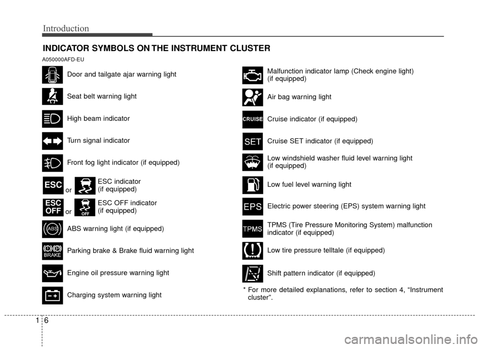
INDICATOR SYMBOLS ON THE INSTRUMENT CLUSTER
A050000AFD-EU
Door and tailgate ajar warning light
Seat belt warning light
High beam indicator
Turn signal indicator
Front fog light indicator (if equipped)
ABS warning light (if equipped)
Parking brake & Brake fluid warning light
Engine oil pressure warning light
Charging system warning light
Malfunction indicator lamp (Check engine light)
(if equipped)
Air bag warning light
Cruise indicator (if equipped)
Cruise SET indicator (if equipped)
Low fuel level warning light
Electric power steering (EPS) system warning light
Low windshield washer fluid level warning light
(if equipped)
* For more detailed explanations, refer to section 4, “Instrument cluster”.
TPMS (Tire Pressure Monitoring System) malfunction
indicator (if equipped)
Low tire pressure telltale (if equipped)
Shift pattern indicator (if equipped)
ESC
ESCOFF
ESC indicator
(if equipped)
ESC OFF indicator
(if equipped)
or
or
Page 16 of 402
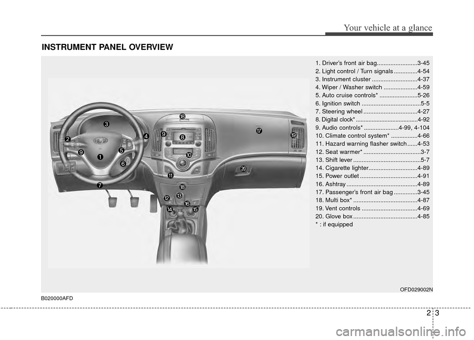
INSTRUMENT PANEL OVERVIEW
1. Driver’s front air bag........................3-45
2. Light control / Turn signals ..............4-54
3. Instrument cluster ...........................4-37
4. Wiper / Washer switch ....................4-59
5. Auto cruise controls* .......................5-26
6. Ignition switch ...................................5-5
7. Steering wheel ................................4-27
8. Digital clock* .......................................4-92
9. Audio controls* .....................4-99, 4-104
10. Climate control system* ................4-66
11. Hazard warning flasher switch ......4-53
12. Seat warmer* ..................................3-7
13. Shift lever ........................................5-7
14. Cigarette lighter.............................4-89
15. Power outlet ..................................4-91
16. Ashtray ..........................................4-89
17. Passenger’s front air bag ..............3-45
18. Multi box* ......................................4-87
19. Vent controls .................................4-69
20. Glove box ......................................4-85
* : if equipped
OFD029002N
B020000AFD
23
Your vehicle at a glance
Page 52 of 402
335
Safety features of your vehicle
C040900AEN-EU
How does the air bag system
operate
Air bags are activated (able to inflate ifnecessary) only when the ignition
switch is turned to the ON or START
position.
Air bags inflate instantly in the event of serious frontal or side collision (if
equipped with side air bag or curtain
air bag) in order to help protect the
occupants from serious physical injury.
There is no single speed at which the air bags will inflate.
Generally, air bags are designed to
inflate by the severity of a collision and
its direction. These two factors deter-
mine whether the sensors produce an
electronic deployment/inflation signal.
Air bag deployment depends on a number of factors including vehicle
speed, angles of impact and the densi-
ty and stiffness of the vehicles or
objects which your vehicle hits in the
collision. The determining factors are
not limited to those mentioned above.
The front air bags will completely inflate and deflate in an instant. It is virtually impossible for you to see
the air bags inflate during an accident.
It is much more likely that you will sim-
ply see the deflated air bags hanging
out of their storage compartments after
the collision.
In order to help provide protection in a severe collision, the air bags must
inflate rapidly. The speed of air bag
inflation is a consequence of the
extremely short time in which a collision
occurs and the need to inflate the air
bag between the occupant and the
vehicle structures before the occupant
impacts those structures. This speed of
inflation reduces the risk of serious or
life-threatening injuries in a severe col-
lision and is thus a necessary part of air
bag design.
However, air bag inflation can also
cause injuries which can include facial
abrasions, bruises and broken bones,
because the inflation speed also caus-
es the air bags to expand with a great
deal of force.
There are even circumstances under which contact with the steer-
ing wheel air bag can cause fatal
injuries, especially if the occupant
is positioned excessively close to
the steering wheel.
WARNING
To avoid severe personal injuryor death caused by deploying air
bags in a collision, the driver
should sit as far back from the
steering wheel air bag as possi-
ble (at least 10 inches (250 mm)
away). The front passenger
should always move their seat as
far back as possible and sit back
in their seat.
Air bag inflates instantly in the event of collision, passengers
may be injured by the air bag
expansion force if they are not in
proper position.
Air bag inflation may cause injuries including facial or bodily
abrasions, injuries from broken
glasses or burns.
Page 107 of 402
431
Features of your vehicle
Retain the original transmitter for future
programming procedures (i.e., new vehi-
cle purchase). It is also suggested that
upon the sale of the vehicle, the pro-
grammed HomeLink buttons be erased
for security purposes (follow step 1 in the
“Programming” portion of this text).
Programming
Your vehicle may require the ignition
switch to be turned to the ACC position
for programming and/or operation of
HomeLink. It is also recommended that a
new battery be replaced in the hand-held
transmitter of the device being pro-
grammed to HomeLink for quicker train-
ing and accurate transmission of the
radio-frequency.
Follow these steps to train your
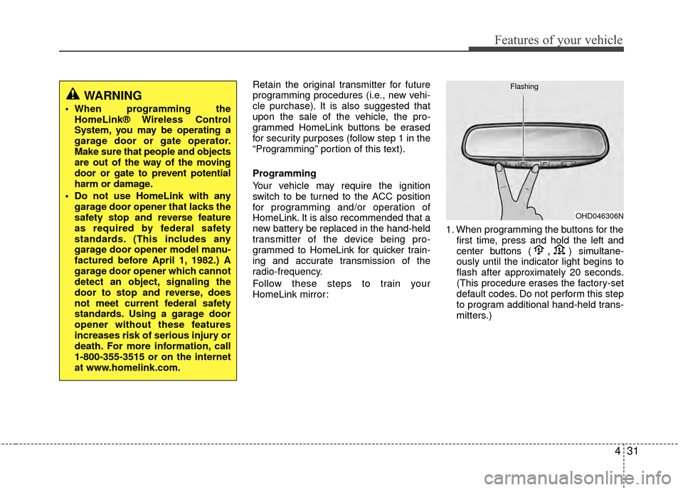
HomeLink mirror:1. When programming the buttons for the
first time, press and hold
the left and
center buttons (,)simultane-
ously until the indicator light begins to
flash after approximately 20 seconds.
(This procedure erases the factory-set
default codes. Do not perform this step
to program additional hand-held trans-
mitters.)
WARNING
When programming the HomeLink® Wireless Control
System, you may be operating a
garage door or gate operator.
Make sure that people and objects
are out of the way of the moving
door or gate to prevent potential
harm or damage.
Do not use HomeLink with any garage door opener that lacks the
safety stop and reverse feature
as required by federal safety
standards. (This includes any
garage door opener model manu-
factured before April 1, 1982.) A
garage door opener which cannot
detect an object, signaling the
door to stop and reverse, does
not meet current federal safety
standards. Using a garage door
opener without these features
increases risk of serious injury or
death. For more information, call
1-800-355-3515 or on the internet
at www.homelink.com.
OHD046306N
Flashing
Page 108 of 402
Features of your vehicle
32
4
✽
✽
NOTICE
For non rolling code garage door open-
ers, follow steps 2 - 3.
For rolling code garage door openers,
follow steps 2 - 6.
For Canadian Programming, please fol-
low the Canadian Programming section.
For help with determining whether your
garage is non-rolling code or rolling
code, please refer to the garage door
openers owner’s manual or contact
HomeLink customer service at 1-800-
355-3515.
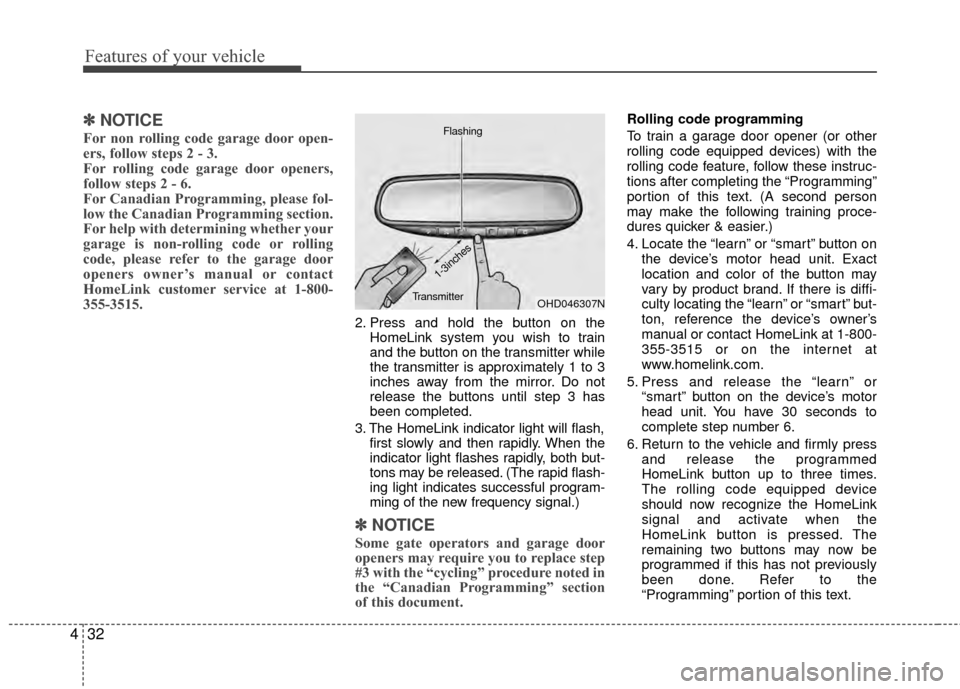
2. Press and hold the button on the
HomeLink system you wish to train
and the button on the transmitter while
the transmitter is approximately 1 to 3
inches away from the mirror. Do not
release the buttons until step 3 has
been completed.
3. The HomeLink indicator light will flash, first slowly and then rapidly. When the
indicator light flashes rapidly, both but-
tons may be released. (The rapid flash-
ing light indicates successful program-
ming of the new frequency signal.)
✽ ✽NOTICE
Some gate operators and garage door
openers may require you to replace step
#3 with the “cycling” procedure noted in
the “Canadian Programming” section
of this document.
Rolling code programming
To train a garage door opener (or other
rolling code equipped devices) with the
rolling code feature, follow these instruc-
tions after completing the “Programming”
portion of this text. (A second person
may make the following training proce-
dures quicker & easier.)
4. Locate the “learn” or “smart” button on
the device’s motor head unit. Exact
location and color of the button may
vary by product brand. If there is diffi-
culty locating the “learn” or “smart” but-
ton, reference the device’s owner’s
manual or contact HomeLink at 1-800-
355-3515 or on the internet at
www.homelink.com.
5. Press and release the “learn” or “smart” button on the device’s motor
head unit. You have 30 seconds to
complete step number 6.
6. Return to the vehicle and firmly press and release the programmed
HomeLink button up to three times.
The rolling code equipped device
should now recognize the HomeLink
signal and activate when the
HomeLink button is pressed. The
remaining two buttons may now be
programmed if this has not previously
been done. Refer to the
“Programming” portion of this text.
OHD046307N
Flashing
1-3inches
Transmitter
Page 113 of 402
437
Features of your vehicle
D150000AFD
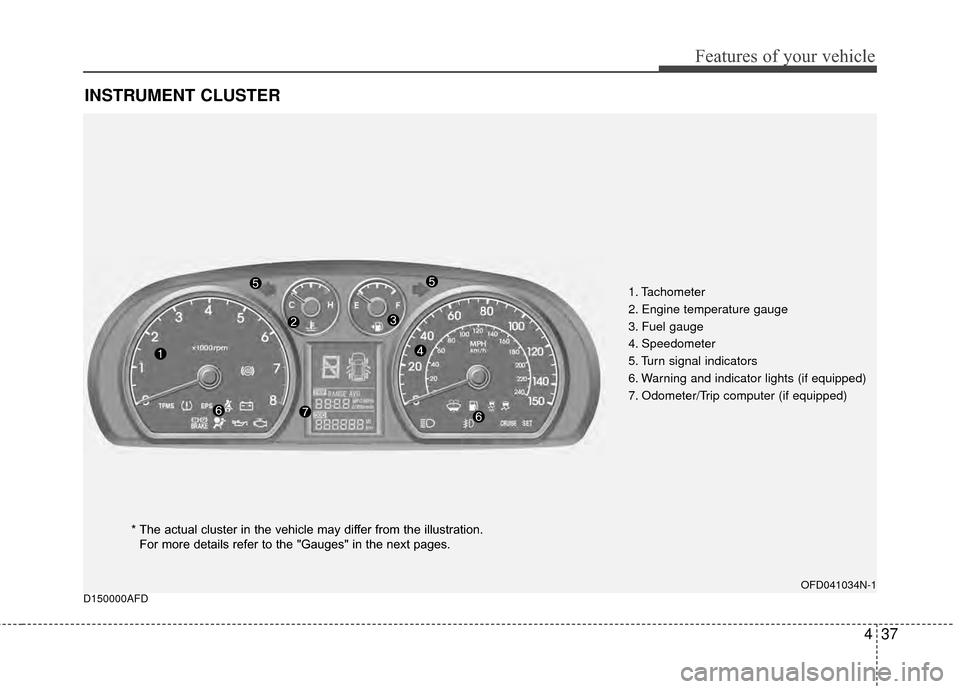
INSTRUMENT CLUSTER
1. Tachometer
2. Engine temperature gauge
3. Fuel gauge
4. Speedometer
5. Turn signal indicators
6. Warning and indicator lights (if equipped)
7. Odometer/Trip computer (if equipped)
OFD041034N-1
* The actual cluster in the vehicle may differ from the illustration.For more details refer to the "Gauges" in the next pages.
Page 121 of 402
445
Features of your vehicle
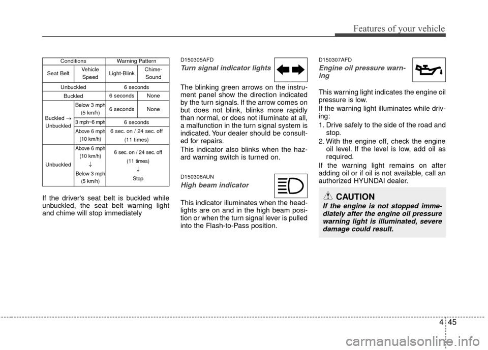
If the driver's seat belt is buckled while
unbuckled, the seat belt warning light
and chime will stop immediately
D150305AFD
Turn signal indicator lights
The blinking green arrows on the instru-
ment panel show the direction indicated
by the turn signals. If the arrow comes on
but does not blink, blinks more rapidly
than normal, or does not illuminate at all,
a malfunction in the turn signal system is
indicated. Your dealer should be consult-
ed for repairs.
This indicator also blinks when the haz-
ard warning switch is turned on.
D150306AUN
High beam indicator
This indicator illuminates when the head-
lights are on and in the high beam posi-
tion or when the turn signal lever is pulled
into the Flash-to-Pass position.
D150307AFD
Engine oil pressure warn-ing
This warning light indicates the engine oil
pressure is low.
If the warning light illuminates while driv-
ing:
1. Drive safely to the side of the road and stop.
2. With the engine off, check the engine oil level. If the level is low, add oil as
required.
If the warning light remains on after
adding oil or if oil is not available, call an
authorized HYUNDAI dealer.
CAUTION
If the engine is not stopped imme- diately after the engine oil pressurewarning light is illuminated, severe damage could result.
Conditions Warning Pattern
Unbuckled 6 seconds
Buckled
6 seconds
6 sec. on / 24 sec. off (11 times)
Seat Belt
Buckled →
Unbuckled
Unbuckled Vehicle
Speed
Below 3 mph (5 km/h)
3 mph~6 mph
Above 6 mph(10 km/h)
Above 6 mph (10 km/h)
↓
Below 3 mph (5 km/h) 6 sec. on / 24 sec. off
(11 times)↓
Stop
Light-Blink
6 seconds None
6 seconds None Chime-
Sound
Page 129 of 402
453
Features of your vehicle
D170400AFD
Self-diagnosis
If you don’t hear an audible warning
sound or if the buzzer sounds intermit-
tently when shifting the gear to the R
(Reverse) position, this may indicate a
malfunction in the rear parking assist sys-
tem. If this occurs, have your vehicle
checked by an authorized HYUNDAI
dealer as soon as possible.
D180000AUN
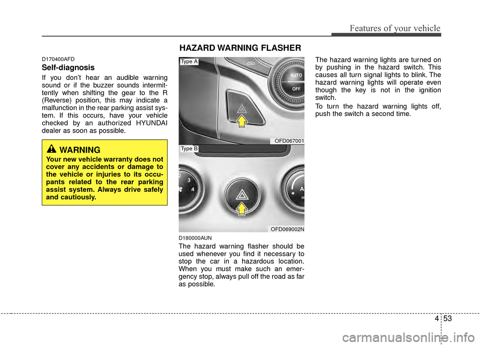
The hazard warning flasher should be
used whenever you find it necessary to
stop the car in a hazardous location.
When you must make such an emer-
gency stop, always pull off the road as far
as possible.The hazard warning lights are turned on
by pushing in the hazard switch. This
causes all turn signal lights to blink. The
hazard warning lights will operate even
though the key is not in the ignition
switch.
To turn the hazard warning lights off,
push the switch a second time.
WARNING
Your new vehicle warranty does not
cover any accidents or damage to
the vehicle or injuries to its occu-
pants related to the rear parking
assist system. Always drive safely
and cautiously.
HAZARD WARNING FLASHER
OFD067001
OFD069002N
Type B
Type A
Page 133 of 402
457
Features of your vehicle
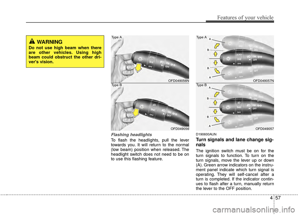
Flashing headlights
To flash the headlights, pull the lever
towards you. It will return to the normal
(low beam) position when released. The
headlight switch does not need to be on
to use this flashing feature.
D190600AUN
Turn signals and lane change sig-
nals
The ignition switch must be on for the
turn signals to function. To turn on the
turn signals, move the lever up or down
(A). Green arrow indicators on the instru-
ment panel indicate which turn signal is
operating. They will self-cancel after a
turn is completed. If the indicator contin-
ues to flash after a turn, manually return
the lever to the OFF position.
OFD049056N
OFD049056
Type A
Type BOFD049057N
OFD049057
Type A
Type B
WARNING
Do not use high beam when there
are other vehicles. Using high
beam could obstruct the other dri-
ver's vision.
Page 134 of 402
Features of your vehicle
58
4
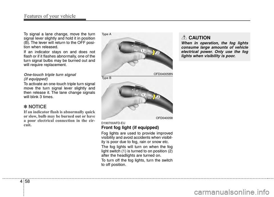
To signal a lane change, move the turn
signal lever slightly and hold it in position
(B). The lever will return to the OFF posi-
tion when released.
If an indicator stays on and does not
flash or if it flashes abnormally, one of the
turn signal bulbs may be burned out and
will require replacement.
One-touch triple turn signal
(if equipped)
To activate an one-touch triple turn signal
move the turn signal lever slightly and
then release it. The lane change signals
will blink 3 times.
✽ ✽ NOTICE
If an indicator flash is abnormally quick
or slow, bulb may be burned out or have
a poor electrical connection in the cir-
cuit.
D190700AFD-EU
Front fog light (if equipped)
Fog lights are used to provide improved
visibility and avoid accidents when visibil-
ity is poor due to fog, rain or snow etc.
The fog lights will turn on when the fog
light switch (1) is turned to on position (2)
after the headlights are turned on.
To turn off the fog lights, turn the switch
to off position.
CAUTION
When in operation, the fog lights
consume large amounts of vehicleelectrical power. Only use the fog lights when visibility is poor.
OFD040058N
OFD040058
Type A
Type B