seat control Hyundai Genesis 2012 User Guide
[x] Cancel search | Manufacturer: HYUNDAI, Model Year: 2012, Model line: Genesis, Model: Hyundai Genesis 2012Pages: 393, PDF Size: 8.81 MB
Page 62 of 393
Safety features of your vehicle
46 3
(Continued)
• Move your seat as far back as
practical from the front air bags,
while still maintaining control of
the vehicle.
• You and your passengers should
never sit or lean unnecessarily
close to the air bags. Improperly
positioned drivers and passen-
gers can be severely injured by
inflating air bags.
• Never lean against the door or
center console – always sit in an
upright position.
• No objects should be placed over
or near the air bag modules on
the steering wheel, instrument
panel, and the front passenger's
panel above the glove box,
because any such object could
cause harm if the vehicle is in a
crash severe enough to cause
the air bags to deploy.
• Do not tamper with or disconnect
SRS wiring or other components
of the SRS system. Doing so
could result in injury, due to acci-
dental deployment of the air bags
or by rendering the SRS inopera-
tive.
(Continued)(Continued)
• If the SRS air bag warning light
“ ”remains illuminated while
the vehicle is being driven, have
an authorized HYUNDAI dealer
inspect the air bag system as
soon as possible.
• Air bags can only be used once –
have an authorized HYUNDAI
dealer replace the air bag imme-
diately after deployment.
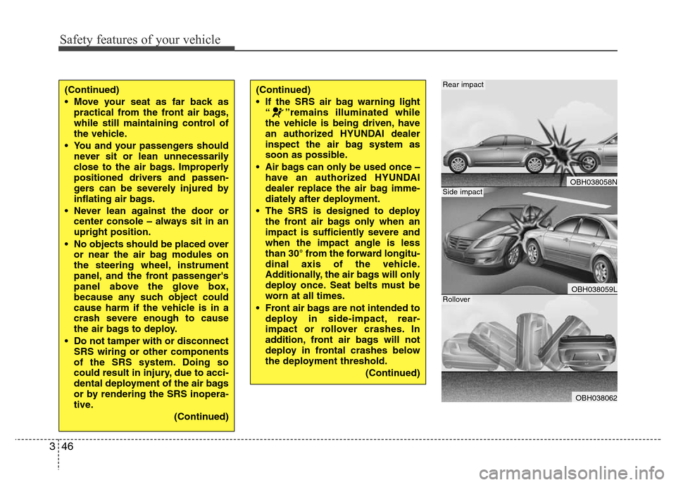
• The SRS is designed to deploy
the front air bags only when an
impact is sufficiently severe and
when the impact angle is less
than 30° from the forward longitu-
dinal axis of the vehicle.
Additionally, the air bags will only
deploy once. Seat belts must be
worn at all times.
• Front air bags are not intended to
deploy in side-impact, rear-
impact or rollover crashes. In
addition, front air bags will not
deploy in frontal crashes below
the deployment threshold.
(Continued)
OBH038058N
OBH038059L
OBH038062
Rear impact
Side impact
Rollover
Page 112 of 393
439
Features of your vehicle
D120000AEN
A driver position memory system is pro-
vided to store and recall the driver seat,
outside rearview mirror and steering
wheel positions with a simple button
operation. By saving the desired positions
into the system memory, different drivers
can reposition the driver seat, outside
rearview mirror and steering wheel based
upon their driving preference. If the bat-
tery is disconnected, the position memo-
ry will be lost and the driving positions
should be restored in the system.
✽NOTICE
The buzzer sounds 10 times if there is a
malfunction of the memory system.
Have the driver position memory system
checked by an authorized HYUNDAI
dealer.
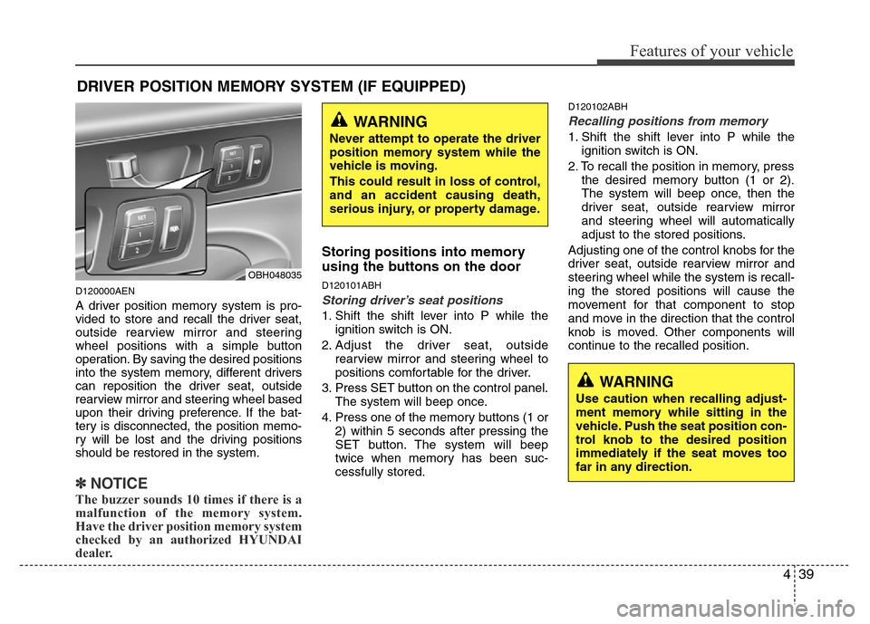
Storing positions into memory
using the buttons on the door
D120101ABH
Storing driver’s seat positions
1. Shift the shift lever into P while the
ignition switch is ON.
2. Adjust the driver seat, outside
rearview mirror and steering wheel to
positions comfortable for the driver.
3. Press SET button on the control panel.
The system will beep once.
4. Press one of the memory buttons (1 or
2) within 5 seconds after pressing the
SET button. The system will beep
twice when memory has been suc-
cessfully stored.
D120102ABH
Recalling positions from memory
1. Shift the shift lever into P while the
ignition switch is ON.
2. To recall the position in memory, press
the desired memory button (1 or 2).
The system will beep once, then the
driver seat, outside rearview mirror
and steering wheel will automatically
adjust to the stored positions.
Adjusting one of the control knobs for the
driver seat, outside rearview mirror and
steering wheel while the system is recall-
ing the stored positions will cause the
movement for that component to stop
and move in the direction that the control
knob is moved. Other components will
continue to the recalled position.
DRIVER POSITION MEMORY SYSTEM (IF EQUIPPED)
WARNING
Never attempt to operate the driver
position memory system while the
vehicle is moving.
This could result in loss of control,
and an accident causing death,
serious injury, or property damage.
WARNING
Use caution when recalling adjust-
ment memory while sitting in the
vehicle. Push the seat position con-
trol knob to the desired position
immediately if the seat moves too
far in any direction.
OBH048035
Page 118 of 393
445
Features of your vehicle
D140100AUN
Inside rearview mirror
Adjust the rearview mirror to center on
the view through the rear window. Make
this adjustment before you start driving.
D140102AUN
Electric chromic mirror (ECM)
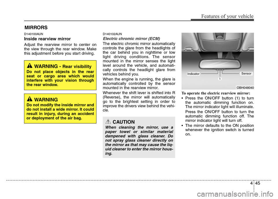
The electric chromic mirror automatically
controls the glare from the headlights of
the car behind you in nighttime or low
light driving conditions. The sensor
mounted in the mirror senses the light
level around the vehicle, and automati-
cally controls the headlight glare from
vehicles behind you.
When the engine is running, the glare is
automatically controlled by the sensor
mounted in the rearview mirror.
Whenever the shift lever is shifted into R
(Reverse), the mirror will automatically
go to the brightest setting in order to
improve the drivers view behind the vehi-
cle.To operate the electric rearview mirror:
• Press the ON/OFF button (1) to turn
the automatic dimming function on.
The mirror indicator light will illuminate.
Press the ON/OFF button to turn the
automatic dimming function off. The
mirror indicator light will turn off.
• The mirror defaults to the ON position
whenever the ignition switch is turned
on.
MIRRORS
CAUTION
When cleaning the mirror, use a
paper towel or similar material
dampened with glass cleaner. Do
not spray glass cleaner directly on
the mirror as that may cause the liq-
uid cleaner to enter the mirror hous-
ing.
OBH048040
IndicatorSensor
WARNING - Rear visibility
Do not place objects in the rear
seat or cargo area which would
interfere with your vision through
the rear window.
WARNING
Do not modify the inside mirror and
do not install a wide mirror. It could
result in injury, during an accident
or deployment of the air bag.
Page 225 of 393
53
Driving your vehicle
E020100AUN
Before entering vehicle
• Be sure that all windows, outside mir-
ror(s), and outside lights are clean.
• Check the condition of the tires.
• Check under the vehicle for any sign of
leaks.
• Be sure there are no obstacles behind
you if you intend to back up.
E020200AUN
Necessary inspections
Fluid levels, such as engine oil, engine
coolant, brake fluid, and washer fluid
should be checked on a regular basis,
with the exact interval depending on the
fluid. Further details are provided in sec-
tion 7, “Maintenance”.
E020300AUN
Before starting
• Close and lock all doors.
• Position the seat so that all controls are
easily reached.
• Adjust the inside and outside rearview
mirrors.
• Be sure that all lights work.
• Check all gauges.
• Check the operation of warning lights
when the ignition switch is turned to
the ON position.
• Release the parking brake and make
sure the brake warning light goes out.
For safe operation, be sure you are famil-
iar with your vehicle and its equipment.
BEFORE DRIVING
WARNING
All passengers must be properly
belted whenever the vehicle is mov-
ing. Refer to “Seat belts” in section
3 for more information on their
proper use.
WARNING
Always check the surrounding
areas near your vehicle for people,
especially children, before putting a
car into D (Drive) or R (Reverse).
WARNING
Driving while distracted can result
in a loss of vehicle control, that
may lead to an accident, severe
personal injury, and death. The dri-
ver’s primary responsibility is in
the safe and legal operation of a
vehicle, and use of any handheld
devices, other equipment, or vehi-
cle systems which take the driver’s
eyes, attention and focus away
from the safe operation of a vehicle
or which are not permissible by law
should never be used during oper-
ation of the vehicle.
Page 227 of 393
55
Driving your vehicle
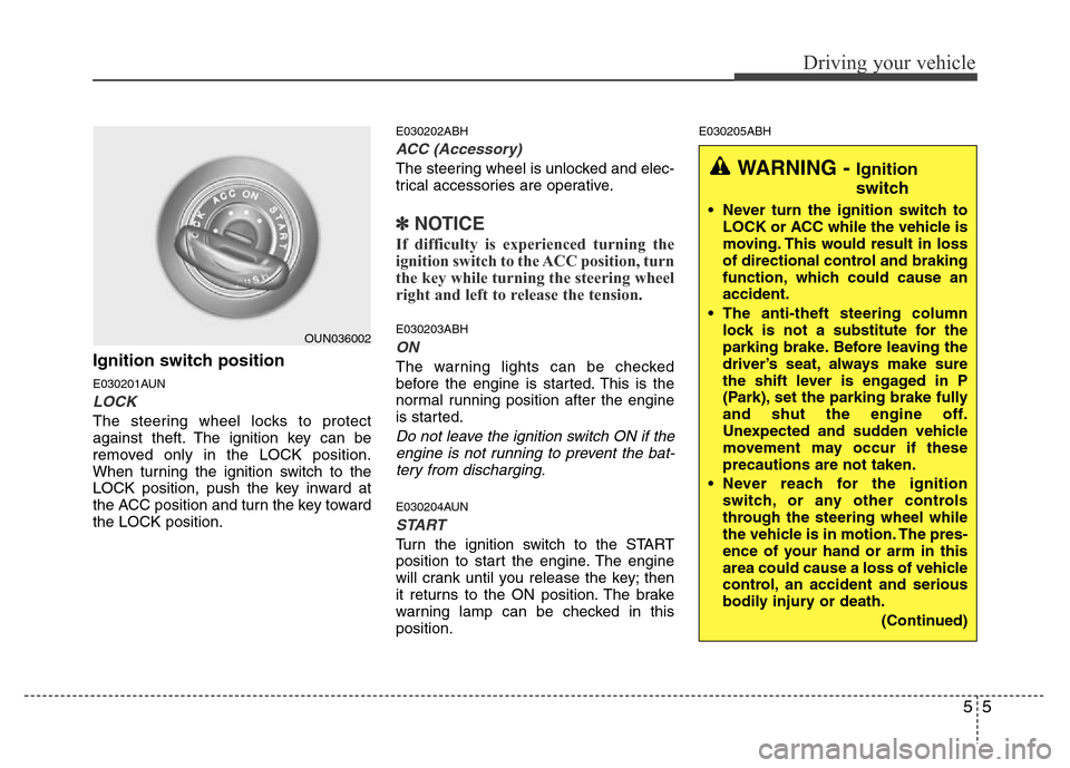
Ignition switch position
E030201AUN
LOCK
The steering wheel locks to protect
against theft. The ignition key can be
removed only in the LOCK position.
When turning the ignition switch to the
LOCK position, push the key inward at
the ACC position and turn the key toward
the LOCK position.
E030202ABH
ACC (Accessory)
The steering wheel is unlocked and elec-
trical accessories are operative.
✽NOTICE
If difficulty is experienced turning the
ignition switch to the ACC position, turn
the key while turning the steering wheel
right and left to release the tension.
E030203ABH
ON
The warning lights can be checked
before the engine is started. This is the
normal running position after the engine
is started.
Do not leave the ignition switch ON if the
engine is not running to prevent the bat-
tery from discharging.
E030204AUN
START
Turn the ignition switch to the START
position to start the engine. The engine
will crank until you release the key; then
it returns to the ON position. The brake
warning lamp can be checked in this
position.
E030205ABH
OUN036002
WARNING - Ignition
switch
• Never turn the ignition switch to
LOCK or ACC while the vehicle is
moving. This would result in loss
of directional control and braking
function, which could cause an
accident.
• The anti-theft steering column
lock is not a substitute for the
parking brake. Before leaving the
driver’s seat, always make sure
the shift lever is engaged in P
(Park), set the parking brake fully
and shut the engine off.
Unexpected and sudden vehicle
movement may occur if these
precautions are not taken.
• Never reach for the ignition
switch, or any other controls
through the steering wheel while
the vehicle is in motion. The pres-
ence of your hand or arm in this
area could cause a loss of vehicle
control, an accident and serious
bodily injury or death.
(Continued)
Page 234 of 393
Driving your vehicle
12 5
For smooth operation, depress the brake
pedal when shifting from N (Neutral) to a
forward or reverse gear.E060101BBH
Transmission ranges
The indicator in the instrument cluster
displays the shift lever position when the
ignition switch is in the ON position.
P (Park)
Always come to a complete stop before
shifting into P (Park). This position locks
the transmission and prevents the drive
wheels from rotating.
WARNING- Automatic
transmission
• Always check the surrounding
areas near your vehicle for peo-
ple, especially children, before
shifting a car into D (Drive) or R
(Reverse).
• Before leaving the driver’s seat,
always make sure the shift lever
is in the P (Park) position; then
set the parking brake fully and
shut the engine off. Unexpected
and sudden vehicle movement
can occur if these precautions
are not followed in the order iden-
tified.
CAUTION
• To avoid damage to your trans-
mission, do not accelerate the
engine in R (Reverse) or any for-
ward gear position with the
brakes on.
• When stopped on an incline, do
not hold the vehicle stationary
with engine power. Use the serv-
ice brake or the parking brake.
• Do not shift from N (Neutral) or P
(Park) into D (Drive), or R
(Reverse) when the engine is
above idle speed.
WARNING
• Shifting into P (Park) while the
vehicle is in motion will cause the
drive wheels to lock which will
cause you to lose control of the
vehicle.
• Do not use the P (Park) position
in place of the parking brake.
Always make sure the shift lever
is latched in the P (Park) position
and set the parking brake fully.
• Never leave a child unattended in
a vehicle.
Page 249 of 393
527
Driving your vehicle
- the hood is open with transmission
in D (Drive).
- the trunk lid is open with transmis-
sion in R (Reverse).
- the driver's seat belt is unbuckled
and the driver's door is open.
- AUTO HOLD is operating for a long
period of time.
- the vehicle is standing on a steep
slope.
In these cases, the brake warning light
comes on, the AUTO HOLD indicator
changes from green to white, and a
warning sounds and a message will
appear to inform you that EPB has
been automatically engaged.
Before driving off again, press foot
brake pedal, check the surrounding
area near your vehicle and release
parking brake manually with the EPB
switch.
• When AUTO HOLD is ON and the
vehicle comes to a stop on a steep
slope (about 25% gradient or more),
the EPB will be automatically
engaged. In this case, when you
release EPB manually by pressing the
EPB switch with foot brake pedal
pressed, AUTO HOLD will hold the
vehicle for 3 seconds in order to pre-
vent the vehicle from rolling back
during the launch.• If the AUTO HOLD malfunction indi-
cator lights up yellow on the LCD
screen, the AUTO HOLD is not work-
ing properly. Take your vehicle to an
authorized HYUNDAI dealer and
have the system checked.
• While operating Auto Hold, you may
hear mechanical noise. However, it is
normal operating noise.E070300AEN-EE
Anti-lock brake system (ABS)
WARNING
ABS (or ESP) will not prevent acci-
dents due to improper or danger-
ous driving maneuvers. Even
though vehicle control is improved
during emergency braking, always
maintain a safe distance between
you and objects ahead. Vehicle
speeds should always be reduced
during extreme road conditions.
The braking distance for cars
equipped with an anti-lock braking
system (or Electronic Stability
Program system) may be longer
than for those without it in the fol-
lowing road conditions.
During these conditions the vehicle
should be driven at reduced
speeds:
• Rough, gravel or snow-covered
roads.
• With tire chains installed.
(Continued)
WARNING
• Press the accelerator pedal slow-
ly when you start the vehicle.
• For your safety, cancel the AUTO
HOLD when you drive downhill or
back up the vehicle or park the
vehicle.
CAUTION
If there is a malfunction with the dri-
ver’s door, hood or trunk open
detection system, the AUTO HOLD
may not work properly.
Take your vehicle to an authorized
HYUNDAI dealer and have the sys-
tem checked.
Page 309 of 393
617
What to do in an emergency
10. Loosen the wheel nuts and
remove them with your fingers.
Slide the wheel off the studs and
lay it flat so it cannot roll away. To
put the wheel on the hub, pick up
the spare tire, line up the holes
with the studs and slide the
wheel onto them. If this is diffi-
cult, tip the wheel slightly and get
the top hole in the wheel lined up
with the top stud. Then jiggle the
wheel back and forth until the
wheel can be slid over the other
studs.11. To reinstall the wheel, hold it on
the studs, put the wheel nuts on
the studs and tighten them finger
tight. The nuts should be installed
with their tapered small diameter
ends directed inward. Jiggle the
tire to be sure it is completely
seated, then tighten the nuts as
much as possible with your fin-
gers again.
12. Lower the car to the ground by
turning the wheel nut wrench
counterclockwise.
WARNING
Wheels may have sharp edges.
Handle them carefully to avoid
possible severe injury. Before
putting the wheel into place, be
sure that there is nothing on the
hub or wheel (such as mud, tar,
gravel, etc.) that interferes with
the wheel from fitting solidly
against the hub.
If there is, remove it. If there is
not good contact on the mount-
ing surface between the wheel
and hub, the wheel nuts could
come loose and cause the loss
of a wheel. Loss of a wheel may
result in loss of control of the
vehicle. This may cause serious
injury or death.
Page 366 of 393
Maintenance
48 7
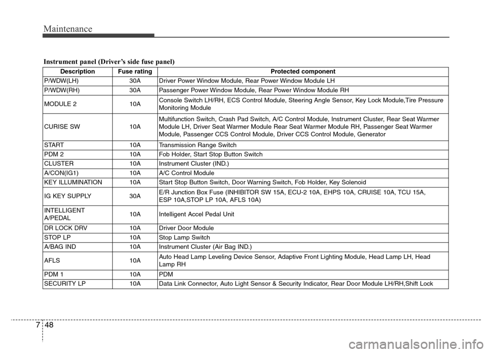
Instrument panel (Driver’s side fuse panel)
Description Fuse rating Protected component
P/WDW(LH) 30A Driver Power Window Module, Rear Power Window Module LH
P/WDW(RH) 30A Passenger Power Window Module, Rear Power Window Module RH
MODULE 2 10AConsole Switch LH/RH, ECS Control Module, Steering Angle Sensor, Key Lock Module,Tire Pressure
Monitoring Module
CURISE SW 10AMultifunction Switch, Crash Pad Switch, A/C Control Module, Instrument Cluster, Rear Seat Warmer
Module LH, Driver Seat Warmer Module Rear Seat Warmer Module RH, Passenger Seat Warmer
Module, Passenger CCS Control Module, Driver CCS Control Module, Generator
START 10A Transmission Range Switch
PDM 2 10A Fob Holder, Start Stop Button Switch
CLUSTER 10A Instrument Cluster (IND.)
A/CON(IG1) 10A A/C Control Module
KEY ILLUMINATION 10A Start Stop Button Switch, Door Warning Switch, Fob Holder, Key Solenoid
IG KEY SUPPLY 30AE/R Junction Box Fuse (INHIBITOR SW 15A, ECU-2 10A, EHPS 10A, CRUISE 10A, TCU 15A,
ESP 10A,STOP LP 10A, AFLS 10A)
INTELLIGENT
A/PEDAL10A Intelligent Accel Pedal Unit
DR LOCK DRV 10A Driver Door Module
STOP LP 10A Stop Lamp Switch
A/BAG IND 10A Instrument Cluster (Air Bag IND.)
AFLS 10AAuto Head Lamp Leveling Device Sensor, Adaptive Front Lighting Module, Head Lamp LH, Head
Lamp RH
PDM 1 10A PDM
SECURITY LP 10A Data Link Connector, Auto Light Sensor & Security Indicator, Rear Door Module LH/RH,Shift Lock
Page 367 of 393
749
Maintenance
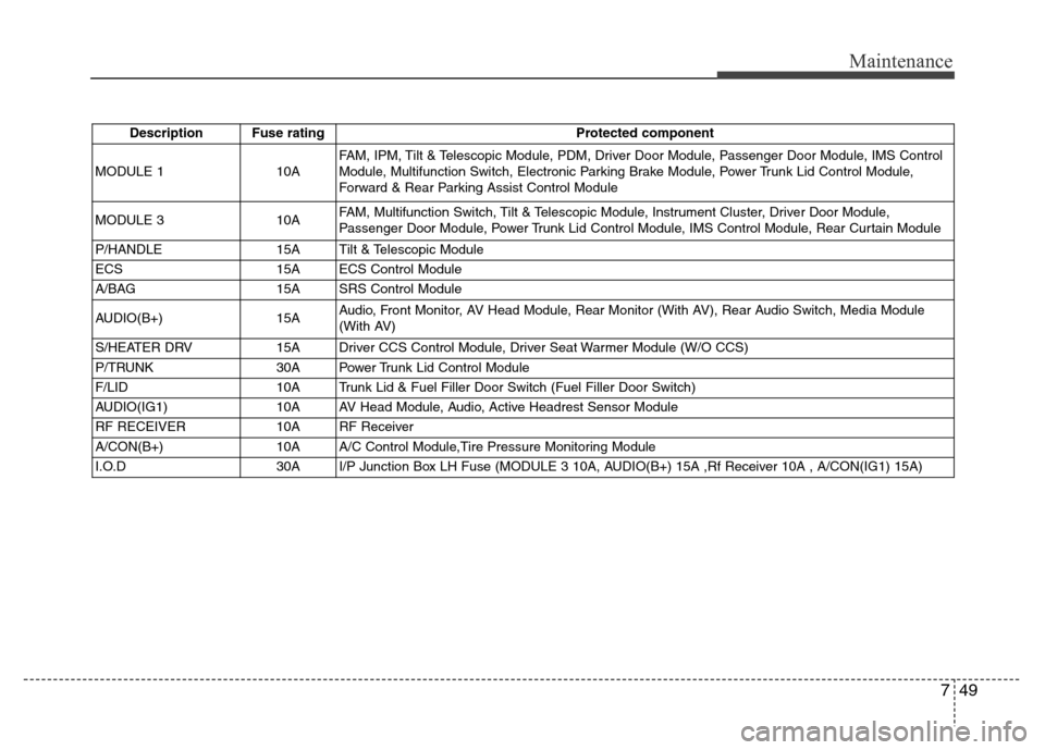
Description Fuse rating Protected component
MODULE 110AFAM, IPM, Tilt & Telescopic Module, PDM, Driver Door Module, Passenger Door Module, IMS Control
Module, Multifunction Switch, Electronic Parking Brake Module, Power Trunk Lid Control Module,
Forward & Rear Parking Assist Control Module
MODULE 3 10AFAM, Multifunction Switch, Tilt & Telescopic Module, Instrument Cluster, Driver Door Module,
Passenger Door Module, Power Trunk Lid Control Module, IMS Control Module, Rear Curtain Module
P/HANDLE 15A Tilt & Telescopic Module
ECS 15A ECS Control Module
A/BAG 15A SRS Control Module
AUDIO(B+) 15AAudio, Front Monitor, AV Head Module, Rear Monitor (With AV), Rear Audio Switch, Media Module
(With AV)
S/HEATER DRV 15A Driver CCS Control Module, Driver Seat Warmer Module (W/O CCS)
P/TRUNK 30A Power Trunk Lid Control Module
F/LID 10A Trunk Lid & Fuel Filler Door Switch (Fuel Filler Door Switch)
AUDIO(IG1) 10A AV Head Module, Audio, Active Headrest Sensor Module
RF RECEIVER 10A RF Receiver
A/CON(B+) 10A A/C Control Module,Tire Pressure Monitoring Module
I.O.D 30A I/P Junction Box LH Fuse (MODULE 3 10A, AUDIO(B+) 15A ,Rf Receiver 10A , A/CON(IG1) 15A)