fuel cap Hyundai Genesis Coupe 2011 Owner's Manual
[x] Cancel search | Manufacturer: HYUNDAI, Model Year: 2011, Model line: Genesis Coupe, Model: Hyundai Genesis Coupe 2011Pages: 343, PDF Size: 34.28 MB
Page 10 of 343
13
Introduction
A020103AUN
Gasoline containing alcohol andmethanol
Gasohol, a mixture of gasoline and
ethanol (also known as grain alcohol),and gasoline or gasohol containing
methanol (also known as wood alcohol)
are being marketed along with or instead
of leaded gasoline. Do not use gasohol containing more than 10% ethanol, and do not use gasoline or
gasohol containing any methanol. Either
of these fuels may cause drivability prob-lems and damage to the fuel system.
Discontinue using gasohol of any kind if
drivability problems occur.
Vehicle damage or drivability problems
may not be covered by the manufactur-
er’s warranty if they result from the useof:
1. Gasohol containing more than 10% ethanol.
2. Gasoline or gasohol containing methanol.
3. Leaded fuel or leaded gasohol. A020104AEN
Use of MTBE
HYUNDAI recommends avoiding fuels
containing MTBE (Methyl Tertiary Butyl
Ether) over 15.0% vol. (Oxygen Content
2.7% weight) in your vehicle.
Fuel containing MTBE over 15.0% vol.
(Oxygen Content 2.7% weight) may
reduce vehicle performance and produce
vapor lock or hard starting.
WARNING
• Do not "top off" after the nozzle automatically shuts off when refueling.
Always check that the fuel cap is installed securely to prevent fuel
spillage in the event of an acci-dent.
CAUTION
NEVER USE LEADED FUEL. The
use of leaded fuel is detrimental to
the catalytic converter and willdamage the engine control sys-tem’s oxygen sensor and affect emission control.
Never add any fuel system cleaningagents to the fuel tank other thanwhat has been specified. (Consultan authorized HYUNDAI dealer for
details.)
CAUTION
Your New Vehicle Limited Warrantymay not cover damage to the fuel
system and any performance prob-lems that are caused by the use of fuels containing methanol or fuelscontaining MTBE (Methyl Tertiary
Butyl Ether) over 15.0% vol.(Oxygen Content 2.7% weight.)
CAUTION
Never use gasohol which contains methanol. Discontinue use of any
gasohol product which impairs dri-vability.
Page 93 of 343
425
Features of your vehicle
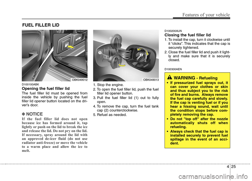
D100100ABK Opening the fuel filler lid
The fuel filler lid must be opened from
inside the vehicle by pushing the fuel
filler lid opener button located on the dri-
ver’s door.
✽✽NOTICE
If the fuel filler lid does not open
because ice has formed around it, tap
lightly or push on the lid to break the ice
and release the lid. Do not pry on the lid.
If necessary, spray around the lid with
an approved de-icer fluid (do not use
radiator anti-freeze) or move the vehicle
to a warm place and allow the ice to
melt.
1. Stop the engine.
2. To open the fuel filler lid, push the fuel filler lid opener button.
3. Pull the fuel filler lid (1) out to fully open.
4. To remove the cap, turn the fuel tank cap (2) counterclockwise.
5. Refuel as needed. D100200AUN Closing the fuel filler lid
1. To install the cap, turn it clockwise until
it “clicks”. This indicates that the cap is securely tightened.
2. Close the fuel filler lid and push it light- ly and make sure that it is securelyclosed.
D100300AEN
FUEL FILLER LID
OBK049012OBK049013WARNING
- Refueling
If pressurized fuel sprays out, it can cover your clothes or skin
and thus subject you to the risk
of fire and burns. Always remove
the fuel cap carefully and slowly.
If the cap is venting fuel or if you
hear a hissing sound, wait until
the condition stops before com-
pletely removing the cap.
Do not "top off" after the nozzle automatically shuts off whenrefueling.
Always check that the fuel cap is installed securely to prevent fuel
spillage in the event of an acci-dent.
Page 94 of 343
Features of your vehicle
26
4
(Continued)
Do not get back into a vehicle
once you have begun refueling
since you can generate static
electricity by touching, rubbing
or sliding against any item or fab-
ric (polyester, satin, nylon, etc.)
capable of producing static elec-
tricity. Static electricity discharge
can ignite fuel vapors resulting in
rapid burning. If you must re-
enter the vehicle, you should
once again eliminate potentially
dangerous static electricity dis-
charge by touching a metal part
of the vehicle, away from the fuel
filler neck, nozzle or other gaso-
line source.
When using an approved portable fuel container, be sure toplace the container on the
ground prior to refueling. Static
electricity discharge from the
container can ignite fuel vapors
causing a fire. Once refueling has
begun, contact with the vehicleshould be maintained until the
filling is complete.
(Continued)WARNING - Refueling dan-
gers
Automotive fuels are flammable
materials. When refueling, please
note the following guidelines care-
fully. Failure to follow these guide-
lines may result in severe personal
injury, severe burns or death by fire
or explosion.
Read and follow all warnings at the gas station facility.
Before refueling note the location of the Emergency Gasoline Shut-
Off, if available, at the gas station
facility.
Before touching the fuel nozzle, you should eliminate potentially
dangerous static electricity dis-
charge by touching another metal
part of the vehicle, a safe dis-
tance away from the fuel filler
neck, nozzle, or other gas source.
(Continued)(Continued)Use only approved portable plas-
tic fuel containers designed to
carry and store gasoline.
Do not use cellular phones while refueling. Electric current and/or
electronic interference from cel-
lular phones can potentially
ignite fuel vapors causing a fire.
When refueling, always shut the engine off. Sparks produced byelectrical components related to
the engine can ignite fuel vapors
causing a fire. Once refueling is
complete, check to make sure thefiller cap and filler door are
securely closed, before starting
the engine.
DO NOT use matches or a lighter and DO NOT SMOKE or leave a lit
cigarette in your vehicle while at
a gas station especially during
refueling. Automotive fuel is
highly flammable and can, when
ignited, result in fire.
(Continued)
Page 95 of 343
427
Features of your vehicle
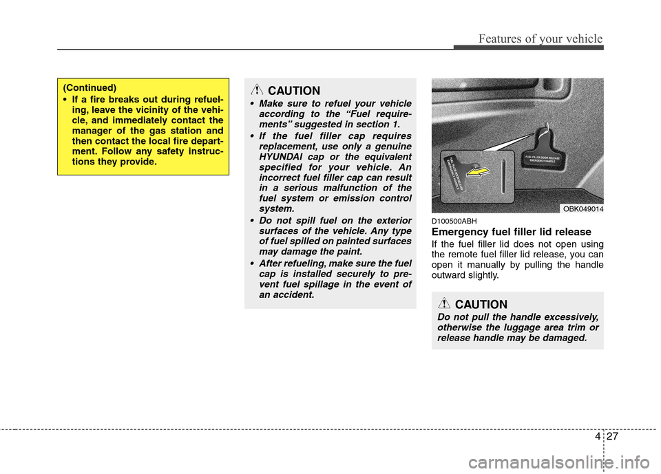
D100500ABH
Emergency fuel filler lid release If the fuel filler lid does not open using
the remote fuel filler lid release, you can
open it manually by pulling the handle
outward slightly.
(Continued)
If a fire breaks out during refuel-ing, leave the vicinity of the vehi-
cle, and immediately contact the
manager of the gas station and
then contact the local fire depart-
ment. Follow any safety instruc-
tions they provide.CAUTION
Make sure to refuel your vehicle
according to the “Fuel require-
ments” suggested in section 1.
If the fuel filler cap requires replacement, use only a genuineHYUNDAI cap or the equivalent
specified for your vehicle. An incorrect fuel filler cap can resultin a serious malfunction of thefuel system or emission control
system.
Do not spill fuel on the exterior surfaces of the vehicle. Any typeof fuel spilled on painted surfacesmay damage the paint.
After refueling, make sure the fuel cap is installed securely to pre-vent fuel spillage in the event ofan accident.
CAUTION
Do not pull the handle excessively,
otherwise the luggage area trim or release handle may be damaged.
OBK049014
Page 109 of 343
441
Features of your vehicle
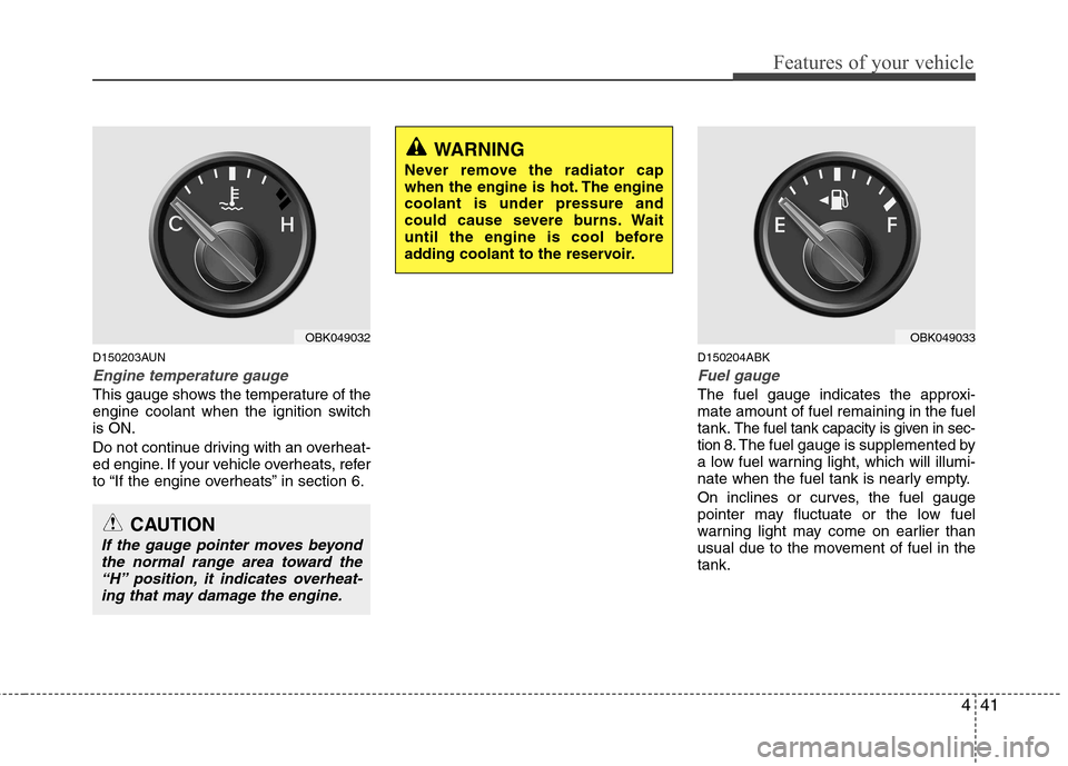
D150203AUN
Engine temperature gauge
This gauge shows the temperature of the
engine coolant when the ignition switchis ON.
Do not continue driving with an overheat-
ed engine. If your vehicle overheats, refer
to “If the engine overheats” in section 6.D150204ABK
Fuel gauge
The fuel gauge indicates the approxi- mate amount of fuel remaining in the fueltank.
The fuel tank capacity is given in sec-
tion 8.The fuel gauge is supplemented by
a low fuel warning light, which will illumi-
nate when the fuel tank is nearly empty.
On inclines or curves, the fuel gauge
pointer may fluctuate or the low fuel
warning light may come on earlier than
usual due to the movement of fuel in thetank.
OBK049032
CAUTION
If the gauge pointer moves beyond
the normal range area toward the“H” position, it indicates overheat-
ing that may damage the engine.
WARNING
Never remove the radiator cap
when the engine is hot. The enginecoolant is under pressure and
could cause severe burns. Wait
until the engine is cool before
adding coolant to the reservoir.
OBK049033
Page 239 of 343
Driving your vehicle
46
5
E160000ABH
This section will guide you in the proper
loading of your vehicle, to keep your
loaded vehicle weight within its design
rating capability. Properly loading your
vehicle will provide maximum return of
the vehicle design performance. Before
loading your vehicle, familiarize yourself
with the following terms for determining
your vehicle's weight ratings, from the
vehicle's specifications and the certifica-tion label:
E160100AUN Base curb weight
This is the weight of the vehicle including a full tank of fuel and all standard equip-
ment. It does not include passengers,
cargo, or optional equipment.
E160200AUN
Vehicle curb weight
This is the weight of your new vehicle
when you picked it up from your dealer
plus any aftermarket equipment.
E160300AUN
Cargo weight
This figure includes all weight added to
the Base Curb Weight, including cargoand optional equipment. E160400AUN
GAW (Gross axle weight)
This is the total weight placed on each
axle (front and rear) - including vehicle
curb weight and all payload.
E160500AUN
GAWR (Gross axle weight rating)
This is the maximum allowable weight
that can be carried by a single axle (front
or rear). These numbers are shown on
the certification label.
The total load on each axle must never
exceed its GAWR.
E160600AUN
GVW (Gross vehicle weight)
This is the Base Curb Weight plus actual
Cargo Weight plus passengers.
E160700AUN
GVWR (Gross vehicle weight rating)
This is the maximum allowable weight of
the fully loaded vehicle (including all
options, equipment, passengers and
cargo). The GVWR is shown on the cer-
tification label located on the driver’s (or
front passenger’s) door sill.
E160800AUN Overloading
VEHICLE WEIGHT
WARNING -
Vehicle weight
The gross axle weight rating
(GAWR) and the gross vehicle
weight rating (GVWR) for your vehi-
cle are on the certification label
attached to the driver's (or front
passenger’s) door. Exceedingthese ratings can cause an acci-
dent or vehicle damage. You can
calculate the weight of your load byweighing the items (and people)
before putting them in the vehicle.
Be careful not to overload your
vehicle.
Page 268 of 343
79
Maintenance
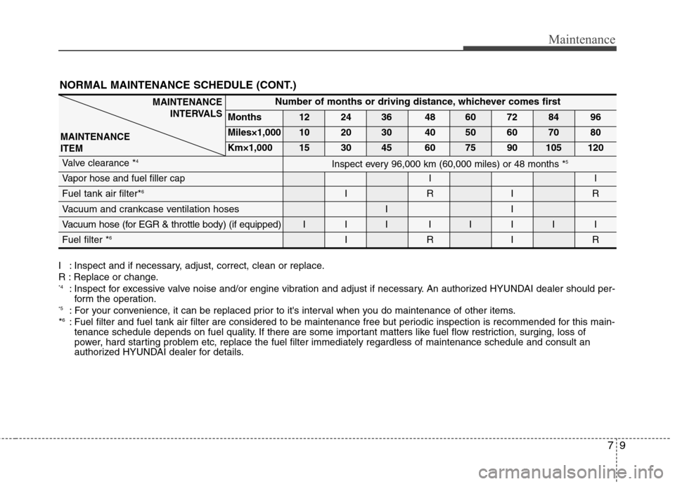
NORMAL MAINTENANCE SCHEDULE (CONT.)
MAINTENANCEINTERVALS
MAINTENANCE ITEMNumber of months or driving distance, whichever comes first
Months 12 24 36 48 60 72 84 96
Miles×1,000 10 20 30 40 50 60 70 80
Km×1,000 15 30 45 60 75 90 105 120
Valve clearance * 4
Vapor hose and fuel filler cap
II
Fuel tank air filter*6
IRIR
Vacuum and crankcase ventilation hoses I I
Vacuum hose (for EGR & throttle body) (if equipped) I I I I I I I IFuel filter * 6
IRIR
Inspect every 96,000 km (60,000 miles) or 48 months * 5
I : Inspect and if necessary, adjust, correct, clean or replace.
R : Replace or change. *4
: Inspect for excessive valve noise and/or engine vibration and adjust if necessary. An authorized HYUNDAI dealer should per-
form the operation.
*5 : For your convenience, it can be replaced prior to it's interval when you do maintenance of other items.
* 6
: Fuel filter and fuel tank air filter are considered to be maintenance free but periodic inspection is recommended for this mai n-
tenance schedule depends on fuel quality. If there are some important matters like fuel flow restriction, surging, loss of
power, hard starting problem etc, replace the fuel filter immediately regardless of maintenance schedule and consult an
authorized HYUNDAI dealer for details.
Page 274 of 343
715
Maintenance
G050600AUN
Vapor hose and fuel filler cap
The vapor hose and fuel filler cap should
be inspected at those intervals specified
in the maintenance schedule. Make sure
that a new vapor hose or fuel filler cap iscorrectly replaced.
G050700AUN
Vacuum crankcase ventilation hoses (if equipped)
Inspect the surface of hoses for evidence
of heat and/or mechanical damage. Hard
and brittle rubber, cracking, tears, cuts,
abrasions, and excessive swelling indi-
cate deterioration. Particular attention
should be paid to examine those hose
surfaces nearest to high heat sources,
such as the exhaust manifold. Inspect the hose routing to assure that the hoses do not come in contact with
any heat source, sharp edges or movingcomponent which might cause heat dam-
age or mechanical wear. Inspect all hose
connections, such as clamps and cou-
plings, to make sure they are secure, and
that no leaks are present. Hoses should
be replaced immediately if there is any
evidence of deterioration or damage.G050800AEN
Air cleaner filter
A Genuine HYUNDAI air cleaner filter is recommended when the filter isreplaced.
G050900AUN Spark plugs
Make sure to install new spark plugs of
the correct heat range. G051000AEN
Valve clearance
Inspect excessive valve noise and/or
engine vibration and adjust if necessary.
An authorized HYUNDAI dealer should
perform the operation.
G051100AUN Cooling system
Check cooling system components, such
as radiator, coolant reservoir, hoses and
connections for leakage and damage.
Replace any damaged parts.
G051200AUN Coolant The coolant should be changed at the
intervals specified in the maintenance
schedule. G051300ABK
Manual transmission fluid (if equipped)
Inspect the manual transmission fluid
according to the maintenance schedule. G051400ABK
Automatic transmission fluid (if equipped)
Inspect the automatic transmission fluid
according to the maintenance schedule.
G051500AUN Brake hoses and lines
Visually check for proper installation,
chafing, cracks, deterioration and any
leakage. Replace any deteriorated or
damaged parts immediately.
Page 325 of 343
Maintenance
66
7
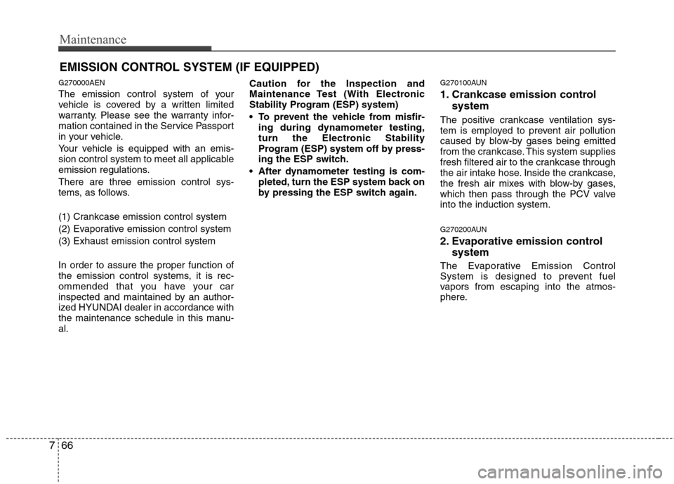
EMISSION CONTROL SYSTEM (IF EQUIPPED)
G270000AEN
The emission control system of your
vehicle is covered by a written limited
warranty. Please see the warranty infor-
mation contained in the Service Passport
in your vehicle.
Your vehicle is equipped with an emis-
sion control system to meet all applicable
emission regulations. There are three emission control sys-
tems, as follows.
(1) Crankcase emission control system
(2) Evaporative emission control system(3) Exhaust emission control system In order to assure the proper function of
the emission control systems, it is rec-
ommended that you have your car
inspected and maintained by an author-
ized HYUNDAI dealer in accordance with
the maintenance schedule in this manu-al. Caution for the Inspection and
Maintenance Test (With Electronic
Stability Program (ESP) system)
To prevent the vehicle from misfir-
ing during dynamometer testing,
turn the Electronic Stability
Program (ESP) system off by press-
ing the ESP switch.
After dynamometer testing is com- pleted, turn the ESP system back on
by pressing the ESP switch again. G270100AUN
1. Crankcase emission control
system
The positive crankcase ventilation sys-
tem is employed to prevent air pollution
caused by blow-by gases being emitted
from the crankcase. This system supplies
fresh filtered air to the crankcase through
the air intake hose. Inside the crankcase,
the fresh air mixes with blow-by gases,
which then pass through the PCV valveinto the induction system.
G270200AUN
2. Evaporative emission control system
The Evaporative Emission Control
System is designed to prevent fuel
vapors from escaping into the atmos-
phere.
Page 331 of 343
Specifications & Consumer information
4
8
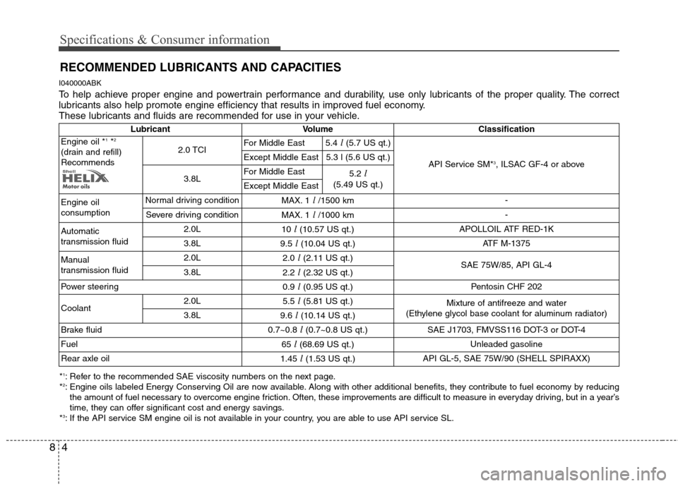
RECOMMENDED LUBRICANTS AND CAPACITIES
I040000ABK
To help achieve proper engine and powertrain performance and durability, use only lubricants of the proper quality. The correct
lubricants also help promote engine efficiency that results in improved fuel economy.
These lubricants and fluids are recommended for use in your vehicle.
* 1
: Refer to the recommended SAE viscosity numbers on the next page.
* 2
: Engine oils labeled Energy Conserving Oil are now available. Along with other additional benefits, they contribute to fuel economy by reducing
the amount of fuel necessary to overcome engine friction. Often, these improvements are difficult to measure in everyday driving, but in a year’s
time, they can offer significant cost and energy savings.
* 3
: If the API service SM engine oil is not available in your country, you are able to use API service SL. Lubricant Volume
Classification
Engine oil * 1
*2
(drain and refill)Recommends 2.0 TCI
For Middle East
5.4l (5.7 US qt.)
API Service SM*3
, ILSAC GF-4 or above
Except Middle East 5.3 l (5.6 US qt.)
3.8L For Middle East
5.2l
(5.49 US qt.)
Except Middle East
Engine oil consumption Normal driving condition
MAX. 1l /1500 km -
Severe driving condition MAX. 1l /1000 km -
Automatic
transmission fluid 2.0L
10l (10.57 US qt.) APOLLOIL ATF RED-1K
3.8L 9.5l (10.04 US qt.) ATF M-1375
Manual
transmission fluid 2.0L
2.0l (2.11 US qt.)
SAE 75W/85, API GL-4
3.8L 2.2l (2.32 US qt.)
Power steering 0.9l (0.95 US qt.) Pentosin CHF 202
Coolant 2.0L
5.5l (5.81 US qt.)
Mixture of antifreeze and water
(Ethylene glycol base coolant for aluminum radiator)
3.8L 9.6l (10.14 US qt.)
Brake fluid 0.7~0.8l (0.7~0.8 US qt.) SAE J1703, FMVSS116 DOT-3 or DOT-4
Fuel 65l (68.69 US qt.) Unleaded gasoline
Rear axle oil 1.45l (1.53 US qt.) API GL-5, SAE 75W/90 (SHELL SPIRAXX)