sensor HYUNDAI GENESIS G80 2009 User Guide
[x] Cancel search | Manufacturer: HYUNDAI, Model Year: 2009, Model line: GENESIS G80, Model: HYUNDAI GENESIS G80 2009Pages: 332, PDF Size: 20.46 MB
Page 94 of 332
433
Features of your vehicle
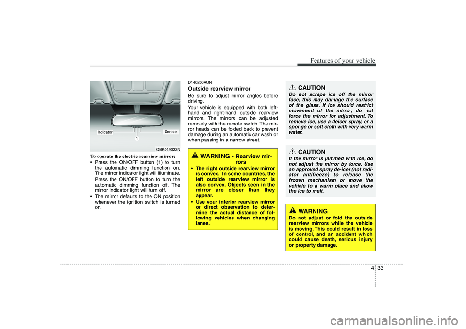
To operate the electric rearview mirror:
Press the ON/OFF button (1) to turnthe automatic dimming function on.
The mirror indicator light will illuminate.
Press the ON/OFF button to turn the
automatic dimming function off. The
mirror indicator light will turn off.
The mirror defaults to the ON position whenever the ignition switch is turnedon. D140200AUN
Outside rearview mirror
Be sure to adjust mirror angles before
driving.
Your vehicle is equipped with both left-
hand and right-hand outside rearview
mirrors. The mirrors can be adjusted
remotely with the remote switch. The mir-
ror heads can be folded back to prevent
damage during an automatic car wash or
when passing in a narrow street.
CAUTION
Do not scrape ice off the mirror
face; this may damage the surface of the glass. If ice should restrict movement of the mirror, do not
force the mirror for adjustment. To remove ice, use a deicer spray, or asponge or soft cloth with very warm water.
CAUTION
If the mirror is jammed with ice, donot adjust the mirror by force. Usean approved spray de-icer (not radi- ator antifreeze) to release the
frozen mechanism or move the vehicle to a warm place and allow the ice to melt.
WARNING
Do not adjust or fold the outside
rearview mirrors while the vehicle
is moving. This could result in loss
of control, and an accident which
could cause death, serious injury
or property damage.
WARNING - Rearview mir-
rors
The right outside rearview mirror is convex. In some countries, the
left outside rearview mirror is
also convex. Objects seen in the
mirror are closer than they
appear.
Use your interior rearview mirror or direct observation to deter-
mine the actual distance of fol-
lowing vehicles when changinglanes.
OBK049022N
IndicatorSensor
Page 114 of 332
453
Features of your vehicle
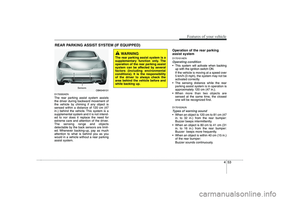
D170000AEN
The rear parking assist system assists
the driver during backward movement of
the vehicle by chiming if any object issensed within a distance of 120 cm (47
in.) behind the vehicle. This system is asupplemental system and it is not intend-
ed to nor does it replace the need for
extreme care and attention of the driver.
The sensing range and objects
detectable by the back sensors are limit-
ed. Whenever backing-up, pay as much
attention to what is behind you as you
would in a vehicle without a rear parkingassist system.Operation of the rear parking assist system D170101AEN
Operating condition
This system will activate when backing
up with the ignition switch ON.
If the vehicle is moving at a speed over
5 km/h (3 mph), the system may not be
activated correctly.
The sensing distance while the rear parking assist system is in operation is
approximately 120 cm (47 in.).
When more than two objects are sensed at the same time, the closest
one will be recognized first.
D170102AUN
Types of warning sound
When an object is 120 cm to 81 cm (47 in. to 32 in.) from the rear bumper:
Buzzer beeps intermittently.
When an object is 80 cm to 41 cm (31 in. to 16 in.) from the rear bumper:
Buzzer beeps more frequently.
When an object is within 40 cm (15 in.) of the rear bumper:
Buzzer sounds continuously.
REAR PARKING ASSIST SYSTEM (IF EQUIPPED)
OBK049131
WARNING
The rear parking assist system is a
supplementary function only. Theoperation of the rear parking assist
system can be affected by several
factors (including environmental
conditions). It is the responsibility
of the driver to always check the
area behind the vehicle before and
while backing up.
Sensors
Page 115 of 332
Features of your vehicle
54
4
D170200AEN Non-operational conditions of rear parking assist system
The rear parking assist system may
not operate properly when:
1. Moisture is frozen to the sensor. (It will
operate normally when the moisture has been cleared.)
2. The sensor is covered with foreign matter, such as snow or water, or the
sensor cover is blocked. (It will operate
normally when the material is removed
or the sensor is no longer blocked.)
3. Driving on uneven road surfaces (unpaved roads, gravel, bumps, gradi-ent).
4. Objects generating excessive noise (vehicle horns, loud motorcycle
engines, or truck air brakes) are within
range of the sensor.
5. Heavy rain or water spray exists.
6. Wireless transmitters or mobile phones are within range of the sensor.
7. The sensor is covered with snow.
8. Trailer towing The detecting range may decrease when:
1. The sensor is stained with foreign mat-
ter such as snow or water. (The sens-
ing range will return to normal when
removed.)
2. Outside air temperature is extremely hot or cold.
The following objects may not be rec-
ognized by the sensor:
1. Sharp or slim objects such as ropes, chains or small poles.
2. Objects which tend to absorb the sen- sor frequency such as clothes, spongy
material or snow.
3. Undetectable objects smaller than 1 m (40 in.) in height and narrower than 14
cm (6 in.) in diameter. D170300AEN Rear parking assist system pre- cautions
The rear parking assist system may
not sound sequentially depending on the speed and shapes of the objectsdetected.
The rear parking assist system may malfunction if the vehicle bumperheight or sensor installation has been
modified or damaged. Any non-factory
installed equipment or accessories
may also interfere with the sensor per-
formance.
The sensor may not recognize objects less than 40 cm (15 in.) from the sen-
sor, or it may sense an incorrect dis-
tance. Use caution.
When the sensor is frozen or stained with snow, dirt, or water, the sensor
may be inoperative until the stains are
removed using a soft cloth.
Do not push, scratch or strike the sen- sor. Sensor damage could occur.
Page 116 of 332
455
Features of your vehicle
✽✽NOTICE
This system can only sense objects with- in the range and location of the sensors;
It can not detect objects in other areas
where sensors are not installed. Also,
small or slim objects, such as poles orobjects located between sensors may notbe detected by the sensors.Always visually check behind the vehi-cle when backing up.
Be sure to inform any drivers of the
vehicle that may be unfamiliar with the
system regarding the systems capabili-ties and limitations.D170400ABK
Self-diagnosis
If you don’t hear an audible warning
sound or if the buzzer sounds intermit-tently when shifting the gear to the R
(Reverse) position, this may indicate a
malfunction in the rear parking assist sys-
tem. If this occurs, have your vehicle
checked by an authorized HYUNDAI
dealer as soon as possible.
D180000AUN
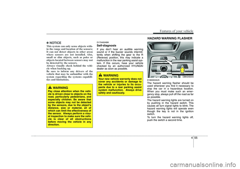
The hazard warning flasher should be
used whenever you find it necessary tostop the car in a hazardous location.
When you must make such an emer-
gency stop, always pull off the road as far
as possible.
The hazard warning lights are turned on
by pushing in the hazard switch. This
causes all turn signal lights to blink. The
hazard warning lights will operate even
though the key is not in the ignition
switch.
To turn the hazard warning lights off,
push the switch a second time.HAZARD WARNING FLASHER
OBK049044
WARNING
Pay close attention when the vehi-
cle is driven close to objects on the
road, particularly pedestrians, and
especially children. Be aware that
some objects may not be detected
by the sensors, due to the object’s
distance, size or material, all of
which can limit the effectiveness of
the sensor. Always perform a visu-al inspection to make sure the vehi-
cle is clear of all obstructions
before moving the vehicle in anydirection.
WARNING
Your new vehicle warranty does not
cover any accidents or damage to
the vehicle or injuries to its occu-pants due to a rear parking assist
system malfunction. Always drive
safely and cautiously.
Page 118 of 332
457
Features of your vehicle
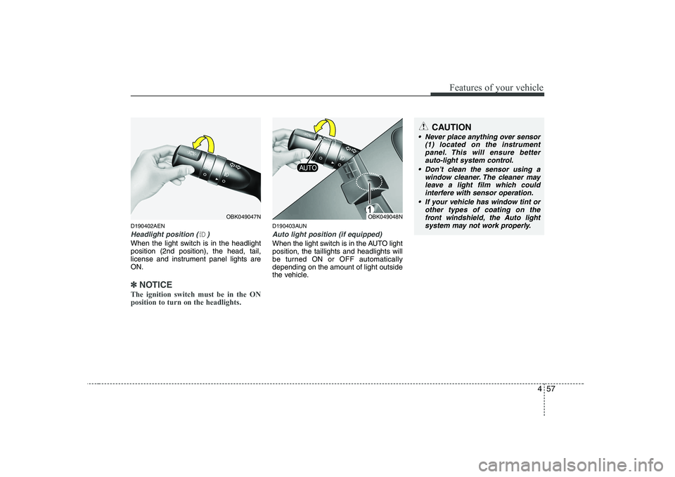
D190402AEN
Headlight position ( )
When the light switch is in the headlight position (2nd position), the head, tail,
license and instrument panel lights areON.
✽✽NOTICE
The ignition switch must be in the ON position to turn on the headlights.
D190403AUN
Auto light position (if equipped)
When the light switch is in the AUTO light position, the taillights and headlights will
be turned ON or OFF automaticallydepending on the amount of light outside
the vehicle.
OBK049048NOBK049047N
CAUTION
Never place anything over sensor (1) located on the instrumentpanel. This will ensure betterauto-light system control.
Don’t clean the sensor using a window cleaner. The cleaner mayleave a light film which couldinterfere with sensor operation.
If your vehicle has window tint or other types of coating on the
front windshield, the Auto light system may not work properly.
Page 137 of 332
Features of your vehicle
76
4
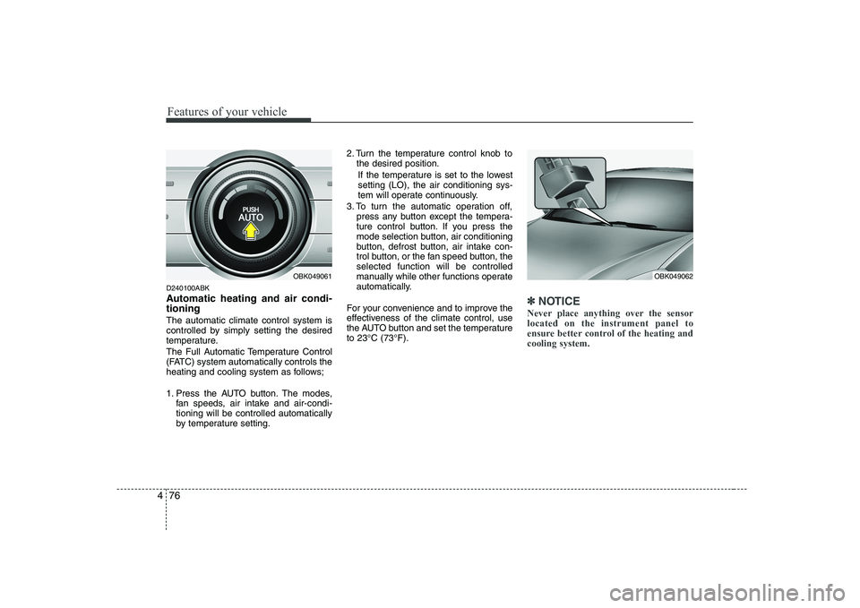
D240100ABK
Automatic heating and air condi- tioning The automatic climate control system is
controlled by simply setting the desired
temperature.
The Full Automatic Temperature Control
(FATC) system automatically controls the
heating and cooling system as follows;
1. Press the AUTO button. The modes,
fan speeds, air intake and air-condi- tioning will be controlled automatically
by temperature setting. 2. Turn the temperature control knob to
the desired position.
If the temperature is set to the lowestsetting (LO), the air conditioning sys-
tem will operate continuously.
3. To turn the automatic operation off, press any button except the tempera-
ture control button. If you press the
mode selection button, air conditioning
button, defrost button, air intake con-
trol button, or the fan speed button, theselected function will be controlled
manually while other functions operate
automatically.
For your convenience and to improve the
effectiveness of the climate control, use
the AUTO button and set the temperatureto 23°C (73°F).
✽✽ NOTICE
Never place anything over the sensor located on the instrument panel to
ensure better control of the heating andcooling system.
OBK049062OBK049061
Page 276 of 332
Maintenance
26
7
G170100AEN Filter inspection The climate control air filter should be replaced according to the Maintenance
Schedule. If the vehicle is operated in
severely air-polluted cities or on dusty
rough roads for a long period, it shouldbe inspected more frequently and
replaced earlier. When you replace the
climate control air filter, replace it per-
forming the following procedure, and be
careful to avoid damaging other compo-
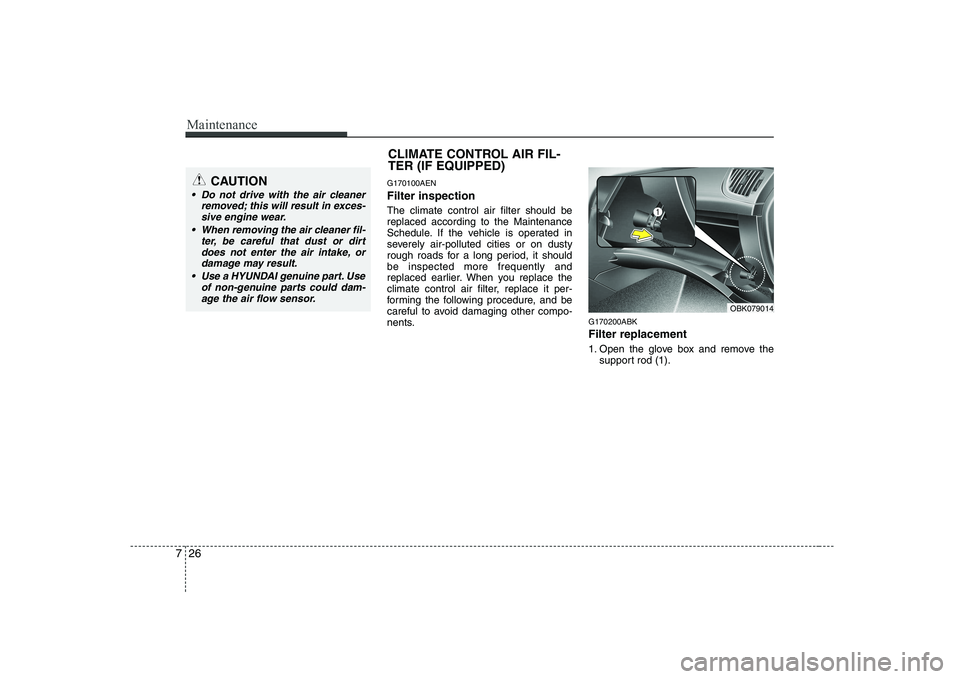
nents. G170200ABK Filter replacement
1. Open the glove box and remove the
support rod (1).CAUTION
Do not drive with the air cleaner
removed; this will result in exces-sive engine wear.
When removing the air cleaner fil- ter, be careful that dust or dirt
does not enter the air intake, ordamage may result.
Use a HYUNDAI genuine part. Use of non-genuine parts could dam-age the air flow sensor.
CLIMATE CONTROL AIR FIL-
TER (IF EQUIPPED)
OBK079014
Page 299 of 332
749
Maintenance
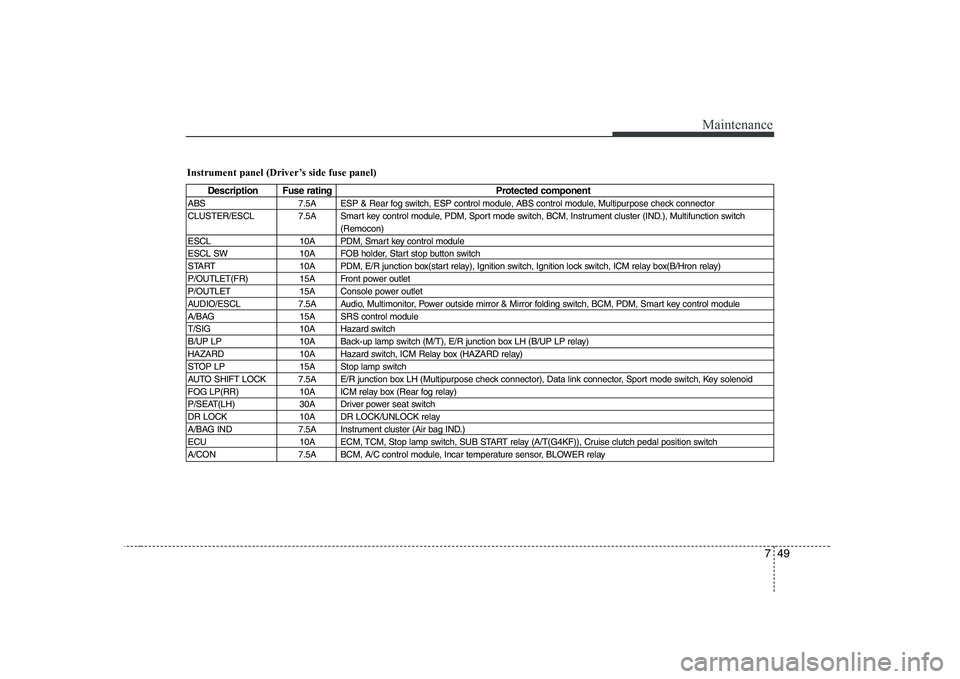
Instrument panel (Driver’s side fuse panel)
Description Fuse ratingProtected component
ABS 7.5A ESP & Rear fog switch, ESP control module, ABS control module, Multipurpose check connector
CLUSTER/ESCL 7.5A Smart key control module, PDM, Sport mode switch, BCM, Instrument cluster (IND.), Multifunction switch (Remocon)
ESCL 10A PDM, Smart key control module
ESCL SW 10A FOB holder, Start stop button switch
START 10A PDM, E/R junction box(start relay), Ignition switch, Ignition lock switch, ICM relay box(B/Hron relay)
P/OUTLET(FR) 15A Front power outlet
P/OUTLET 15A Console power outlet
AUDIO/ESCL 7.5A Audio, Multimonitor, Power outside mirror & Mirror folding switch, BCM, PDM, Smart key control module
A/BAG 15A SRS control module
T/SIG 10A Hazard switch
B/UP LP 10A Back-up lamp switch (M/T), E/R junction box LH (B/UP LP relay)
HAZARD 10A Hazard switch, ICM Relay box (HAZARD relay)
STOP LP 15A Stop lamp switch
AUTO SHIFT LOCK 7.5A E/R junction box LH (Multipurpose check connector), Data link connector, Sport mode switch, Key solenoid
FOG LP(RR) 10A ICM relay box (Rear fog relay)
P/SEAT(LH) 30A Driver power seat switch
DR LOCK 10A DR LOCK/UNLOCK relay
A/BAG IND 7.5A Instrument cluster (Air bag IND.)
ECU 10A ECM, TCM, Stop lamp switch, SUB START relay (A/T(G4KF)), Cruise clutch pedal position switch
A/CON 7.5A BCM, A/C control module, Incar temperature sensor, BLOWER relay
Page 300 of 332
Maintenance
50
7
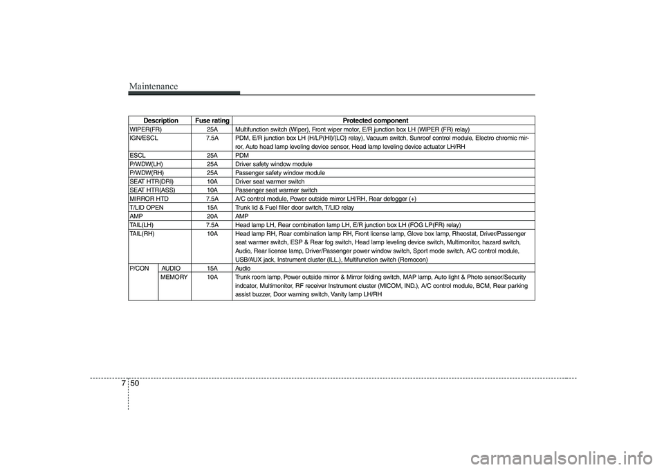
Description Fuse rating Protected component
WIPER(FR) 25A Multifunction switch (Wiper), Front wiper motor, E/R junction box LH (WIPER (FR) relay)
IGN/ESCL 7.5A PDM, E/R junction box LH (H/LP(HI)/(LO) relay), Vacuum switch, Sunroof control module, Electro chromic mir- ror, Auto head lamp leveling device sensor, Head lamp leveling device actuator LH/RH
ESCL 25A PDM
P/WDW(LH) 25A Driver safety window module
P/WDW(RH) 25A Passenger safety window module
SEAT HTR(DRI) 10A Driver seat warmer switch
SEAT HTR(ASS) 10A Passenger seat warmer switch
MIRROR HTD 7.5A A/C control module, Power outside mirror LH/RH, Rear defogger (+)
T/LID OPEN 15A Trunk lid & Fuel filler door switch, T/LID relay
AMP 20A AMP
TAIL(LH) 7.5A Head lamp LH, Rear combination lamp LH, E/R junction box LH (FOG LP(FR) relay)
TAIL(RH) 10A Head lamp RH, Rear combination lamp RH, Front license lamp, Glove box lamp, Rheostat, Driver/Passenger seat warmer switch, ESP & Rear fog switch, Head lamp leveling device switch, Multimonitor, hazard switch,
Audio, Rear license lamp, Driver/Passenger power window switch, Sport mode switch, A/C control module,
USB/AUX jack, Instrument cluster (ILL.), Multifunction switch (Remocon)
P/CON AUDIO 15A Audio MEMORY 10A Trunk room lamp, Power outside mirror & Mirror folding switch, MAP lamp, Auto light & Photo sensor/Security indcator, Multimonitor, RF receiver Instrument cluster (MICOM, IND.), A/C control module, BCM, Rear parking
assist buzzer, Door warning switch, Vanity lamp LH/RH
Page 302 of 332
Maintenance
52
7
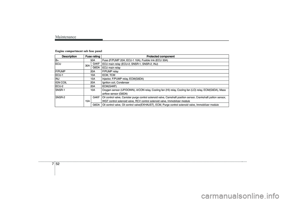
Engine compartment sub fuse panel
Description Fuse rating Protected component
B+ 50A Fuse (F/PUMP 20A, ECU-1 10A), Fusible link (ECU 30A)
ECU ECU main relay (ECU-2, SNSR-1, SNSR-2, INJ) ECU main relay
F/PUMP 20A F/PUMP relay
ECU-1 10A ECM, TCM
INJ 15A Injector, F/PUMP relay, ECM(G6DA)
IGN COIL 20A Ignition coil, Condenser
ECU-2 20A ECM(G4KF)
SNSR-1 10A Oxygen sensor (UP/DOWN), A/CON relay, Cooling fan (HI) relay, Cooling fan (LO) relay, ECM(G6DA), Mass airflow sensor (G6DA)
SNSR-2 Oil control valve, Canister purge control solenoid valve, Camshaft position sensor, Crankshaft psition sensor, WGT control solenoid valve, RCV control solenoid valve, Immobilizer moduleOil control valve, Oil control valve(EXHAUST), ECM, Purge control solenoid valve, Immobilizer module
30A G4KF
G6DA
15A G4KF
G6DA