park assist HYUNDAI GENESIS G90 2019 Owner's Manual
[x] Cancel search | Manufacturer: HYUNDAI, Model Year: 2019, Model line: GENESIS G90, Model: HYUNDAI GENESIS G90 2019Pages: 538, PDF Size: 13.02 MB
Page 360 of 538
5-108
• The vehicle stops and goes repeat-
edly for a long period of time.
• The accelerator pedal is continu-
ously depressed for a long period
of time.
• The engine performance is abnor-
mal.
• Engine rpm is in the red zone.
• The driver starts driving by pushing
the toggle switch up (RES+)/down
(SET-) or depressing the accelera-
tor pedal, after the vehicle is
stopped by the Smart Cruise
Control system with no other vehi-
cle ahead.
• The driver starts driving by pushing
the toggle switch up (RES+)/down
(SET-) or depressing the accelera-
tor pedal, after stopping the vehicle
with a vehicle stopped far away in
front.
• The braking control is operated for
FCA (Forward Collision-Avoidance
Assist)
• The engine is stopped by ISG (Idle
Stop & Go) (if equipped).
Each of these actions will cancel the
Smart Cruise Control operation. The
Set Speed and Vehicle-to-Vehicle
Distance on the cluster LCD display
will go off.
In a condition the Smart Cruise
Control is canceled automatically,
the Smart Cruise Control will not
resume even though the RES+ or
SET- toggle switch is pushed.
Also, if the Smart Cruise Control is
canceled automatically while the
vehicle is at a standstill, EPB
(Electronic Parking Brake) will be
applied.Information
If the Smart Cruise Control is can-
celed during a situation that is not
described, have the system checked by
an authorized retailer of Genesis
Branded products.
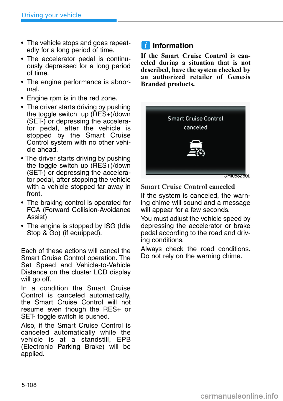
Smart Cruise Control canceled
If the system is canceled, the warn-
ing chime will sound and a message
will appear for a few seconds.
You must adjust the vehicle speed by
depressing the accelerator or brake
pedal according to the road and driv-
ing conditions.
Always check the road conditions.
Do not rely on the warning chime.
i
OHI058260L
Driving your vehicle
Page 419 of 538
6-5
06
Information
An inappropriately disposed
battery can be harmful to the
environment and human
health. Dispose of the battery
according to your local law(s)
or regulations.
To prevent damage to your vehi-
cle:
• Only use a 12-volt power supply
(battery or jumper system) to
jump start your vehicle.
• Do not attempt to jump start
your vehicle by push-starting.
Jump starting procedure
Information
Your vehicle has a battery in the trunk
compartment, but when you jump
start your vehicle, use the jumper ter-
minal in the engine compartment.
1. Position the vehicles close enough
that the jumper cables will reach,
but do not allow the vehicles to
touch.
2. Avoid fans or any moving parts in
the engine compartment at all
times, even when the vehicles are
turned off.
3. Turn off all electrical devices such
as radios, lights, air conditioning,
etc. Put the vehicles in P (Park)
and set the parking brakes. Turn
both vehicles OFF.
4. Open the engine hood.5. Open the small service cover with
a screwdriver.
6. Remove the engine compartment
fuse box cover.
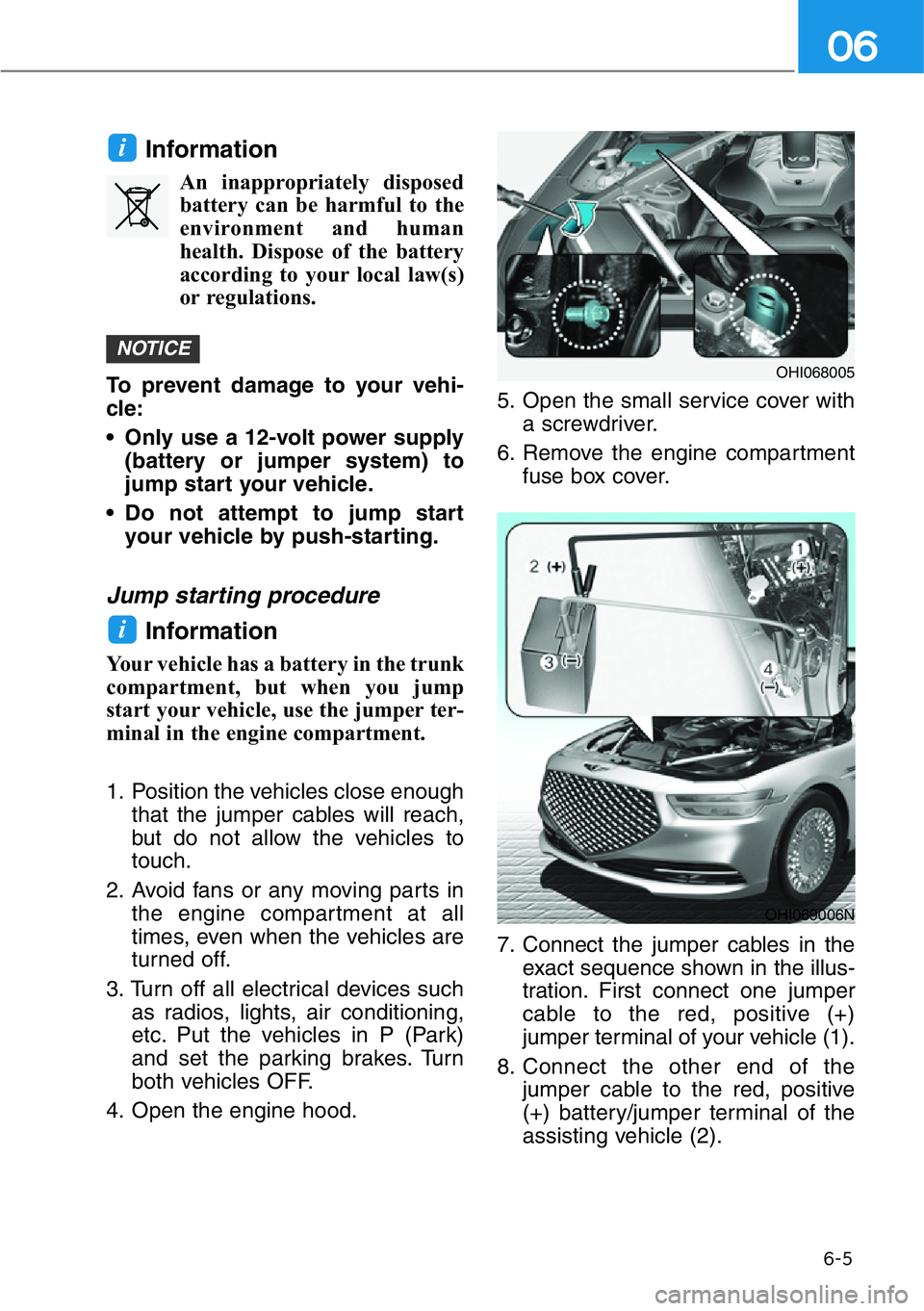
7. Connect the jumper cables in the
exact sequence shown in the illus-
tration. First connect one jumper
cable to the red, positive (+)
jumper terminal of your vehicle (1).
8. Connect the other end of the
jumper cable to the red, positive
(+) battery/jumper terminal of the
assisting vehicle (2).
i
NOTICE
i
OHI069006N
OHI068005
Page 421 of 538
6-7
06
If your temperature gauge indicates
overheating, you experience a loss
of power, or hear loud pinging or
knocking, the engine may be over-
heating. If this happens, you should:
1. Pull off the road and stop as soon
as it is safe to do so.
2. Shift the gear to P (Park) and set
the parking brake. If the air condi-
tioning is ON, turn it OFF.
3. If engine coolant is running out
under the vehicle or steam is com-
ing out from the hood, stop the
engine. Do not open the hood until
the coolant has stopped running
or the steaming has stopped. If
there is no visible loss of engine
coolant and no steam, leave the
engine running and check to be
sure the engine cooling fan is
operating. If the fan is not running,
turn the engine off.4. Check for coolant leaking from the
radiator, hoses or under the vehi-
cle. (If the air conditioning had
been in use, it is normal for cold
water to be draining from it when
you stop.)
5. If engine coolant is leaking out,
stop the engine immediately and
call the nearest authorized retailer
of Genesis Branded products for
assistance.
IF THE ENGINE OVERHEATS
While the engine is
running, keep hands,
clothing and tools
away from the moving
parts such as the
cooling fan and drive
belt to prevent seri-
ous injury.
WARNING
Page 497 of 538
7-57
07
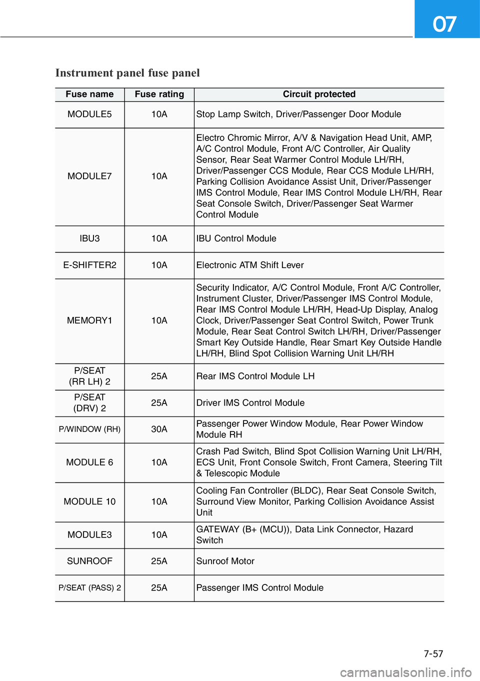
Instrument panel fuse panel
Fuse name Fuse rating Circuit protected
MODULE5 10AStop Lamp Switch, Driver/Passenger Door Module
MODULE7 10A
Electro Chromic Mirror, A/V & Navigation Head Unit, AMP,
A/C Control Module, Front A/C Controller, Air Quality
Sensor, Rear Seat Warmer Control Module LH/RH,
Driver/Passenger CCS Module, Rear CCS Module LH/RH,
Parking Collision Avoidance Assist Unit, Driver/Passenger
IMS Control Module, Rear IMS Control Module LH/RH, Rear
Seat Console Switch, Driver/Passenger Seat Warmer
Control Module
IBU3 10AIBU Control Module
E-SHIFTER2 10AElectronic ATM Shift Lever
MEMORY1 10A
Security Indicator, A/C Control Module, Front A/C Controller,
Instrument Cluster, Driver/Passenger IMS Control Module,
Rear IMS Control Module LH/RH, Head-Up Display, Analog
Clock, Driver/Passenger Seat Control Switch, Power Trunk
Module, Rear Seat Control Switch LH/RH, Driver/Passenger
Smart Key Outside Handle, Rear Smart Key Outside Handle
LH/RH, Blind Spot Collision Warning Unit LH/RH
P/SEAT
(RR LH) 225ARear IMS Control Module LH
P/SEAT
(DRV) 225ADriver IMS Control Module
P/WINDOW (RH)30APassenger Power Window Module, Rear Power Window
Module RH
MODULE 610ACrash Pad Switch, Blind Spot Collision Warning Unit LH/RH,
ECS Unit, Front Console Switch, Front Camera, Steering Tilt
& Telescopic Module
MODULE 10 10ACooling Fan Controller (BLDC), Rear Seat Console Switch,
Surround View Monitor, Parking Collision Avoidance Assist
Unit
MODULE3 10AGATEWAY (B+ (MCU)), Data Link Connector, Hazard
Switch
SUNROOF 25ASunroof Motor
P/SEAT (PASS) 225APassenger IMS Control Module
Page 498 of 538
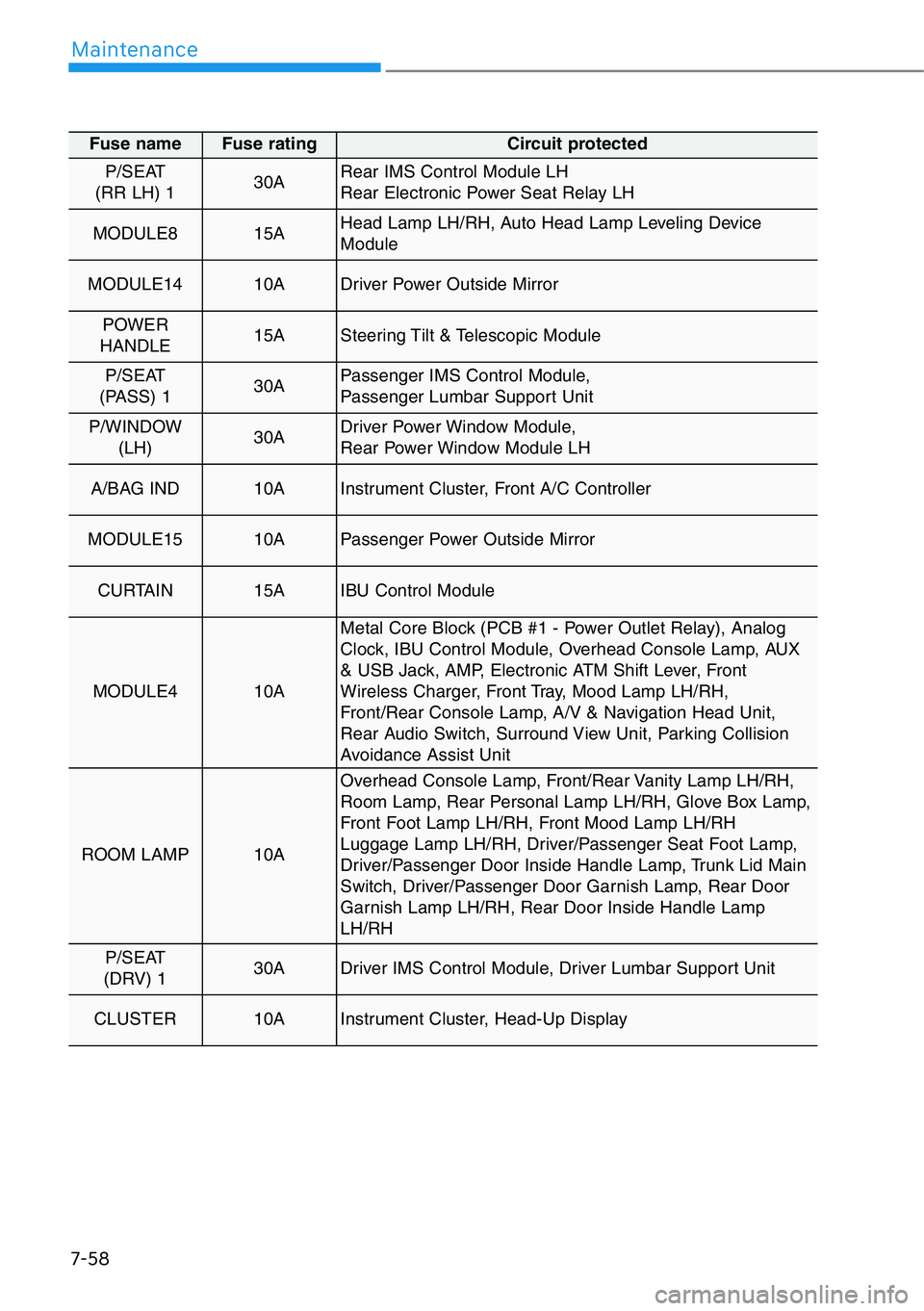
7-58
Maintenance
Fuse name Fuse rating Circuit protected
P/SEAT
(RR LH) 130ARear IMS Control Module LH
Rear Electronic Power Seat Relay LH
MODULE8 15AHead Lamp LH/RH, Auto Head Lamp Leveling Device
Module
MODULE1410ADriver Power Outside Mirror
POWER
HANDLE 15ASteering Tilt & Telescopic Module
P/SEAT
(PASS) 130APassenger IMS Control Module,
Passenger Lumbar Support Unit
P/WINDOW
(LH)30ADriver Power Window Module,
Rear Power Window Module LH
A/BAG IND10AInstrument Cluster, Front A/C Controller
MODULE1510APassenger Power Outside Mirror
CURTAIN 15AIBU Control Module
MODULE4 10A
Metal Core Block (PCB #1 - Power Outlet Relay), Analog
Clock, IBU Control Module, Overhead Console Lamp, AUX
& USB Jack, AMP, Electronic ATM Shift Lever, Front
Wireless Charger, Front Tray, Mood Lamp LH/RH,
Front/Rear Console Lamp, A/V & Navigation Head Unit,
Rear Audio Switch, Surround View Unit, Parking Collision
Avoidance Assist Unit
ROOM LAMP 10A
Overhead Console Lamp, Front/Rear Vanity Lamp LH/RH,
Room Lamp, Rear Personal Lamp LH/RH, Glove Box Lamp,
Front Foot Lamp LH/RH, Front Mood Lamp LH/RH
Luggage Lamp LH/RH, Driver/Passenger Seat Foot Lamp,
Driver/Passenger Door Inside Handle Lamp, Trunk Lid Main
Switch, Driver/Passenger Door Garnish Lamp, Rear Door
Garnish Lamp LH/RH, Rear Door Inside Handle Lamp
LH/RH
P/SEAT
(DRV) 130ADriver IMS Control Module, Driver Lumbar Support Unit
CLUSTER 10AInstrument Cluster, Head-Up Display