tow Hyundai Getz 2003 Service Manual
[x] Cancel search | Manufacturer: HYUNDAI, Model Year: 2003, Model line: Getz, Model: Hyundai Getz 2003Pages: 444, PDF Size: 13.82 MB
Page 275 of 444

FEATURES OF YOUR HYUNDAI 1- 15
!WARNING:
o When you return the folded down seatback to its upright position, make sure the seat belts are in position to be accessible and to function properly.
o When you return the folded down seatback to its upright position,be careful not to get your fingersor legs caught in the mechanism.
o The purpose of the fold down
rear seatback and the fold for-ward rear seat cushion is to in- crease cargo space. Do not allow passengers to sit in the cargoarea while the car is moving. This is not a proper seating position
3. Pull the seat cushion release handle
rear ward, then lift up a desired seatcushion.
4. To secure the seat, hook the secur-ing strap under the seat back to the headrest stay of front driver andpassenger seat.
5. To return the seatback and seat
cushion to its normal position, re-verse the above procedure.
o When you return the seatback to its
upright position, always be sure it islocked into position by pulling and pushing on the top of seatback.
HTB030A
Seat cushion release handle
HTB031Securing strap
Securing Strap
HTB029Seatback folding lever
B090B01TB-EAT Folding Rear Seatback and Seat Cushion For greater convenience, the entire seatback and seat cushion may be folded down and up.
1. Push the headrest down to the low- est position.
2. To fold down the seatback , push and hold the seatback folding lever toward the headrest, then push down the seatback.
Page 278 of 444
1- 18 FEATURES OF YOUR HYUNDAI
!
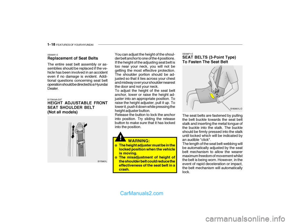
SB090P1-E SEAT BELTS (3-Point Type) To Fasten The Seat Belt
B180A01L-D
The seat belts are fastened by pulling the belt buckle towards the seat belt stalk and inserting the metal tongue of the buckle into the stalk. The buckleshould be firmly pressed into the stalk until locked which will be indicated by an audible "click".The length of the seat belt webbing will be automatically adjusted by the seat belt mechanism to allow the wearermaximum freedom of movement whilst the belt is being worn. However, in the event of rapid deceleration or impact,the belt mechanism will automatically lock.
B170A01L
SB090K1-E Replacement of Seat Belts The entire seat belt assembly or as- semblies should be replaced if the ve- hicle has been involved in an accident even if no damage is evident. Addi-tional questions concerning seat belt operation should be directed to a Hyundai Dealer. B170A04A-EAT HEIGHT ADJUSTABLE FRONT SEAT SHOULDER BELT(Not all models)
You can adjust the height of the shoul- der belt anchor to one of the 4 positions. If the height of the adjusting seat belt istoo near your neck, you will not be getting the most effective protection. The shoulder portion should be ad-justed so that it lies across your chest and midway over your shoulder nearest the door and not your neck.To adjust the height of the seat belt anchor, lower or raise the height ad- juster into an appropriate position. Toraise the height adjuster, pull it up. To lower it, push it down while pressing the height adjuster button.Release the button to lock the anchor into position. Try sliding the release button to make sure that it has lockedinto the position.
WARNING:
o The height adjuster must be in the locked position when the vehicle is moving.
o The misadjustment of height of the shoulder belt could reduce theeffectiveness of the seat belt in a crash.
Page 283 of 444
FEATURES OF YOUR HYUNDAI 1- 23
!WARNING:
Do not install any child restraint sys- tem in the front passenger seat. Should an accident occur and cause the passenger side airbag to deploy,it could severely injure or kill an infant or child seated in an infant or child seat. Therefore, only use a childrestraint system in the rear seat of your vehicle.
If you need to tighten the belt, pull morewebbing toward the retractor. When you unbuckle the seat belt and allow it toretract, the retractor will automatically revert back to its normal seated pas- senger emergency locking usage con-dition. NOTE:
o Before installing the child restraint
system, read the instructions sup- plied by the child restraint system manufacturer.
o If the seat belt does not operate as described, have the systemchecked immediately by your au-thorized Hyundai dealer.
B230B01TB
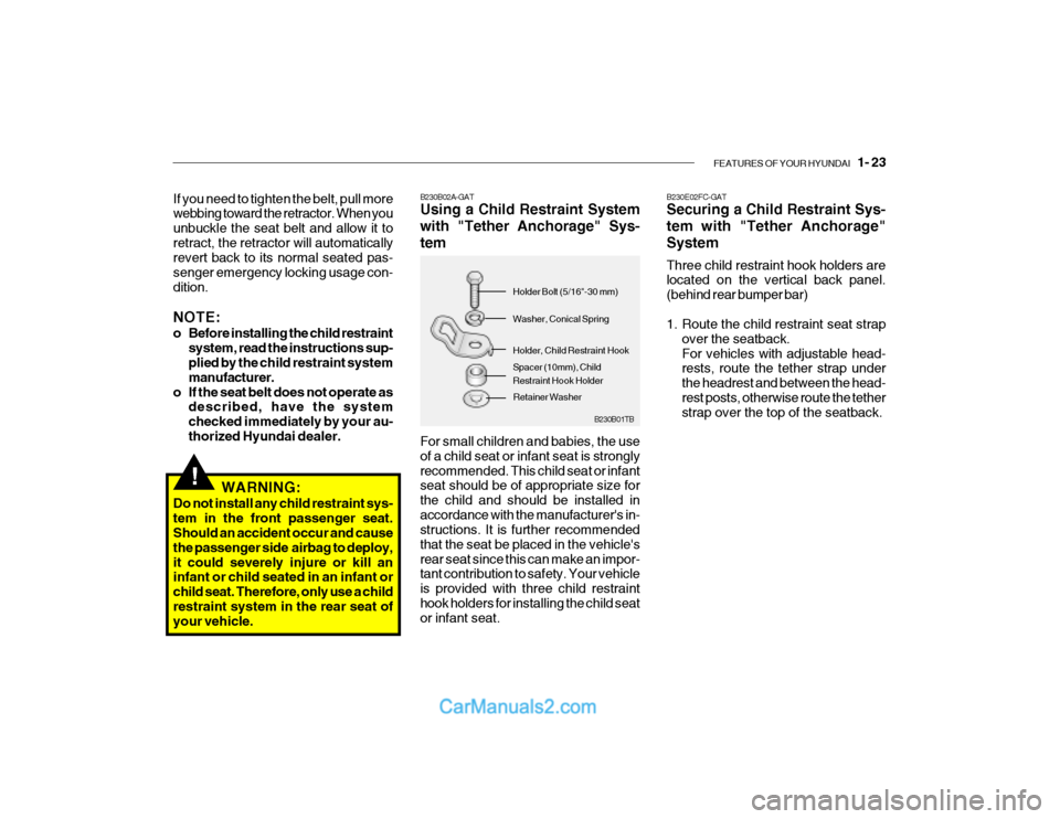
B230B02A-GAT Using a Child Restraint System with "Tether Anchorage" Sys-tem For small children and babies, the use of a child seat or infant seat is stronglyrecommended. This child seat or infant seat should be of appropriate size for the child and should be installed inaccordance with the manufacturer's in- structions. It is further recommended that the seat be placed in the vehicle'srear seat since this can make an impor- tant contribution to safety. Your vehicle is provided with three child restrainthook holders for installing the child seat or infant seat. Spacer (10mm), Child Restraint Hook Holder
Holder Bolt (5/16"-30 mm) Washer, Conical Spring Holder, Child Restraint Hook
Retainer Washer B230E02FC-GAT Securing a Child Restraint Sys- tem with "Tether Anchorage"System Three child restraint hook holders are located on the vertical back panel. (behind rear bumper bar)
1. Route the child restraint seat strap
over the seatback. For vehicles with adjustable head- rests, route the tether strap under the headrest and between the head-rest posts, otherwise route the tether strap over the top of the seatback.
Page 294 of 444
1- 34 FEATURES OF YOUR HYUNDAI
!
B240C02L
WARNING:
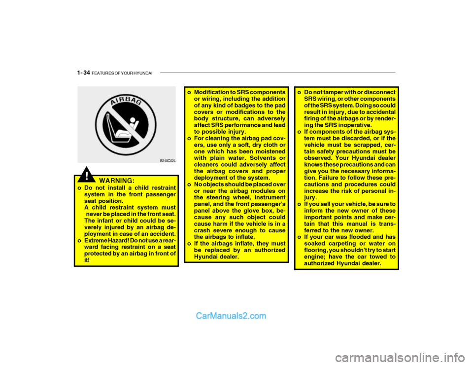
o Do not install a child restraint system in the front passenger seat position. A child restraint system must
never be placed in the front seat.The infant or child could be se- verely injured by an airbag de- ployment in case of an accident.
o Extreme Hazard! Do not use a rear- ward facing restraint on a seatprotected by an airbag in front ofit! o Modification to SRS components
or wiring, including the additionof any kind of badges to the padcovers or modifications to the body structure, can adversely affect SRS performance and leadto possible injury.
o For cleaning the airbag pad cov-
ers, use only a soft, dry cloth orone which has been moistened with plain water. Solvents or cleaners could adversely affectthe airbag covers and proper deployment of the system.
o No objects should be placed over
or near the airbag modules onthe steering wheel, instrument panel, and the front passenger'spanel above the glove box, be- cause any such object could cause harm if the vehicle is in acrash severe enough to cause the airbags to inflate.
o If the airbags inflate, they must
be replaced by an authorizedHyundai dealer. o Do not tamper with or disconnect
SRS wiring, or other components of the SRS system. Doing so couldresult in injury, due to accidental firing of the airbags or by render- ing the SRS inoperative.
o If components of the airbag sys- tem must be discarded, or if thevehicle must be scrapped, cer-tain safety precautions must be observed. Your Hyundai dealer knows these precautions and cangive you the necessary informa- tion. Failure to follow these pre- cautions and procedures couldincrease the risk of personal in- jury.
o If you sell your vehicle, be sure to inform the new owner of theseimportant points and make cer- tain that this manual is trans-ferred to the new owner.
o If your car was flooded and has
soaked carpeting or water onflooring, you shouldn't try to start engine; have the car towed to authorized Hyundai dealer.
Page 299 of 444

FEATURES OF YOUR HYUNDAI 1- 39
SB210M1-E
CHARGING SYSTEM WARNING LIGHT
The charging system warning light should illuminate when the ignitionswitch is turned to the "ON" position and should be extinguished when the engine is started. If the light fails toilluminate when the ignition is turned "ON" or fails to extinguish after starting the engine, the nearest Hyundai dealershould be contacted. If the light illumi- nates whilst the vehicle is being driven, stop the vehicle as soon as it is safe todo so and check the condition of the generator drive belt. If the belt is in SB2100I-E
DOOR AJAR WARNING LIGHT
The door ajar warning light indicates that a door is not correctly closed. Ensure that the light is extinguishedprior to driving the vehicle.
B260B01FC-EAT
TAIL GATE OPEN WARNING LIGHT
The tail gate warning light indicates when the tail gate is open or is not fullyclosed. Ensure that the light has extin- guished prior to driving the vehicle. SB210P1-E
LOW FUEL LEVEL WARNING LIGHT
The low fuel warning light serves to warn the driver that the remaining fuel quantity is approximately 9 litres and that the vehicle should be refuelled. Ifthe vehicle is driven for an extended period with the low fuel warning light illuminated there exists a possibilitythat misfiring due to fuel shortage may occur. This situation must be avoided to prevent damage to the catalyst oc-curring.
recommended to assist in bringing the vehicle to rest. The vehicle must not be driven once brake failure has occurreduntil the system has been repaired and is functioning normally. The braking system employs a vacuumservo in order that the pedal efforts are reduced. Power for the servo is derived from the engine and therefore, in theevent of the engine stopping or the vehicle being towed, pedal efforts will be substantially increased.
place and the tension is satisfactory, the advice of a Hyundai dealer should be sought.
CAUTION:
If the drive belt (generator belt) is loose, broken, or missing while the vehicle is driving, there may be aserious malfunction, engine could overheat because this belt also drives the water pump.
!
B260N02FC-EAT MALFUNCTION INDICA- TOR LIGHT
This light illuminates when there is a malfunction of an exhaust gas related component, and the system is not func-tioning properly so that the exhaust gas regulation values are not satisfied. This light will illuminate when the ignition keyis tuned to the "ON" position, and will go out after the engine start. If it illumi- nates while driving, or does not illumi-nate when the ignition key is turned to the "ON" position, take your car to your
Page 306 of 444
1- 46 FEATURES OF YOUR HYUNDAI
HTB014B
MPG = Total Cruise Distance(Miles) Total Fuel Consumption (G)
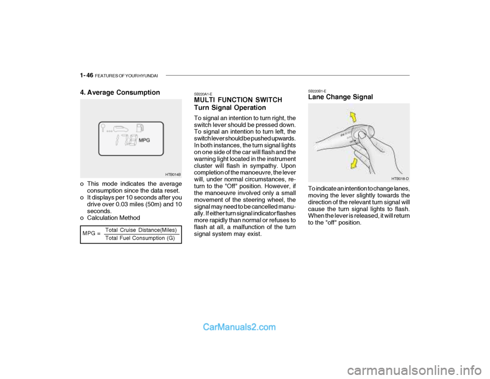
4. Average Consumption
o This mode indicates the average
consumption since the data reset.
o It displays per 10 seconds after you
drive over 0.03 miles (50m) and 10 seconds.
o Calculation Method SB220A1-E MULTI FUNCTION SWITCH Turn Signal Operation To signal an intention to turn right, the switch lever should be pressed down. To signal an intention to turn left, the switch lever should be pushed upwards.In both instances, the turn signal lights on one side of the car will flash and the warning light located in the instrumentcluster will flash in sympathy. Upon completion of the manoeuvre, the lever will, under normal circumstances, re-turn to the "Off" position. However, if the manoeuvre involved only a small movement of the steering wheel, thesignal may need to be cancelled manu- ally. If either turn signal indicator flashes more rapidly than normal or refuses toflash at all, a malfunction of the turn signal system may exist. SB220B1-E Lane Change Signal To indicate an intention to change lanes, moving the lever slightly towards the direction of the relevant turn signal willcause the turn signal lights to flash. When the lever is released, it will return to the "off" position.
HTB018-D
Page 307 of 444
FEATURES OF YOUR HYUNDAI 1- 47
HTB017-DHTB015-D
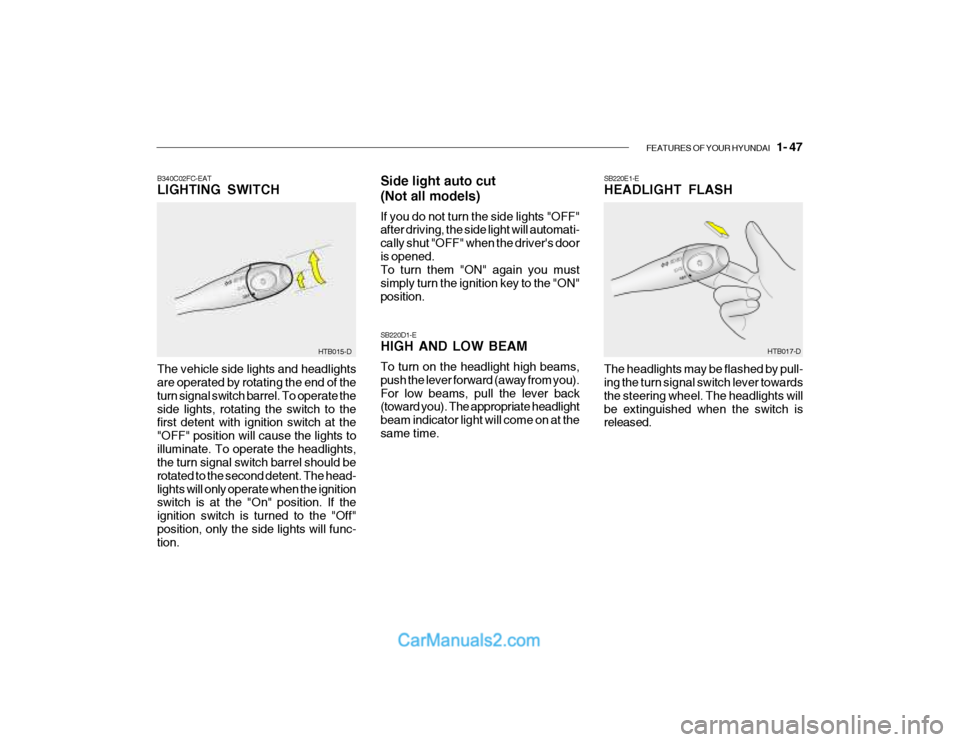
B340C02FC-EAT LIGHTING SWITCH
The vehicle side lights and headlights are operated by rotating the end of the turn signal switch barrel. To operate theside lights, rotating the switch to the first detent with ignition switch at the "OFF" position will cause the lights toilluminate. To operate the headlights, the turn signal switch barrel should be rotated to the second detent. The head-lights will only operate when the ignition switch is at the "On" position. If the ignition switch is turned to the "Off"position, only the side lights will func- tion. Side light auto cut (Not all models) If you do not turn the side lights "OFF" after driving, the side light will automati- cally shut "OFF" when the driver's dooris opened. To turn them "ON" again you must simply turn the ignition key to the "ON"position. SB220D1-E HIGH AND LOW BEAM To turn on the headlight high beams, push the lever forward (away from you). For low beams, pull the lever back (toward you). The appropriate headlight beam indicator light will come on at thesame time.
SB220E1-E HEADLIGHT FLASH The headlights may be flashed by pull- ing the turn signal switch lever towards the steering wheel. The headlights willbe extinguished when the switch is released.
Page 308 of 444
1- 48 FEATURES OF YOUR HYUNDAI
HTB019-D
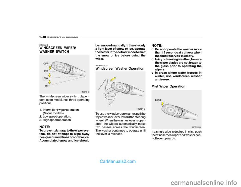
SB230A1-E WINDSCREEN WIPER/ WASHER SWITCH The windscreen wiper switch, depen- dent upon model, has three operating positions.
1. Intermittent wiper operation.
(Not all models)
2. Low speed operation.
3. High speed operation. NOTE: To prevent damage to the wiper sys- tem, do not attempt to wipe away heavy accumulations of snow or ice. Accumulated snow and ice should be removed manually. If there is only a light layer of snow or ice, operate the heater in the defrost mode to meltthe snow or ice before using the wiper.
NOTE:
o Do not operate the washer more
than 15 seconds at a time or when the fluid reservoir is empty.
o In icy or freezing weather, be sure the wiper blades are not frozen tothe glass prior to operating thewipers.
o In areas where water freezes in
winter, use windscreen washerantifreeze.
Mist Wiper Operation
HTB022-D
To use the windscreen washer, pull the wiper/washer lever toward the steeringwheel. When the washer lever is oper- ated, the wipers automatically make two passes across the windscreen.The washer continues to operate until the lever is released.
B350B01O-EAT Windscreen Washer Operation
HTB021-DIf a single wipe is desired in mist, push the windscreen wiper and washer con-trol lever upwards.
Page 319 of 444

FEATURES OF YOUR HYUNDAI 1- 59
!
SB370A1-E INTERIOR REAR VIEW MIRROR The interior mirror is of the day/night type to enable the glare of headlights from following vehicles to be eliminatedduring night time driving. The tab located at the bottom of the mirror should be set to the positionnearest the windscreen for normal day time driving, and flipped towards the rear of the vehicle to eliminate glareduring night time driving. To adjust the field of vision, the mirror may be moved by hand upon the mounting. NOTE: The mirror should always be ad- justed prior to setting the vehicle inmotion. HTB103B510D01HP-EAT OUTSIDE REARVIEW MIRROR HEATER (Not all models) The outside rearview mirror heater is actuated in connection with the rear window defroster. To heat the outsiderearview mirror glass, push in the switch for the rear window defroster. The rear- view mirror glass will be heated fordefrosting or defogging and will give you improved rear vision in inclement weather conditions. Push the switchagain to turn the heater off. The outside rearview mirror heater automatically turns itself off after 20 minutes. SB360C1-F FOLDING THE OUTSIDE REAR VIEW MIRRORS To fold the outside rear view mirrors, push them towards the rear. The outside rear view mirrors can befolded rearward for parking in restricted areas.
HTB039
HTB205
WARNING:
Do not adjust or fold the outside rear view mirrors while the vehicle ismoving. This could result in loss of control, and an accident causing death, serious injury or propertydamage.
Page 335 of 444
FEATURES OF YOUR HYUNDAI 1- 75
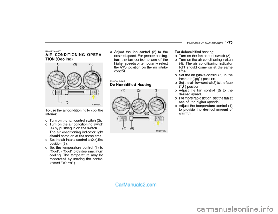
B740B02A-AAT AIR CONDITIONING OPERA- TION (Cooling)
B740C01A-AAT De-Humidified Heating
To use the air conditioning to cool the interior:
o Turn on the fan control switch (2).
o Turn on the air conditioning switch(4) by pushing in on the switch.The air conditioning indicator lightshould come on at the same time.
o Set the air intake control to the
position (5).
o Set the temperature control (1) to "Cool". ("Cool" provides maximumcooling. The temperature may bemoderated by moving the control toward "Warm".) HTB046-D
o Adjust the fan control (2) to the
desired speed. For greater cooling, turn the fan control to one of thehigher speeds or temporarily select
the position on the air intake control. For dehumidified heating:
o Turn on the fan control switch (2).
o Turn on the air conditioning switch
(4). The air conditioning indicator light should come on at the same time.
o Set the air intake control (5) to the fresh air ( ) position.
o Set the air flow control (3) to the face ( ) position.
o Adjust the fan control (2) to the
desired speed.
o For more rapid action, set the fan at one of the higher speeds.
o Adjust the temperature control (1)
to provide the desired amount of warmth.
(1)
(2)
(3)
(4) (5)
HTB046-D
(1)
(2)
(3)
(4) (5)