coolant temperature Hyundai Getz 2004 User Guide
[x] Cancel search | Manufacturer: HYUNDAI, Model Year: 2004, Model line: Getz, Model: Hyundai Getz 2004Pages: 445, PDF Size: 12.16 MB
Page 216 of 445
DO-IT-YOURSELF MAINTENANCE 6- 29
o If battery fluid is on your skin, flush
the affected areas with water for at least 15 minutes and then seekmedical assistance.
o If battery fluid is in your eyes, rinse
out your eyes with water and getmedical assistance as soon as pos- sible. While you are being driven to get medical assistance, continue torinse your eyes by using a sponge or soft cloth saturated with water.
o If you swallow battery fluid, drink a large quantity of water or milk fol-lowed by milk of magnesia, eat a raw egg or drink vegetable oil. Getmedical assistance as soon as pos- sible.
While batteries are being charged (ei-ther by a battery charger or by the vehicle's alternator), they produce ex-plosive gases. Always observe these warnings to prevent injuries from oc- curring:
o Charge batteries only in a well ven- tilated area.
o Do not permit flames, sparks or smoking in the area.
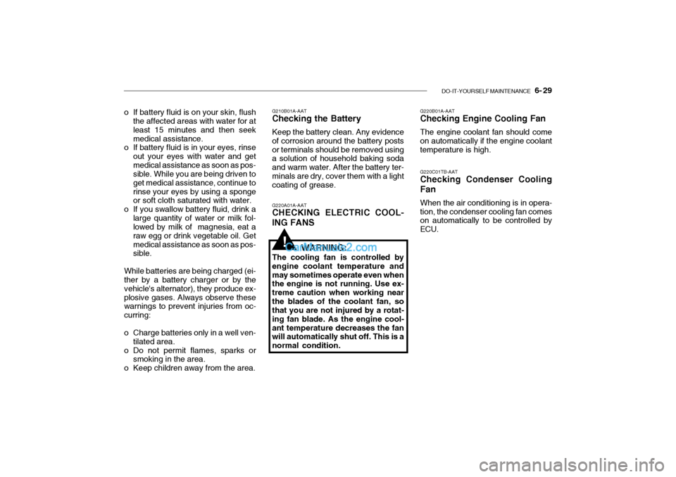
o Keep children away from the area. G220B01A-AAT Checking Engine Cooling Fan The engine coolant fan should come on automatically if the engine coolanttemperature is high. G220C01TB-AAT Checking Condenser Cooling Fan When the air conditioning is in opera- tion, the condenser cooling fan comes on automatically to be controlled by ECU.
G210B01A-AAT Checking the Battery Keep the battery clean. Any evidence of corrosion around the battery postsor terminals should be removed using a solution of household baking soda and warm water. After the battery ter-minals are dry, cover them with a light coating of grease. G220A01A-AAT CHECKING ELECTRIC COOL- ING FANS
WARNING:
The cooling fan is controlled by engine coolant temperature andmay sometimes operate even when the engine is not running. Use ex- treme caution when working nearthe blades of the coolant fan, so that you are not injured by a rotat- ing fan blade. As the engine cool-ant temperature decreases the fan will automatically shut off. This is a normal condition.
!
Page 229 of 445
7- 2 EMISSION CONTROL SYSTEMS
H010A01A-GAT
EMISSION CONTROL SYSTEM (If Installed)
Your Hyundai is equipped with an
emission control system to meet all requirements of the Emission prohibi- tion rules of your province.
There are three emission control sys-
tems which are as follows.
1) Crankcase emission control sys-
tem
2) Evaporative emission control sys- tem
3) Exhaust emission control system
In order to assure the proper function
of the emission control systems, it is recommended that you have your carinspected and maintained by an au- thorized Hyundai dealer in accordance with the maintenance schedule in thismanual. H010B01A-AAT
1. Crankcase Emission Control
System
The positive crankcase ventilation
system is employed to prevent airpollution caused by blow-by gases being emitted from the crankcase. This system supplies fresh air to thecrankcase through the air intake hose. Inside the crankcase, the fresh air mixes with blow-by gases, which thenpass through the PCV valve and into the induction system.
H010C01E-GAT
2. Evaporative Emission Con- trol System
The Evaporative Emission Control
System is designed to prevent fuel vapors from escaping into the atmo-sphere. Canister
While the engine is inoperative, fuel
vapors generated inside the fuel tank are absorbed and stored in the canis- ter. When the engine is running, the fuel vapors absorbed in the canister are drawn into the induction system through
the purge control solenoid valve.
Purge Control Solenoid Valve (PCSV) The purge control solenoid valve is
controlled by the Engine Control Mod- ule (ECM); when the engine coolanttemperature is low during idling, the PCSV closes so that evaporated fuel is not taken into the engine. After theengine warms-up during ordinary driv- ing, the PCSV opens so as to intro- duce evaporated fuel to the engine. H010D01A-AAT
3. Exhaust Emission Control
System
The exhaust emission control system is a highly effective system whichcontrols exhaust emission while main- taining good vehicle performance.
Page 244 of 445

INDEX 10- 3
D Defrosting / Defogging .............................................. 1-80
Door Door locks ................................................................ 1-7
Locking, unlocking front doors with a key ............... 1-7
Drink Holder .............................................................. 1-59
Drive Belts ................................................................ 6-25
Driving
Economical driving ................................................. 2-14
Smooth cornering ................................................... 2-15
Winter driving ......................................................... 2-15
EEmission Control Syst em ........................................... 7-2
Engine Before starting the engine ....................................... 2-3
Compartment ........................................................... 6-2
Coolant ................................................................... 6-13
Coolant temperature gauge ................................... 1-49
If the engine overheats ............................................ 3-4
Number .................................................................... 8-2
Oil ............................................................................. 6-7
Starting ..................................................................... 2-3
Engine Exhaust Can Be Dangerous ........................... 2-2F Fog Light
Front ....................................................................... 1-57
Rear ....................................................................... 1-57
Front Seats Adjustable front seats ............................................ 1-13
Adjustable headrest s .............................................. 1-14
Adjusting seat forward and rear ward..................... 1-13
Adjusting seatback angle .......................................1-13
Lumbar support control .................. ........................ 1-14
Seat cushion height adjustment............................ 1-15
Seat warmer ........................................................... 1-19
Fuel Capacity ................................................................... 9-2
Gauge .................................................................... 1-48
recommendations ..................................................... 1-2
Fuel Filler Lid Remote release ...................................................... 1-68
Fuses ........................................................................ 6-26
Fuse Panel description ............................................. 6-38
G General Checks .......................................................... 6-6
Glove Box ................................................................. 1-63
Page 302 of 445
1- 44 FEATURES OF YOUR HYUNDAI
!
SB215B1-E
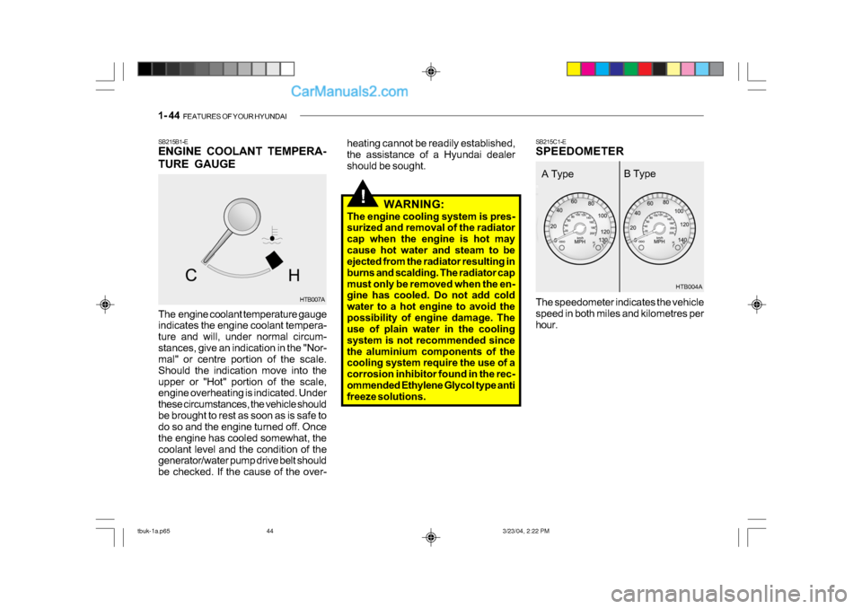
ENGINE COOLANT TEMPERA-
TURE GAUGE
The engine coolant temperature gauge
indicates the engine coolant tempera-
ture and will, under normal circum-
stances, give an indication in the "Nor-
mal" or centre portion of the scale.
Should the indication move into the
upper or "Hot" portion of the scale,
engine overheating is indicated. Under
these circumstances, the vehicle should
be brought to rest as soon as is safe to
do so and the engine turned off. Once
the engine has cooled somewhat, the
coolant level and the condition of the
generator/water pump drive belt should
be checked. If the cause of the over- SB215C1-E
SPEEDOMETER
HTB007A
heating cannot be readily established,
the assistance of a Hyundai dealer
should be sought.
HTB004A
The speedometer indicates the vehicle
speed in both miles and kilometres per
hour.
WARNING:
The engine cooling system is pres-
surized and removal of the radiator
cap when the engine is hot may
cause hot water and steam to be
ejected from the radiator resulting in
burns and scalding. The radiator cap
must only be removed when the en-
gine has cooled. Do not add cold
water to a hot engine to avoid the
possibility of engine damage. The
use of plain water in the cooling
system is not recommended since
the aluminium components of the
cooling system require the use of a
corrosion inhibitor found in the rec-
ommended Ethylene Glycol type anti
freeze solutions.
A Type B Type
tbuk-1a.p65
3/23/04, 2:22 PM
44
Page 367 of 445
3- 4 WHAT TO DO IN AN EMERGENCY
!
!
D030A01TB-EAT
IF THE ENGINE OVERHEATS
If the temperature gauge indicates
overheating:
1. Pull off the road and stop as soon as
it is safe to do so.
2. Place the gear selector lever in "P" (automatic), or neutral (manual
transaxle) and set the parking brake.
If the air conditioning is on, turn it off.
3. If coolant is running out under the car
or steam is coming out from under
the bonnet stop the engine. Do not
open the bonnet until the coolant has
stopped running or the steaming has
stopped. If there is no visible loss of
coolant and no steam, leave the
engine running and check to be sure
the engine cooling fan is operating.
If the fan is not running, turn the
engine off.
4. Check to see if the water pump drive belt is missing. If it is not missing,
check to see that it is tight. If the
drive belt seems to be satisfactory,
check for coolant leaking from the
radiator, hoses or under the car. (If
the air conditioning had been in use,
it is normal for cold water to be
draining from it). WARNING:
Whilst the engine is running, keep
hands and clothing away from mov-
ing parts such as the fan and drive
belts to prevent injury.
7. Switch ON the main beam
headlamps before carefully remov-
ing the jumper cables in the reverse
order of attachment. Once the
jumper cables have been removed,
switch "OFF" the main beam
headlamps.
CAUTION:
If the jump cable is incorrectly in-
stalled, damage to the vehicle elec-
trical system may occur, in particu-
lar the electronic components such
as the Fuel Injection system com-
puter and the Automatic transaxle
computer. The battery must never
be disconnected whilst the engine
is running.
!
WARNING (Diesel only):
Never work on injection system with
engine running or within 30 sec-
onds after shutting off engine. High
pressure pump, rail, injectors and
high pressure pipes are subject to
high pressure even after the engine
stopped. The fuel jet produced by
fuel leaks may cause serious in-
jury, if it touch the body. People
using pacemakers should not move
than 30cm closer to the ECU or
wiring harness within the engine
room while engine is running, since
the high currents in the Common
Rail system produce considerable
magnetic fields.
tbuk-3.p65 3/23/04, 4:24 PM
4
Page 368 of 445
WHAT TO DO IN AN EMERGENCY 3- 5
!
D040A01TB-EAT
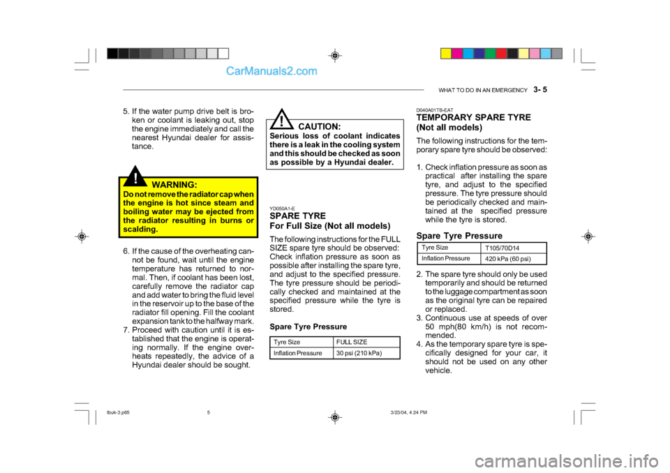
TEMPORARY SPARE TYRE
(Not all models)
The following instructions for the tem-
porary spare tyre should be observed:
1. Check inflation pressure as soon as
practical after installing the spare
tyre, and adjust to the specified
pressure. The tyre pressure should
be periodically checked and main-
tained at the specified pressure
while the tyre is stored.
6. If the cause of the overheating can- not be found, wait until the engine
temperature has returned to nor-
mal. Then, if coolant has been lost,
carefully remove the radiator cap
and add water to bring the fluid level
in the reservoir up to the base of the
radiator fill opening. Fill the coolant
expansion tank to the halfway mark.
7. Proceed with caution until it is es-
tablished that the engine is operat-
ing normally. If the engine over-
heats repeatedly, the advice of a
Hyundai dealer should be sought. WARNING:
Do not remove the radiator cap when
the engine is hot since steam and
boiling water may be ejected from
the radiator resulting in burns or
scalding.
Inflation Pressure
Tyre Size
T105/70D14
420 kPa (60 psi)
2. The spare tyre should only be used temporarily and should be returned
to the luggage compartment as soon
as the original tyre can be repaired
or replaced.
3. Continuous use at speeds of over 50 mph(80 km/h) is not recom-
mended.
4. As the temporary spare tyre is spe- cifically designed for your car, it
should not be used on any other
vehicle.
Spare Tyre Pressure
YD050A1-E
SPARE TYRE
For Full Size (Not all models)
The following instructions for the FULL
SIZE spare tyre should be observed:
Check inflation pressure as soon as
possible after installing the spare tyre,
and adjust to the specified pressure.
The tyre pressure should be periodi-
cally checked and maintained at the
specified pressure while the tyre is
stored.
Spare Tyre Pressure
Tyre Size
Inflation Pressure
FULL SIZE
30 psi (210 kPa)
5. If the water pump drive belt is bro-
ken or coolant is leaking out, stop
the engine immediately and call the
nearest Hyundai dealer for assis-
tance.
! CAUTION:
Serious loss of coolant indicates
there is a leak in the cooling system
and this should be checked as soon
as possible by a Hyundai dealer.
tbuk-3.p65 3/23/04, 4:24 PM
5
Page 403 of 445
6- 12 DO-IT-YOURSELF MAINTENANCE
!
HTB172
HTB171
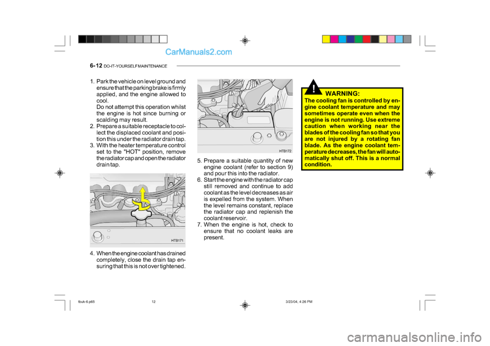
1. Park the vehicle on level ground and
ensure that the parking brake is firmly
applied, and the engine allowed to
cool.
Do not attempt this operation whilst
the engine is hot since burning or
scalding may result.
2. Prepare a suitable receptacle to col-
lect the displaced coolant and posi-
tion this under the radiator drain tap.
3. With the heater temperature control
set to the "HOT" position, remove
the radiator cap and open the radiator
drain tap. 5. Prepare a suitable quantity of new
engine coolant (refer to section 9)
and pour this into the radiator.
6. Start the engine with the radiator cap
still removed and continue to add
coolant as the level decreases as air
is expelled from the system. When
the level remains constant, replace
the radiator cap and replenish the
coolant reservoir.
7. When the engine is hot, check to ensure that no coolant leaks are
present.
4. When the engine coolant has drained completely, close the drain tap en-
suring that this is not over tightened. WARNING:
The cooling fan is controlled by en-
gine coolant temperature and may
sometimes operate even when the
engine is not running. Use extreme
caution when working near the
blades of the cooling fan so that you
are not injured by a rotating fan
blade. As the engine coolant tem-
perature decreases, the fan will auto-
matically shut off. This is a normal
condition.
tbuk-6.p65 3/23/04, 4:26 PM
12
Page 408 of 445
DO-IT-YOURSELF MAINTENANCE 6- 17
!
!
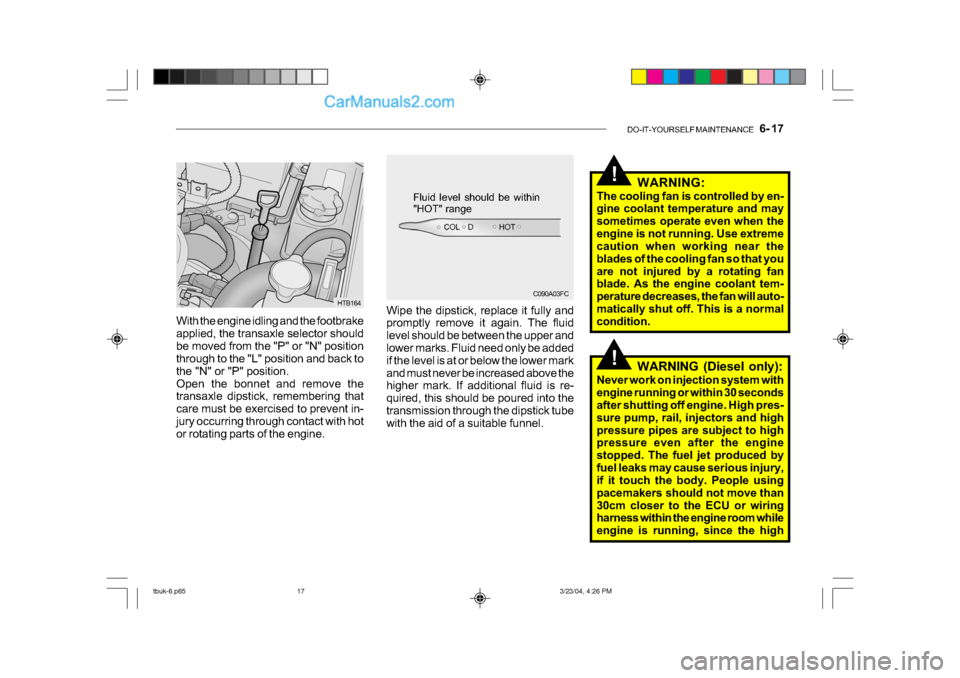
With the engine idling and the footbrake
applied, the transaxle selector should
be moved from the "P" or "N" position
through to the "L" position and back to
the "N" or "P" position.
Open the bonnet and remove the
transaxle dipstick, remembering that
care must be exercised to prevent in-
jury occurring through contact with hot
or rotating parts of the engine.
C090A03FC
Fluid level should be within
"HOT" range
HTB164 Wipe the dipstick, replace it fully and
promptly remove it again. The fluid
level should be between the upper and
lower marks. Fluid need only be added
if the level is at or below the lower mark
and must never be increased above the
higher mark. If additional fluid is re-
quired, this should be poured into the
transmission through the dipstick tube
with the aid of a suitable funnel. WARNING:
The cooling fan is controlled by en-
gine coolant temperature and may
sometimes operate even when the
engine is not running. Use extreme
caution when working near the
blades of the cooling fan so that you
are not injured by a rotating fan
blade. As the engine coolant tem-
perature decreases, the fan will auto-
matically shut off. This is a normal
condition.
WARNING (Diesel only):
Never work on injection system with
engine running or within 30 seconds
after shutting off engine. High pres-
sure pump, rail, injectors and high
pressure pipes are subject to high
pressure even after the engine
stopped. The fuel jet produced by
fuel leaks may cause serious injury,
if it touch the body. People using
pacemakers should not move than
30cm closer to the ECU or wiring
harness within the engine room while
engine is running, since the high
tbuk-6.p65 3/23/04, 4:26 PM
17
Page 416 of 445
DO-IT-YOURSELF MAINTENANCE 6- 25
!
!
o If battery electrolyte is spilled onto
skin or into eyes, the effected area
must be flushed with copious
amounts of water and medical assis-
tance sought.
o If battery electrolyte is ingested, copious amounts of water or milk
followed by an ant-acid (raw egg or
milk of magnesia) must be drunk.
Vomiting should not be induced and
medical assistance must be sought.
o Batteries must only be charged in well venti-lated areas from which
naked lights or sources of sparks are
excluded.
o Ensure that children, pets or other unauthorized persons are kept away
from batteries.
o Do not allow anything to bridge the positive (+) and negative (-) termi-
nals of the battery.
o Never invert the battery.
The battery fitted during production is of
the "Maintenance Free" type.
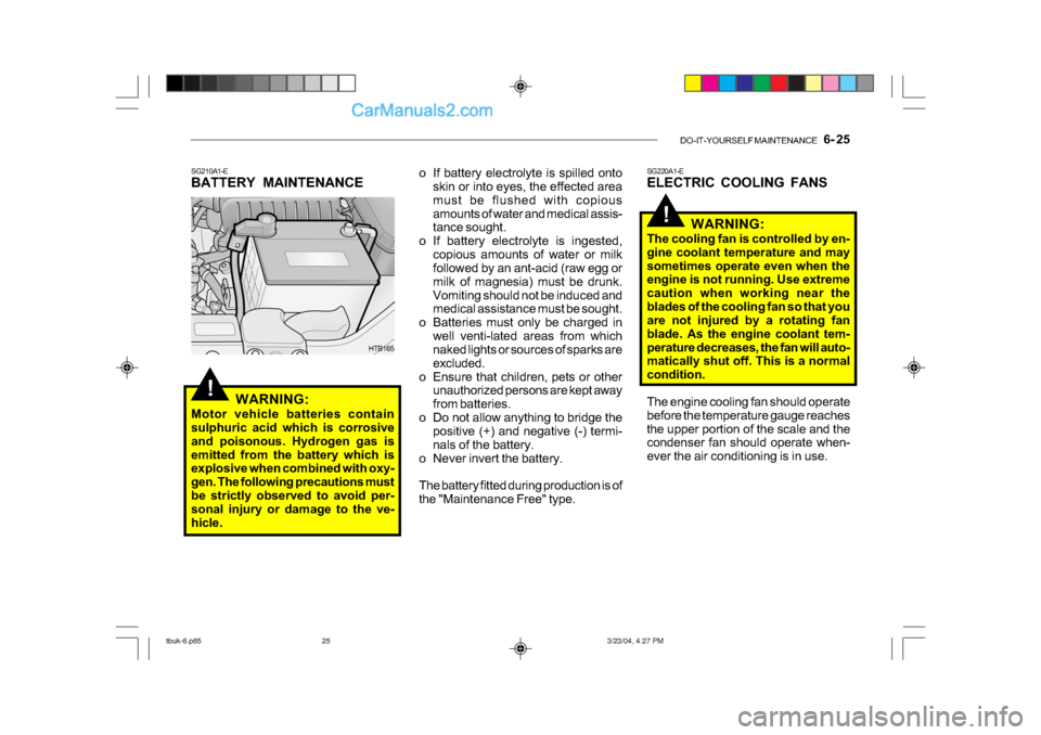
SG210A1-E
BATTERY MAINTENANCE
WARNING:
Motor vehicle batteries contain
sulphuric acid which is corrosive
and poisonous. Hydrogen gas is
emitted from the battery which is
explosive when combined with oxy-
gen. The following precautions must
be strictly observed to avoid per-
sonal injury or damage to the ve-
hicle.
HTB165 SG220A1-E
ELECTRIC COOLING FANS
WARNING:
The cooling fan is controlled by en-
gine coolant temperature and may
sometimes operate even when the
engine is not running. Use extreme
caution when working near the
blades of the cooling fan so that you
are not injured by a rotating fan
blade. As the engine coolant tem-
perature decreases, the fan will auto-
matically shut off. This is a normal
condition.
The engine cooling fan should operate
before the temperature gauge reaches
the upper portion of the scale and the
condenser fan should operate when-
ever the air conditioning is in use.
tbuk-6.p65 3/23/04, 4:27 PM
25
Page 428 of 445
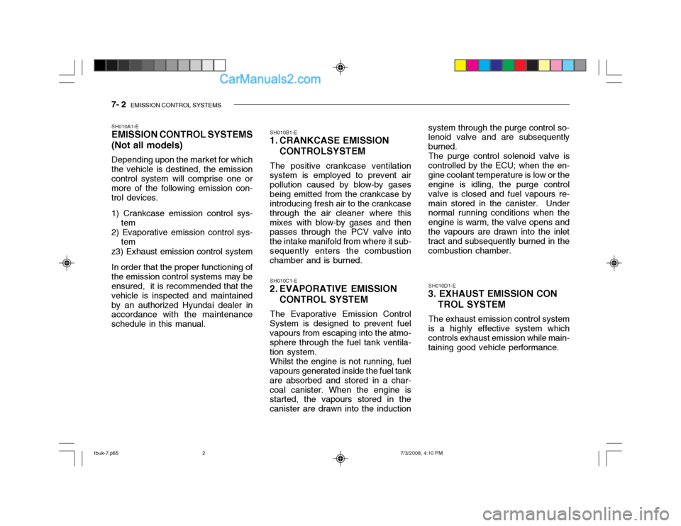
7- 2 EMISSION CONTROL SYSTEMS
SH010A1-E EMISSION CONTROL SYSTEMS (Not all models) Depending upon the market for which the vehicle is destined, the emissioncontrol system will comprise one or more of the following emission con- trol devices. 1) Crankcase emission control sys-
tem
2) Evaporative emission control sys-
tem
z3) Exhaust emission control systemIn order that the proper functioning of the emission control systems may be ensured, it is recommended that the vehicle is inspected and maintainedby an authorized Hyundai dealer in accordance with the maintenance schedule in this manual. SH010B1-E
1. CRANKCASE EMISSION
CONTROLSYSTEM
The positive crankcase ventilation
system is employed to prevent airpollution caused by blow-by gasesbeing emitted from the crankcase by introducing fresh air to the crankcase through the air cleaner where thismixes with blow-by gases and then passes through the PCV valve into the intake manifold from where it sub-sequently enters the combustion chamber and is burned.
SH010C1-E
2. EVAPORATIVE EMISSION
CONTROL SYSTEM
The Evaporative Emission Control
System is designed to prevent fuel vapours from escaping into the atmo- sphere through the fuel tank ventila- tion system.
Whilst the engine is not running, fuel
vapours generated inside the fuel tankare absorbed and stored in a char-coal canister. When the engine is started, the vapours stored in the canister are drawn into the induction SH010D1-E
3. EXHAUST EMISSION CON
TROL SYSTEM
The exhaust emission control system
is a highly effective system whichcontrols exhaust emission while main- taining good vehicle performance.
system through the purge control so-lenoid valve and are subsequently burned.
The purge control solenoid valve is
controlled by the ECU; when the en-gine coolant temperature is low or the engine is idling, the purge control valve is closed and fuel vapours re-main stored in the canister. Under normal running conditions when the engine is warm, the valve opens andthe vapours are drawn into the inlet tract and subsequently burned in the combustion chamber.
tbuk-7.p65 7/3/2008, 4:10 PM
2