flat tire Hyundai Getz 2004 User Guide
[x] Cancel search | Manufacturer: HYUNDAI, Model Year: 2004, Model line: Getz, Model: Hyundai Getz 2004Pages: 445, PDF Size: 12.16 MB
Page 165 of 445

WHAT TO DO IN AN EMERGENCY 3- 9
D060G01Y-AAT 6. Changing Wheels Loosen the wheel nuts and remove them with your fingers. Slide the wheel off the studs and lay it flat so it cannotroll away. To put the wheel on the hub, pick up the spare tire, line up the holes
HTB157
D060E01A-AAT 4. Put the Jack in Place The base of the jack should be placed on firm, level ground. The jack should be positioned as shown in the drawing.
D060F02E-AAT 5. Raising the Car After inserting a wrench bar into the wheel nut wrench, install the wrench bar into the jack as shown in the draw- ing. To raise the vehicle, turn the wheelnut wrench clockwise. As the jack be- gins to raise the vehicle, double check that it is properly positioned and willnot slip. If the jack is on soft ground or sand, place a board, brick, flat stone or other object under the base of the jackto keep it from sinking. Raise the car high enough so that the fully inflated spare tire can be installed.To do this, you will need more ground clearance than is required to remove the flat tire. HFC4022
Wrench bar
Wheel nut wrench
WARNING:
Do not get under the car when it is supported by the jack! This is very dangerous as the vehicle could falland cause serious injury or death. No one should stay in the car while the jack is being used.!
HTB228
Page 167 of 445

WHAT TO DO IN AN EMERGENCY 3- 11
Lower the car to the ground by turning the wheel nut wrench counterclock-wise. Then position the wrench as shown in the drawing and tighten the wheel nuts. Be sure the socket is seatedcompletely over the nut. Do not stand on the wrench handle or use an exten- sion pipe over the wrench handle.Go around the wheel tightening every other nut until they are all tight. Then double-check each nut for tightness.After changing wheels, have a techni- cian tighten the wheel nuts to their proper torque as soon as possible.
D060I01E-GAT 8. Lower Vehicle and Tighten Nuts
D060J01FC-GAT After Changing Wheels If you have a tire gauge, remove the valve cap and check the air pressure.If the pressure is lower than recom- mended, drive slowly to the nearest service station and inflate to the cor-rect pressure. If it is too high, adjust it until it is correct. Always reinstall the valve cap after checking or adjustingtire pressure. If the cap is not replaced, air may leak from the tire. If you lose a valve cap, buy another and install it assoon as possible.
Wheel nut tightening torque: Steel wheel & aluminium alloy wheel: 900-1,100 kg.cm (65-80 lb.ft)
HTB150
HTB151 After you have changed wheels, al- ways secure the flat tire in its place in the luggage room and return the jackand tools to their proper storage loca- tions.
D080A01TB-GAT IF YOUR CAR MUST BE TOWED
CAUTION:
Your car can be damaged if towed incorrectly! o OK FOR AUTOMATIC OR MANUAL
TRANSAXLE EQUIPPED VEHICLE
HTB207
!
Page 218 of 445
DO-IT-YOURSELF MAINTENANCE 6- 31
1. Remove the engine cover.
2. Disconnect the air intake hose from
air cleaner cover.
3. Loosen the drain plug at the bottom of the fuel filter.
4. Tighten the drain plug when water no longer comes out.
5. Check to be sure that the warning
lamp illuminates when the ignition key is turned to "ON", and that it goes off when the engine is started. If in doubt, consult your nearestauthorized HYUNDAI dealer.
NOTE: It is recommended that water accu- mulated in the fuel filter should beremoved by an authorized Hyundai dealer. G300B01FC
WARNING:
Be sure to carefully wipe away anywater drained out in this manner, because the fuel mixed in the watermight be ignited and result in a fire.
!
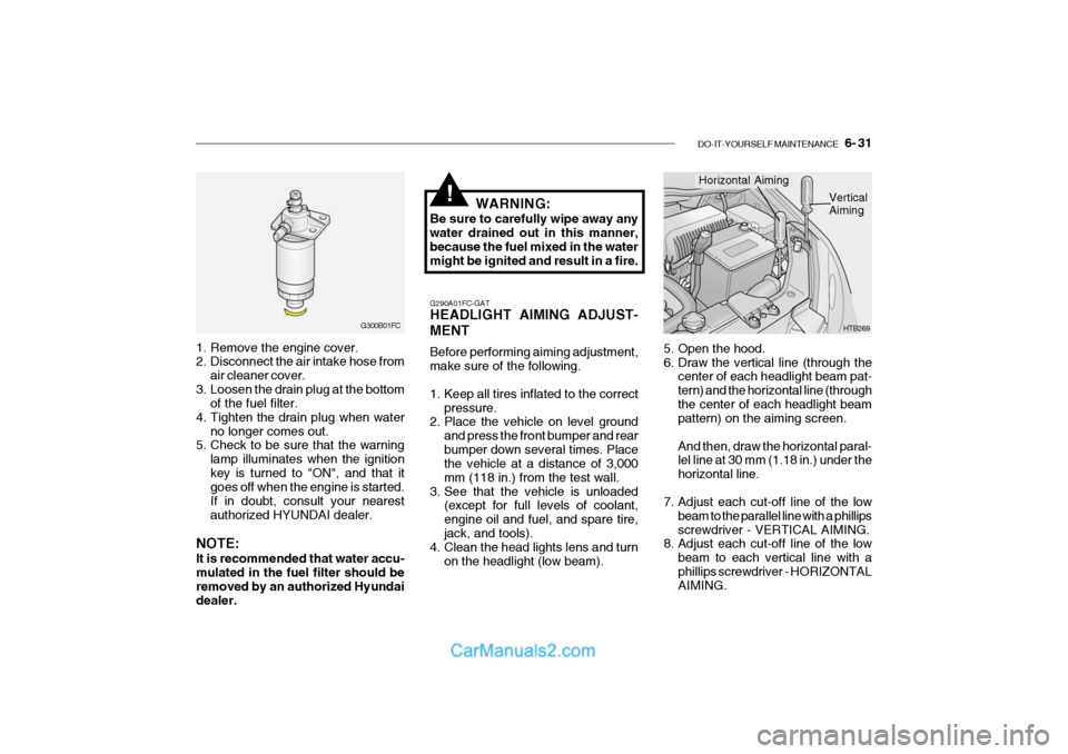
5. Open the hood.
6. Draw the vertical line (through the center of each headlight beam pat-tern) and the horizontal line (throughthe center of each headlight beam pattern) on the aiming screen. And then, draw the horizontal paral- lel line at 30 mm (1.18 in.) under the horizontal line.
7. Adjust each cut-off line of the low beam to the parallel line with a phillipsscrewdriver - VERTICAL AIMING.
8. Adjust each cut-off line of the low
beam to each vertical line with aphillips screwdriver - HORIZONTAL AIMING. HTB269
Horizontal Aiming
Vertical Aiming
G290A01FC-GAT HEADLIGHT AIMING ADJUST- MENT Before performing aiming adjustment, make sure of the following.
1. Keep all tires inflated to the correct pressure.
2. Place the vehicle on level ground
and press the front bumper and rear bumper down several times. Place the vehicle at a distance of 3,000 mm (118 in.) from the test wall.
3. See that the vehicle is unloaded (except for full levels of coolant,engine oil and fuel, and spare tire,jack, and tools).
4. Clean the head lights lens and turn
on the headlight (low beam).
Page 232 of 445

8. CONSUMER INFORMATION
Vehicle Identification Number (VIN) ............................................... 8-2
Engine number ............................................................................... 8-2
Recommended inflation pressures ................................................... 8-3
Snow tires ........................................................................................ 8-4
Tire chains ....................................................................................... 8-4
Tire rotation ...................................................................................... 8-5
Tire balancing ................................................................................... 8-5
Tire traction ...................................................................................... 8-5
When to replace tires ....................................................................... 8-5
Spare tire and tools .......................................................................... 8-6
8
Page 234 of 445
CONSUMER INFORMATION 8- 3
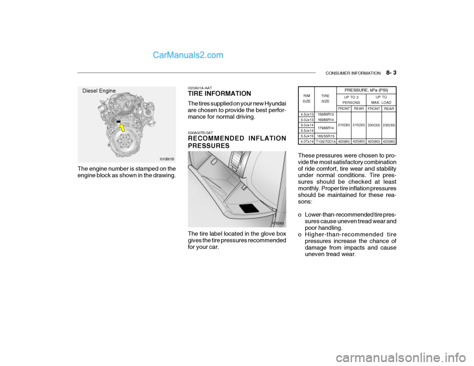
4.5Jx13 5.0Jx13 5.0Jx14 5.5Jx145.5Jx15
4.0Tx14 TIRE
SIZE
RIM
SIZE PRESSURE, kPa (PSI)
155/80R13165/65R14 175/65R14
185/55R15
T105/70D14 REAR
210(30) 420(60) FRONT
230(33) 420(60)
UP TO 2
PERSONS UP TO
MAX. LOAD
REAR
230(33)420(60)
FRONT 210(30) 420(60)
The engine number is stamped on the engine block as shown in the drawing. I020A01A-AAT TIRE INFORMATION The tires supplied on your new Hyundai are chosen to provide the best perfor-mance for normal driving. I030A03TB-GAT RECOMMENDED INFLATION PRESSURES The tire label located in the glove box gives the tire pressures recommended for your car.These pressures were chosen to pro- vide the most satisfactory combinationof ride comfort, tire wear and stability under normal conditions. Tire pres- sures should be checked at leastmonthly. Proper tire inflation pressures should be maintained for these rea- sons:
o Lower-than-recommended tire pres-
sures cause uneven tread wear and poor handling.
o Higher-than-recommended tire
pressures increase the chance ofdamage from impacts and cause uneven tread wear.
I010B01B
HTB263
Diesel Engine
Page 236 of 445

CONSUMER INFORMATION 8- 5
I070A01A-AAT TIRE BALANCING A tire that is out of balance may affect handling and tire wear. The tires onyour Hyundai were balanced before the car was delivered but may need balancing again during the years youown the car. Whenever a tire is dismounted for repair, it should be rebalanced beforebeing reinstalled on the car. I080A01A-AAT TIRE TRACTION Tire traction can be reduced if you drive on worn tires, tires that are im-properly inflated or on slippery road surfaces. Tires should be replaced when tread wear indicators appear. Toreduce the possibility of losing control, slow down whenever there is rain, snow or ice on the road. I090A01S-GAT WHEN TO REPLACE TIRES
I060A01FC-GAT TIRE ROTATION
Tires should be rotated every 10,000 km (6,000 miles). If you notice thattires are wearing unevenly between rotations, have the car checked by a Hyundai dealer so the cause may becorrected. After rotating, adjust the tire pressures and be sure to check wheel nut tight-ness.
HA1409Spare tire WARNING:
o Do not use the temporary spare tire for tire rotation.
o Do not mix bias-ply and radial-
ply tires under any circum- stances. This may cause danger- ous handling characteristics.
!
Wear indicator
1.6 mm (0.06 in.)
HGK248
Page 246 of 445

INDEX 10- 5
P Parking Brake ........................................................... 1-67
Power Steering Fluid Level ............................. ..........6-30
Power Windows ........................................................ 1-12
R Rear Seat .................................................................. 1-15
Rear Window Defroster Switch ................................ 1-56
SSeat Front ....................................................................... 1-13
Seatback Holder ....................................................... 1-70
Seat Pocket .............................................................. 1-70
Seat Warmer ............................................................. 1-19
Seat Belts
3-Point system ....................................................... 1-22
Adjustable height .................................................... 1-22
Adjusting your seat be lt .........................................1-23
Care of seat belts .................................................. 1-21
Precautions ............................................................ 1-20
Spark Plugs ............................................................... 6-15
Spectacle Case ......................................................... 1-63
Speedometer ............................................................. 1-49
Starting ........................................................................ 2-5
Steering Wheel Freeplay .................. ........................ 6-24
Steering Wheel Tilt Lever .............. ...........................1-74
Stereo Radio Operation (K210/K220, K240, H280, HMP280)
................................................. 1-86, 1-91, 1-96, 1-105Stereo Sound System
............................................... 1-84
Sun Visor .................................................................. 1-73
Sunroof ...................................................................... 1-60
T Tachometer ............................................................... 1-49
Tail gate .................................................................... 1-69
Theft-Alarm system ..................................................... 1-9
Tires Balancing .................................................................. 8-5
Chains ...................................................................... 8-4
If you have a flat tire ............................................... 3-6
Information ............................................................... 8-3
Pressure ................................................................... 8-3
Replacement ............................................................ 8-7
Rotation .................................................................... 8-5
Snow tires ................................................................ 8-4
Spare tire ................................................................. 3-5
Traction .................................................................... 8-5
Towing
A trailer (or vehicle) ............................................... 2-18
Emergency ............................................................. 3-13
If your car must be towed .....................................3-11
Trailer or Vehicle towing ........................................... 2-18
Transaxle Automatic ................................................................. 2-9
Automatic transaxle fluid checking ........................6-19
Manual ..................................................................... 2-7
Manual transaxle Oil checking............................... 6-18
Trip Computer ........................................................... 1-51
Trip Odometer ........................................................... 1-50
Page 293 of 445

FEATURES OF YOUR HYUNDAI 1- 35
!
B240C02L WARNING:
o Do not install a child restraint system in the front passenger
seat position.
A child restraint system must
never be placed in the front seat.
The infant or child could be se-
verely injured by an airbag de-
ployment in case of an accident.
o Extreme Hazard! Do not use a rear-
ward facing restraint on a seat
protected by an airbag in front of
it!
o Modification to SRS components or wiring, including the addition
of any kind of badges to the pad
covers or modifications to the
body structure, can adversely
affect SRS performance and lead
to possible injury.
o For cleaning the airbag pad cov-
ers, use only a soft, dry cloth or
one which has been moistened
with plain water. Solvents or
cleaners could adversely affect the
airbag covers and proper deploy-
ment of the system.
B240C02Y-GAT
SRS Care
The SRS is virtually maintenance-free
and there are no parts you can safely
service by yourself. The entire SRS
system must be inspected by an au-
thorized Hyundai dealer in 10 years
after the date that the vehicle was
manufactured.
Any work on the SRS system, such as
removing, installing, repairing, or any
work on the steering wheel must be
performed by a qualified Hyundai tech-
nician. Improper handling of the SRS
system may result in serious personal
injury.
o Do not place any objects (an um-
brella, bag, etc.) between the front
door and the front seat. Such ob-
jects may become dangerous pro-
jectiles and cause injury if the
supplemental side impact air bag
inflates.
o To prevent unexpected deploy- ment of the side air impact bag
that may result in personal injury,
avoid impact to the side airbag
sensor when the ignition key is
on.
tbuk-1a.p65 3/23/04, 2:22 PM
35
Page 418 of 445
DO-IT-YOURSELF MAINTENANCE 6- 27
!
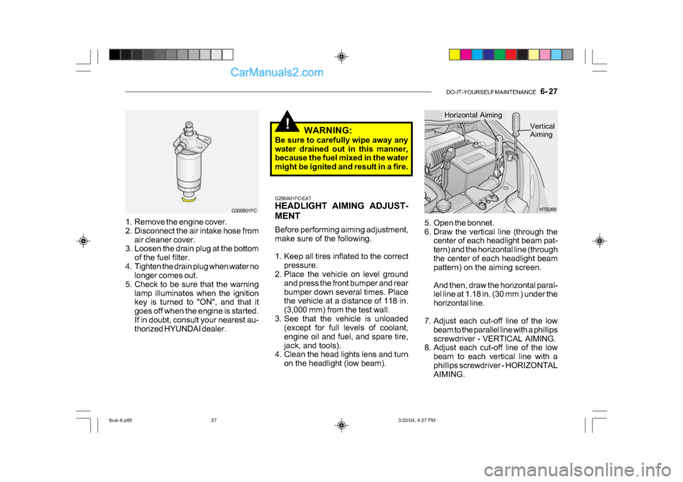
5. Open the bonnet.
6. Draw the vertical line (through the
center of each headlight beam pat-
tern) and the horizontal line (through
the center of each headlight beam
pattern) on the aiming screen.
And then, draw the horizontal paral-
lel line at 1.18 in. (30 mm ) under the
horizontal line.
7. Adjust each cut-off line of the low beam to the parallel line with a phillips
screwdriver - VERTICAL AIMING.
8. Adjust each cut-off line of the low
beam to each vertical line with a
phillips screwdriver - HORIZONTAL
AIMING. HTB269
Horizontal Aiming
Vertical
Aiming
G290A01FC-EAT
HEADLIGHT AIMING ADJUST-
MENT
Before performing aiming adjustment,
make sure of the following.
1. Keep all tires inflated to the correct pressure.
2. Place the vehicle on level ground
and press the front bumper and rear
bumper down several times. Place
the vehicle at a distance of 118 in.
(3,000 mm) from the test wall.
3. See that the vehicle is unloaded (except for full levels of coolant,
engine oil and fuel, and spare tire,
jack, and tools).
4. Clean the head lights lens and turn
on the headlight (low beam). WARNING:
Be sure to carefully wipe away any
water drained out in this manner,
because the fuel mixed in the water
might be ignited and result in a fire.
1. Remove the engine cover.
2. Disconnect the air intake hose from air cleaner cover.
3. Loosen the drain plug at the bottom
of the fuel filter.
4. Tighten the drain plug when water no longer comes out.
5. Check to be sure that the warning lamp illuminates when the ignition
key is turned to "ON", and that it
goes off when the engine is started.
If in doubt, consult your nearest au-
thorized HYUNDAI dealer.
G300B01FC
tbuk-6.p65 3/23/04, 4:27 PM
27