glove box Hyundai Getz 2004 Owner's Guide
[x] Cancel search | Manufacturer: HYUNDAI, Model Year: 2004, Model line: Getz, Model: Hyundai Getz 2004Pages: 445, PDF Size: 12.16 MB
Page 315 of 445

FEATURES OF YOUR HYUNDAI 1- 57
2. Insert the hexagonal head wrench
provided with the vehicle into the
socket. This wrench can be found in
the vehicle’s trunk or glove box.
3. Turn the wrench counterclockwise to open or clockwise to close the
sunroof. HGK033B460E01TB-GAT
Resetting the Sunroof System
If the battery has been recharged,
disconnected, if the sunroof is oper-
ated with the hexagonal head wrench
manually, or if the sunroof operation is
stopped by that ignition key is turned to
the "OFF" position while it is moving,
you may need to reset the sunroof.
To do this;
1. Turn the ignition switch "OFF".
2. With pressing "open" "up" button at
the same time, turn the ignition
switch "ON".
3. If the sunroof is set like this, the
sunroof is reset with tilting up/down
automatically once for all.
! CAUTION:
If the sunroof is not reset, it may not
be operated properly.
B460D01TB-AAT
Manual Operation of Sunroof
If the sunroof does not electrically op-
erate:
HGK032
1. Remove the cap located in the rear roof panel by using a coin or screw
driver.
tbuk-1a.p65 3/23/04, 2:22 PM
57
Page 317 of 445

FEATURES OF YOUR HYUNDAI 1- 59
!!WARNING:
To avoid the possibility of injury, the
glove box lid must be kept closed
whilst the vehicle is in motion.
o To open the glove box, pull the glove box release lever.
YB270A2-A
OUTSIDE REAR VIEW MIRROR
Manual Type (Not all models) The outside rear view mirrors are
equipped with a remote control for your
convenience. It is operated by the con-
trol lever in the bottom front corner of
the window.
Before driving away, always check that
your mirrors are positioned so you can
see directly behind you. When using
the mirror, always exercise caution when
attempting to judge the distance of
vehicles behind you.
HTB306
B500A01A-EAT
GLOVE BOX
HTB101-D
WARNING:
Do not keep objects such as sharp
or unsuitable things inside the spec-
tacle case. Such objects can be
thrown out in the event of a sudden
stop or an accident, possibly injur-
ing the passengers in the vehicle.
CAUTION:
If the mirror control is jammed with
ice, do not attempt to break it free
using the control handle or by ma-
nipulating the face of the mirror. Use
an approved spray de-icer (not radia-
tor antifreeze) to release the frozen
mechanism or move the vehicle to a
warm place and allow the ice to melt.
!
tbuk-1a.p65 3/23/04, 2:22 PM
59
Page 337 of 445
FEATURES OF YOUR HYUNDAI 1- 79
!
B760A01Y
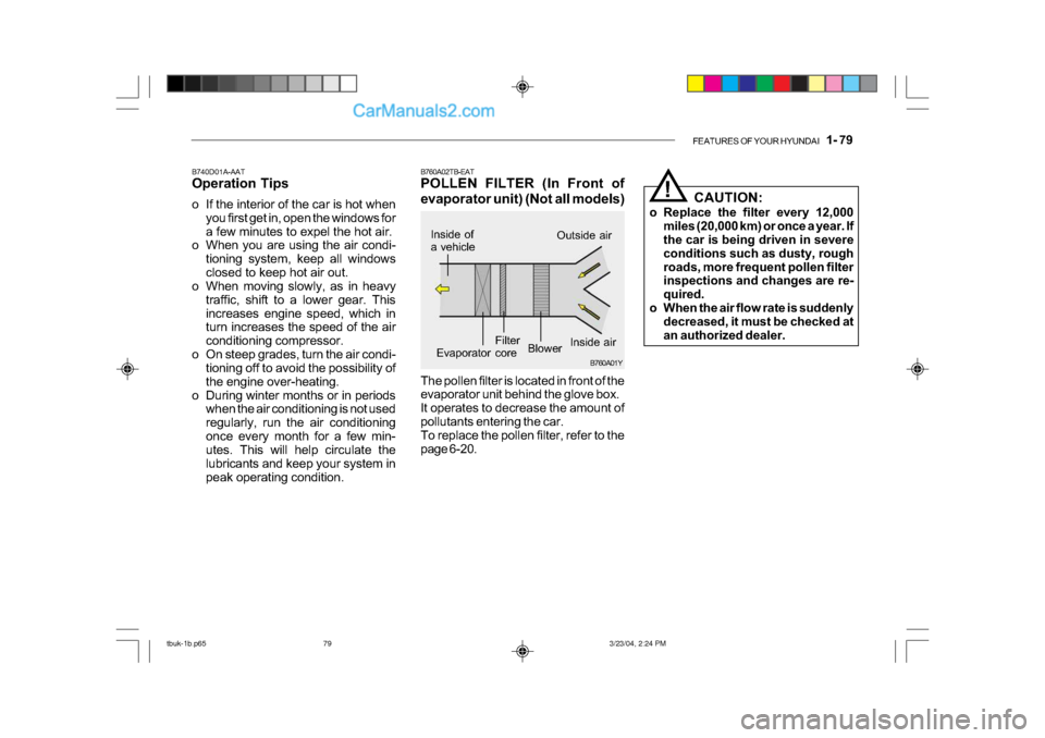
The pollen filter is located in front of the
evaporator unit behind the glove box.
It operates to decrease the amount of
pollutants entering the car.
To replace the pollen filter, refer to the
page 6-20.
B760A02TB-EAT
POLLEN FILTER (In Front of
evaporator unit) (Not all models)
B740D01A-AAT
Operation Tips
o If the interior of the car is hot when
you first get in, open the windows for
a few minutes to expel the hot air.
o When you are using the air condi-
tioning system, keep all windows
closed to keep hot air out.
o When moving slowly, as in heavy
traffic, shift to a lower gear. This
increases engine speed, which in
turn increases the speed of the air
conditioning compressor.
o On steep grades, turn the air condi- tioning off to avoid the possibility of
the engine over-heating.
o During winter months or in periods when the air conditioning is not used
regularly, run the air conditioning
once every month for a few min-
utes. This will help circulate the
lubricants and keep your system in
peak operating condition. Inside of
a vehicle
Evaporator core
Filter
BlowerOutside air
Inside air CAUTION:
o Replace the filter every 12,000 miles (20,000 km) or once a year. If
the car is being driven in severe
conditions such as dusty, rough
roads, more frequent pollen filter
inspections and changes are re-
quired.
o When the air flow rate is suddenly decreased, it must be checked at
an authorized dealer.
tbuk-1b.p65 3/23/04, 2:24 PM
79
Page 411 of 445
6- 20 DO-IT-YOURSELF MAINTENANCE
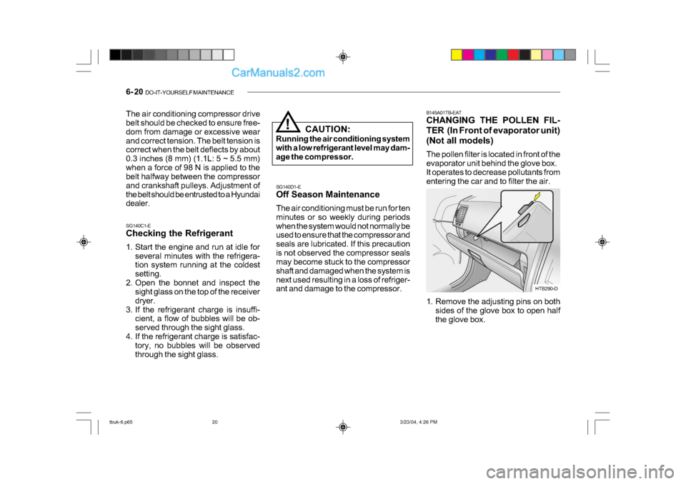
B145A01TB-EAT
CHANGING THE POLLEN FIL-
TER (In Front of evaporator unit)
(Not all models)
The pollen filter is located in front of the
evaporator unit behind the glove box.
It operates to decrease pollutants from
entering the car and to filter the air.
1. Remove the adjusting pins on both
sides of the glove box to open half
the glove box.
HTB290-D
SG140D1-E
Off Season Maintenance
The air conditioning must be run for ten
minutes or so weekly during periods
when the system would not normally be
used to ensure that the compressor and
seals are lubricated. If this precaution
is not observed the compressor seals
may become stuck to the compressor
shaft and damaged when the system is
next used resulting in a loss of refriger-
ant and damage to the compressor.
SG140C1-E
Checking the Refrigerant
1. Start the engine and run at idle for
several minutes with the refrigera-
tion system running at the coldest
setting.
2. Open the bonnet and inspect the sight glass on the top of the receiver
dryer.
3. If the refrigerant charge is insuffi- cient, a flow of bubbles will be ob-
served through the sight glass.
4. If the refrigerant charge is satisfac- tory, no bubbles will be observed
through the sight glass. CAUTION:
Running the air conditioning system
with a low refrigerant level may dam-
age the compressor.
!
The air conditioning compressor drive
belt should be checked to ensure free-
dom from damage or excessive wear
and correct tension. The belt tension is
correct when the belt deflects by about
0.3 inches (8 mm) (1.1L: 5 ~ 5.5 mm)
when a force of 98 N is applied to the
belt halfway between the compressor
and crankshaft pulleys. Adjustment of
the belt should be entrusted to a Hyundai
dealer.
tbuk-6.p65
3/23/04, 4:26 PM
20
Page 433 of 445
CONSUMER INFORMATION 8- 3
4.5Jx13
5.0Jx13
5.0Jx14
5.5Jx14
5.5Jx15
4.0Tx14 TYRE
SIZE
RIM
SIZE PRESSURE, kPa (PSI)
15/80R13
165/65R14
175/65R14
185/55R15
T105/70D14 REAR
210(30)
420(60) FRONT
230(33)
420(60)
UP TO 2
PERSONS UP TO
MAX. LOAD
REAR
230(33)
420(60)
FRONT
210(30)
420(60)
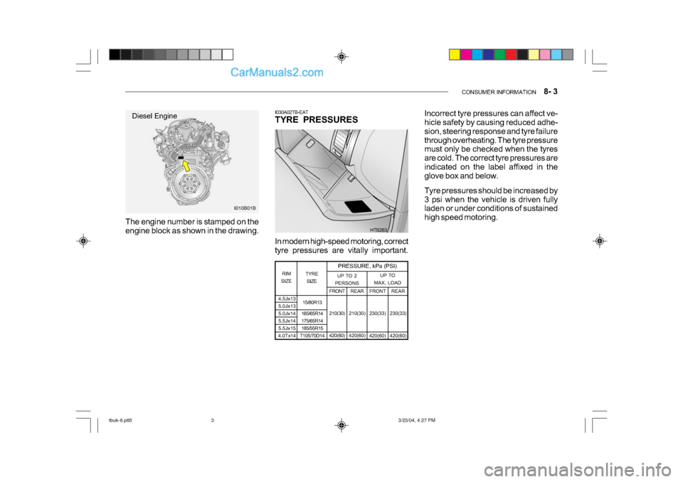
The engine number is stamped on the
engine block as shown in the drawing. I030A02TB-EAT
TYRE PRESSURES
In modern high-speed motoring, correct
tyre pressures are vitally important.
I010B01B
HTB263
Diesel EngineIncorrect tyre pressures can affect ve-
hicle safety by causing reduced adhe-
sion, steering response and tyre failure
through overheating. The tyre pressure
must only be checked when the tyres
are cold. The correct tyre pressures are
indicated on the label affixed in the
glove box and below.
Tyre pressures should be increased by
3 psi when the vehicle is driven fully
laden or under conditions of sustained
high speed motoring.
tbuk-8.p65 3/23/04, 4:27 PM
3
Page 443 of 445
INDEX 10- 3
ENGINE OIL REPLENISHMENT ................................ 6-8
ENGINE OIL ................................................... ............ 6-6
F
FRONT ASHTRAY ... ................................................. 1-54
FRONT SEAT ................................................... ........1-11
FRONT FOG LIGHT SWITCH.................................. 1-52
FUEL ECONOMY ........ ............................................... 2-7
FUEL GAUGE ................................................... ........1-43
FUEL RECOMMENDATIONS ..................................... 1-1
FUSE PANEL DESCRI PTION.................................. 6-34
FUSIBLE LINKS ................................................... .....6-24
G
GLOVE BOX ................................................... ..........1-59
H
HAZARD WARNING SYSTEM .................................1-51
HEADLIGHT AIMING ADJUSTEMENT ....................6-27
HEADLIGHT BULB ................................................... 6-28
HEADLIGHT LEVELING DEVICE SYSTEM.............1-55
HEAD RESTRAINT ADJUSTMENT.......................... 1-14
HEATED REAR WINDOW ........................................1-52
HEATING AND COOLING CONTROL .....................1-71
HEIGHT ADJUSTABLE FRONT SEAT SHOULDER BELT ................................................ 1-19
HORN ................................................... .....................1-70
HOW TO USE LUGGAGE ROO M ............................1-66I
IF THE ENGINE CANNOT BE CRANKED
................. 3-2
IF THE ENGINE OVERHEATS ................................... 3-4
IF THE ENGINE WILL NOT START ........................... 3-2
IF THE EVENT OF A PUNCTURE ............................. 3-6
IMMOBILISER SYSTEM ............................................. 1-4
INDIVIDUAL CI RCUIT FUSES ................................. 6-24
INSTRUMENT CLUSTER AND INDICATORS .........1-37
INTERIOR LIGHT ................................................... ..1-58
INTERIOR REAR VIEW MIRROR ............................1-61
J
JUMP STARTING ..... .................................................. 3 -3
K
KEY POSITIONS ................................................... ..... 2-3
L
LIGHTING SWITCH .................................................. 1-49
LUGGAGE BOARD ...................................... .............1-67
LUGGAGE NET ................................................... .....1-67
LUGGAGE ROOM ................................................... .1-66
LUGGAGE UNDER TRAY........................................ 1-66
LUMBAR SUPPORT ADJUSTMENT........................ 1-13
tbuk-10.p65 3/23/04, 4:31 PM
3