warning light Hyundai Getz 2004 Repair Manual
[x] Cancel search | Manufacturer: HYUNDAI, Model Year: 2004, Model line: Getz, Model: Hyundai Getz 2004Pages: 445, PDF Size: 12.16 MB
Page 365 of 445
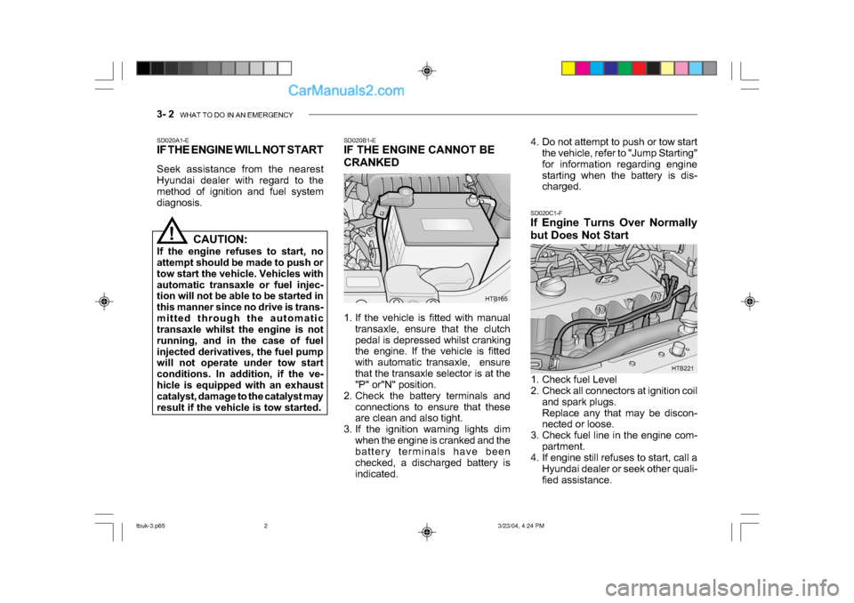
3- 2 WHAT TO DO IN AN EMERGENCY
HTB165
SD020B1-E
IF THE ENGINE CANNOT BE
CRANKED
1. If the vehicle is fitted with manual
transaxle, ensure that the clutch
pedal is depressed whilst cranking
the engine. If the vehicle is fitted
with automatic transaxle, ensure
that the transaxle selector is at the
"P" or"N" position.
2. Check the battery terminals and
connections to ensure that these
are clean and also tight.
3. If the ignition warning lights dim
when the engine is cranked and the
battery terminals have been
checked, a discharged battery is
indicated. SD020C1-F
If Engine Turns Over Normally
but Does Not Start
SD020A1-E
IF THE ENGINE WILL NOT START
Seek assistance from the nearest
Hyundai dealer with regard to the
method of ignition and fuel system
diagnosis.
!
HTB221
CAUTION:
If the engine refuses to start, no
attempt should be made to push or
tow start the vehicle. Vehicles with
automatic transaxle or fuel injec-
tion will not be able to be started in
this manner since no drive is trans-
mitted through the automatic
transaxle whilst the engine is not
running, and in the case of fuel
injected derivatives, the fuel pump
will not operate under tow start
conditions. In addition, if the ve-
hicle is equipped with an exhaust
catalyst, damage to the catalyst may
result if the vehicle is tow started. 4. Do not attempt to push or tow start
the vehicle, refer to "Jump Starting"
for information regarding engine
starting when the battery is dis-
charged.
1. Check fuel Level
2. Check all connectors at ignition coil and spark plugs.
Replace any that may be discon-
nected or loose.
3. Check fuel line in the engine com- partment.
4. If engine still refuses to start, call a
Hyundai dealer or seek other quali-
fied assistance.
tbuk-3.p65 3/23/04, 4:24 PM
2
Page 366 of 445
WHAT TO DO IN AN EMERGENCY 3- 3
!
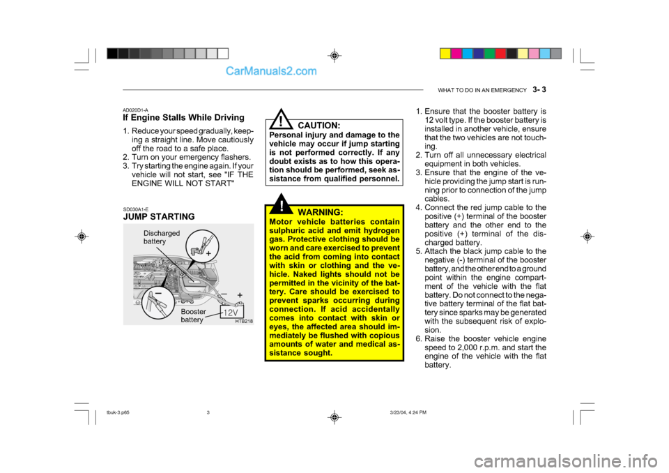
HTB218
Discharged
battery
Booster
battery
CAUTION:
Personal injury and damage to the
vehicle may occur if jump starting
is not performed correctly. If any
doubt exists as to how this opera-
tion should be performed, seek as-
sistance from qualified personnel.
SD030A1-E
JUMP STARTING
AD020D1-A
If Engine Stalls While Driving
1. Reduce your speed gradually, keep-
ing a straight line. Move cautiously
off the road to a safe place.
2. Turn on your emergency flashers.
3. Try starting the engine again. If your
vehicle will not start, see "IF THE
ENGINE WILL NOT START"!
WARNING:
Motor vehicle batteries contain
sulphuric acid and emit hydrogen
gas. Protective clothing should be
worn and care exercised to prevent
the acid from coming into contact
with skin or clothing and the ve-
hicle. Naked lights should not be
permitted in the vicinity of the bat-
tery. Care should be exercised to
prevent sparks occurring during
connection. If acid accidentally
comes into contact with skin or
eyes, the affected area should im-
mediately be flushed with copious
amounts of water and medical as-
sistance sought. 1. Ensure that the booster battery is
12 volt type. If the booster battery is
installed in another vehicle, ensure
that the two vehicles are not touch-
ing.
2. Turn off all unnecessary electrical equipment in both vehicles.
3. Ensure that the engine of the ve-
hicle providing the jump start is run-
ning prior to connection of the jump
cables.
4. Connect the red jump cable to the positive (+) terminal of the booster
battery and the other end to the
positive (+) terminal of the dis-
charged battery.
5. Attach the black jump cable to the
negative (-) terminal of the booster
battery, and the other end to a ground
point within the engine compart-
ment of the vehicle with the flat
battery. Do not connect to the nega-
tive battery terminal of the flat bat-
tery since sparks may be generated
with the subsequent risk of explo-
sion.
6. Raise the booster vehicle engine speed to 2,000 r.p.m. and start the
engine of the vehicle with the flat
battery.
tbuk-3.p65 3/23/04, 4:24 PM
3
Page 397 of 445
6- 6 DO-IT-YOURSELF MAINTENANCE
SG020B1-E
DAILY OPERATING CHECKS
The following items should be checked
on a daily basis or whenever the vehicle
is refuelled, whichever occurs sooner.
o Engine oil level.
o Engine coolant level.
o Power steering fluid level.
o Brake fluid level.
o Windscreen washer fluid level.
o Battery condition.
o Tyre condition and pressures.
o Operation and cleanliness of all light-
ing equipment.
o Windscreen wiper and washer opera- tion.
o Horn operation.
o Warning light operation.
o Adjustment and cleanliness of mir- rors.
o Seat and seat belt adjustment and operation.
o Fluid leakage.
The vehicle must not be driven if the
daily operating checks indicate that
any item of equipment related to the
safety or roadworthiness of the vehicle
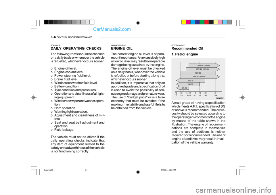
is not functioning correctly. G030B02A-EAT
Recommended Oil
1. Petrol engine
A multi grade oil having a specification
which meets A.P.I. specification of SG
or above is recommended. The oil vis-
cosity should be selected according to
the operating environment of the engine
by means of the table shown in the
illustration. The engine oil recommen-
dations are complete in themselves
and the use of additives is neither
required nor recommended. The use of
engine oil additives may result in invali-
dation of the vehicle warranty.
G030A01FC-EAT
ENGINE OIL
The correct engine oil level is of para-
mount importance. An excessively high
or low oil level may result in irreparable
damage being sustained by the engine.
The engine oil level must be checked
on a daily basis, whenever the vehicle
is refuelled or before starting a long trip,
whichever occurs sooner.
In addition, it is imperative that only an
approved grade and specification of oil
is used to avoid the possibility of seri-
ous engine damage and premature wear.
The use of "budget price" oil is a false
economy that must be avoided if the
maximum reliability and useful life is to
be obtained from the vehicle.
G030B01L
tbuk-6.p65
3/23/04, 4:26 PM
6
Page 415 of 445
6- 24 DO-IT-YOURSELF MAINTENANCE
!
!
SG200A1-E
FUSIBLE LINKS
The fusible link prevents damage to the
wiring harness in the event of an elec-
trical system malfunction. Failure of a
fusiblelink is indicative of a serious
overload condition having occurred and
therefore the electrical system should
be checked by a Hyundai dealer before
a replacement link is fitted.
WARNING:
Under no circumstances should a
fusible link be replaced with any-
thing other than a new link of the
same rating. The use of higher rated
links or other means of connecting
the circuit will create a potential fire
hazard.G200B01E-EAT
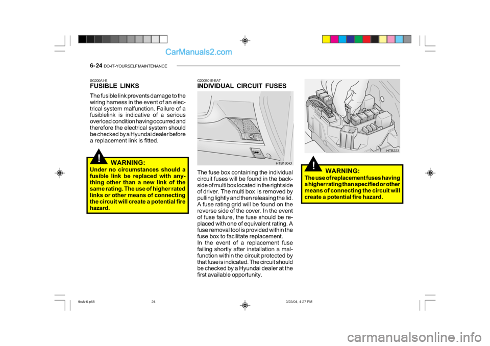
INDIVIDUAL CIRCUIT FUSES
The fuse box containing the individual
circuit fuses will be found in the back-
side of multi box located in the right side
of driver. The multi box is removed by
pulling lightly and then releasing the lid.
A fuse rating grid will be found on the
reverse side of the cover. In the event
of fuse failure, the fuse should be re-
placed with one of equivalent rating. A
fuse removal tool is provided within the
fuse box to facilitate replacement.
In the event of a replacement fuse
failing shortly after installation a mal-
function within the circuit protected by
that fuse is indicated. The circuit should
be checked by a Hyundai dealer at the
first available opportunity. HTB180-D
HTB223
WARNING:
The use of replacement fuses having
a higher rating than specified or other
means of connecting the circuit will
create a potential fire hazard.
tbuk-6.p65 3/23/04, 4:27 PM
24
Page 416 of 445
DO-IT-YOURSELF MAINTENANCE 6- 25
!
!
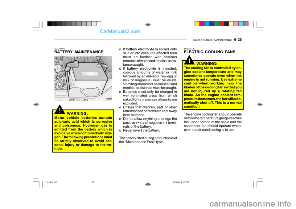
o If battery electrolyte is spilled onto
skin or into eyes, the effected area
must be flushed with copious
amounts of water and medical assis-
tance sought.
o If battery electrolyte is ingested, copious amounts of water or milk
followed by an ant-acid (raw egg or
milk of magnesia) must be drunk.
Vomiting should not be induced and
medical assistance must be sought.
o Batteries must only be charged in well venti-lated areas from which
naked lights or sources of sparks are
excluded.
o Ensure that children, pets or other unauthorized persons are kept away
from batteries.
o Do not allow anything to bridge the positive (+) and negative (-) termi-
nals of the battery.
o Never invert the battery.
The battery fitted during production is of
the "Maintenance Free" type.
SG210A1-E
BATTERY MAINTENANCE
WARNING:
Motor vehicle batteries contain
sulphuric acid which is corrosive
and poisonous. Hydrogen gas is
emitted from the battery which is
explosive when combined with oxy-
gen. The following precautions must
be strictly observed to avoid per-
sonal injury or damage to the ve-
hicle.
HTB165 SG220A1-E
ELECTRIC COOLING FANS
WARNING:
The cooling fan is controlled by en-
gine coolant temperature and may
sometimes operate even when the
engine is not running. Use extreme
caution when working near the
blades of the cooling fan so that you
are not injured by a rotating fan
blade. As the engine coolant tem-
perature decreases, the fan will auto-
matically shut off. This is a normal
condition.
The engine cooling fan should operate
before the temperature gauge reaches
the upper portion of the scale and the
condenser fan should operate when-
ever the air conditioning is in use.
tbuk-6.p65 3/23/04, 4:27 PM
25
Page 418 of 445
DO-IT-YOURSELF MAINTENANCE 6- 27
!
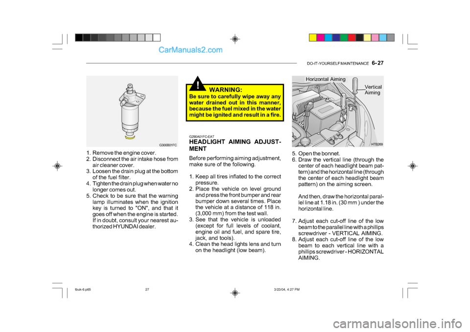
5. Open the bonnet.
6. Draw the vertical line (through the
center of each headlight beam pat-
tern) and the horizontal line (through
the center of each headlight beam
pattern) on the aiming screen.
And then, draw the horizontal paral-
lel line at 1.18 in. (30 mm ) under the
horizontal line.
7. Adjust each cut-off line of the low beam to the parallel line with a phillips
screwdriver - VERTICAL AIMING.
8. Adjust each cut-off line of the low
beam to each vertical line with a
phillips screwdriver - HORIZONTAL
AIMING. HTB269
Horizontal Aiming
Vertical
Aiming
G290A01FC-EAT
HEADLIGHT AIMING ADJUST-
MENT
Before performing aiming adjustment,
make sure of the following.
1. Keep all tires inflated to the correct pressure.
2. Place the vehicle on level ground
and press the front bumper and rear
bumper down several times. Place
the vehicle at a distance of 118 in.
(3,000 mm) from the test wall.
3. See that the vehicle is unloaded (except for full levels of coolant,
engine oil and fuel, and spare tire,
jack, and tools).
4. Clean the head lights lens and turn
on the headlight (low beam). WARNING:
Be sure to carefully wipe away any
water drained out in this manner,
because the fuel mixed in the water
might be ignited and result in a fire.
1. Remove the engine cover.
2. Disconnect the air intake hose from air cleaner cover.
3. Loosen the drain plug at the bottom
of the fuel filter.
4. Tighten the drain plug when water no longer comes out.
5. Check to be sure that the warning lamp illuminates when the ignition
key is turned to "ON", and that it
goes off when the engine is started.
If in doubt, consult your nearest au-
thorized HYUNDAI dealer.
G300B01FC
tbuk-6.p65 3/23/04, 4:27 PM
27
Page 420 of 445
DO-IT-YOURSELF MAINTENANCE 6- 29
!
HTB183
HTB268HTB184
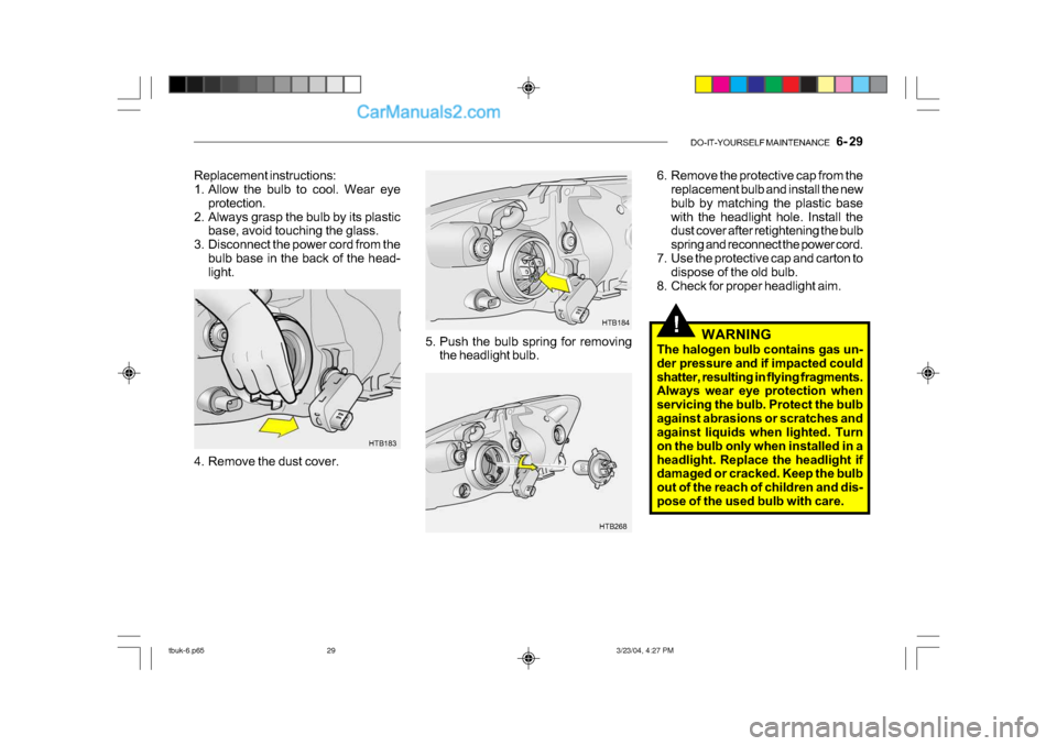
Replacement instructions:
1. Allow the bulb to cool. Wear eye
protection.
2. Always grasp the bulb by its plastic base, avoid touching the glass.
3. Disconnect the power cord from the bulb base in the back of the head-
light.
4. Remove the dust cover. 5. Push the bulb spring for removing
the headlight bulb. 6. Remove the protective cap from the
replacement bulb and install the new
bulb by matching the plastic base
with the headlight hole. Install the
dust cover after retightening the bulb
spring and reconnect the power cord.
7. Use the protective cap and carton to dispose of the old bulb.
8. Check for proper headlight aim.
WARNING
The halogen bulb contains gas un-
der pressure and if impacted could
shatter, resulting in flying fragments.
Always wear eye protection when
servicing the bulb. Protect the bulb
against abrasions or scratches and
against liquids when lighted. Turn
on the bulb only when installed in a
headlight. Replace the headlight if
damaged or cracked. Keep the bulb
out of the reach of children and dis-
pose of the used bulb with care.
tbuk-6.p65 3/23/04, 4:27 PM
29
Page 426 of 445
DO-IT-YOURSELF MAINTENANCE 6- 35
G200E01TB-GAT
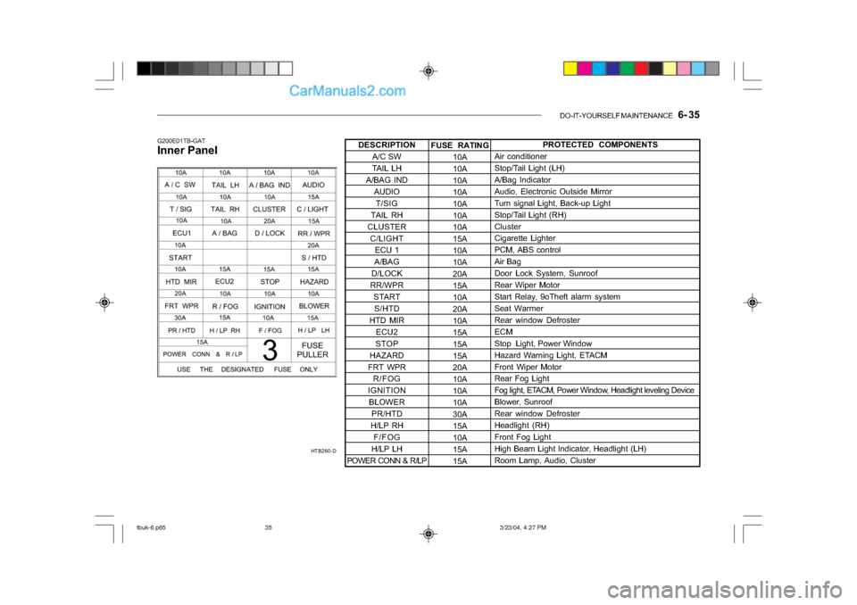
Inner Panel
HTB260-DFUSE RATING10A
10A
10A
10A
10A
10A
10A
15A
10A
10A
20A
15A
10A
20A
10A
15A
15A
15A
20A
10A
10A
10A
30A
15A
10A
15A
15APROTECTED COMPONENTS
Air conditioner
Stop/Tail Light (LH)
A/Bag Indicator
Audio, Electronic Outside Mirror
Turn signal Light, Back-up Light
Stop/Tail Light (RH)
Cluster
Cigarette Lighter
PCM, ABS control
Air Bag
Door Lock System, Sunroof
Rear Wiper Motor
Start Relay, 9oTheft alarm system
Seat Warmer
Rear window Defroster
ECM
Stop Light, Power Window
Hazard Warning Light, ETACM
Front Wiper Motor
Rear Fog Light
Fog light, ETACM, Power Window, Headlight leveling Device
Blower, Sunroof
Rear window Defroster
Headlight (RH)
Front Fog Light
High Beam Light Indicator, Headlight (LH)
Room Lamp, Audio, Cluster
DESCRIPTION
A/C SW
TAIL LH
A/BAG IND
AUDIO
T/SIG
TAIL RH
CLUSTER C/LIGHT ECU 1
A/BAG
D/LOCK
RR/WPR STARTS/HTD
HTD MIR ECU2
STOP
HAZARD
FRT WPR R/FOG
IGNITION BLOWER PR/HTD
H/LP RH F/FOG
H/LP LH
POWER CONN & R/LP
tbuk-6.p65 3/23/04, 4:27 PM
35
Page 443 of 445
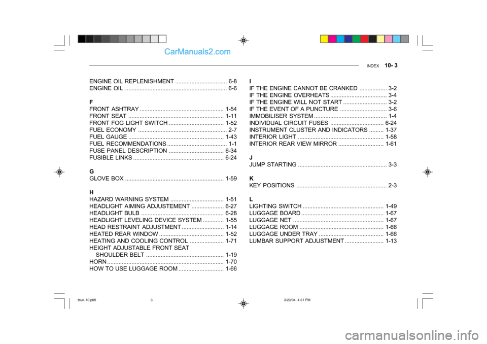
INDEX 10- 3
ENGINE OIL REPLENISHMENT ................................ 6-8
ENGINE OIL ................................................... ............ 6-6
F
FRONT ASHTRAY ... ................................................. 1-54
FRONT SEAT ................................................... ........1-11
FRONT FOG LIGHT SWITCH.................................. 1-52
FUEL ECONOMY ........ ............................................... 2-7
FUEL GAUGE ................................................... ........1-43
FUEL RECOMMENDATIONS ..................................... 1-1
FUSE PANEL DESCRI PTION.................................. 6-34
FUSIBLE LINKS ................................................... .....6-24
G
GLOVE BOX ................................................... ..........1-59
H
HAZARD WARNING SYSTEM .................................1-51
HEADLIGHT AIMING ADJUSTEMENT ....................6-27
HEADLIGHT BULB ................................................... 6-28
HEADLIGHT LEVELING DEVICE SYSTEM.............1-55
HEAD RESTRAINT ADJUSTMENT.......................... 1-14
HEATED REAR WINDOW ........................................1-52
HEATING AND COOLING CONTROL .....................1-71
HEIGHT ADJUSTABLE FRONT SEAT SHOULDER BELT ................................................ 1-19
HORN ................................................... .....................1-70
HOW TO USE LUGGAGE ROO M ............................1-66I
IF THE ENGINE CANNOT BE CRANKED
................. 3-2
IF THE ENGINE OVERHEATS ................................... 3-4
IF THE ENGINE WILL NOT START ........................... 3-2
IF THE EVENT OF A PUNCTURE ............................. 3-6
IMMOBILISER SYSTEM ............................................. 1-4
INDIVIDUAL CI RCUIT FUSES ................................. 6-24
INSTRUMENT CLUSTER AND INDICATORS .........1-37
INTERIOR LIGHT ................................................... ..1-58
INTERIOR REAR VIEW MIRROR ............................1-61
J
JUMP STARTING ..... .................................................. 3 -3
K
KEY POSITIONS ................................................... ..... 2-3
L
LIGHTING SWITCH .................................................. 1-49
LUGGAGE BOARD ...................................... .............1-67
LUGGAGE NET ................................................... .....1-67
LUGGAGE ROOM ................................................... .1-66
LUGGAGE UNDER TRAY........................................ 1-66
LUMBAR SUPPORT ADJUSTMENT........................ 1-13
tbuk-10.p65 3/23/04, 4:31 PM
3
Page 444 of 445
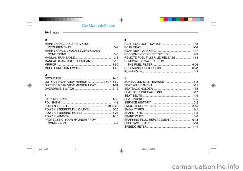
10- 4 INDEX
M
MAINTENANCE AND SERVICING
REQUIREMENTS ................................................... 5-2
MAINTENANCE UNDER SEVERE USAGE CONDITIONS ......................................... ................. 5-6
MANUAL TRANSAXLE ............................................... 2-8
MANUAL TRANSAXLE L UBRICANT........................ 6-15
MIRROR ................................................... .................1-59
MULTI FUNCTION SWITCH.................................... 1-48
O
ODOMETER ........................................... ..................1-45
OUTSIDE REAR VIEW MIRROR .................. 1-59 ~ 1-60
OUTSIDE REAR VIEW MIRROR HEAT ...................1-61
OVERDRIVE SWITCH .............................................. 2-12
P
PARKING BRAKE ................................................... ..1-62
POLISHING .......................................... ....................... 4-3
POLLEN FILTER .............................................. 1-79, 6-20
POWER STEERING FLUID LEVEL ..........................6-26
POWER STEERI NG HOSES................................... 6-26
POWER WINDOW ....................................... .............1-10
PROTECTING YOUR HYUNDAI FROM CORROSION .......................................... ................ 4-2R
REAR FOG LIGHT
SWITCH.................................... 1-53
REAR SEAT ................................................... ...........1-14
REAR SEAT WARNING ........................................... 1-17
RECOMMENDED SHIFT SPEEDS ............................ 2-9
REMOTE FUEL FILLER LID RELEASE................... 1-63
REMOVAL OF WATER FROM THE FUEL FILTER ............................................... 6-26
REPLACING LIGHT BULBS .....................................6-28
RUNNING IN ................................................... ............ 1-3
S
SCHEDULED MAINTENANCE ................................... 5-3
SEAT ADJUSTMENT ................................................ 1-11
SEATBACK HOLDER ............................................... 1-65
SEAT BELT PRECAUTIONS ....................................1-17
SEAT BE LTS................................................... .........1-19
SEAT POCKET ................................................... ......1-65
SERVICE HISTORY ................................................... 5-2
SMOOTH COR NERING........................................... 2-15
SNOW TYRES ................................................... ......... 8-1
SPARE TYRE ................................................... .......... 3-5
SPARE WHEEL ................................................... ....... 3-6
SPARKING PLUG REPLACEM ENT .........................6-13
SPECTACLE CASE .................................................. 1-58
SPEEDOMETER .............. ......................................... 1-44
tbuk-10.p65 3/23/04, 4:31 PM
4