clock Hyundai Getz 2005 User Guide
[x] Cancel search | Manufacturer: HYUNDAI, Model Year: 2005, Model line: Getz, Model: Hyundai Getz 2005Pages: 437, PDF Size: 11.19 MB
Page 126 of 437

3- 10 WHAT TO DO IN AN EMERGENCY
!
HTB150
SD070J2-E 8. Lower Vehicle and Tighten
Nuts
Lower the car to the ground turning the wheel nut wrench counterclockwise. When the vehicle is firmly on the ground, remove the jack and tightenthe wheel nuts securely. At the first available opportunity, the wheel nut torque should be checked with a suit-able torque wrench. Wheel nut tightening torque Steel wheel & aluminium alloy wheel: 90-110 Nm, 100 kg.cm (65-80 lb.ft)
SD070I1-E 7. Re-install Wheel NutsFit the wheel nuts onto the studs and tighten with the wheel brace.
HTB227
Using the wheel brace, remove the nuts and slide the wheel off the hub and wheel studs. Lie the wheel flat toprevent it from rolling. Ensure that the faces of the wheel and hub are clean. Position the spare wheel over the studsand slide it up to the hub.
HTB229
WARNING:
It is important that the faces of the wheel and hub are clean prior toinstalling the wheel. The prescence of dirt or other matter in the wheel or hub faces could result in thewheel nuts becoming loose whilst the vehicle is being driven.
Page 129 of 437

WHAT TO DO IN AN EMERGENCY 3- 13
HTB209
!
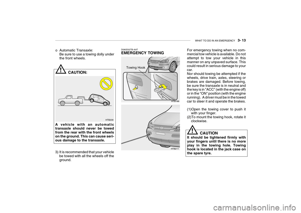
o Automatic Transaxle:
Be sure to use a towing dolly under the front wheels.
CAUTION:
A vehicle with an automatic transaxle should never be towed from the rear with the front wheelson the ground. This can cause seri- ous damage to the transaxle.
3) It is recommended that your vehicle be towed with all the wheels off the ground.
D080D02TB-AAT EMERGENCY TOWING For emergency towing when no com- mercial tow vehicle is available. Do not attempt to tow your vehicle in thismanner on any unpaved surface. This could result in serious damage to your car.Nor should towing be attempted if the wheels, drive train, axles, steering or brakes are damaged. Before towing,be sure the transaxle is in neutral and the key is in "ACC" (with the engine off) or in the "ON" position (with the enginerunning). A driver must be in the towed car to steer it and operate the brakes. (1)Open the towing cover to push it
with your finger.
(2)To mount the towing hook, rotate it clockwise.
HTB196
HTB211 CAUTION
It should be tightened firmly with your fingers until there is no moreplay in the towing hole. Towing hook is located in the jack case on the spare tyre.
!
Towing Hook
Page 153 of 437

6- 8 DO-IT-YOURSELF MAINTENANCE
Petrol engine
HTB169
HTB169A
Diesel engine
G030D01TB-EAT ENGINE OIL REPLENISHMENT
If the indicated oil level is at or below the lower mark of the dipstick, oil should be added until the level is at or below the upper mark.To add oil to the engine, remove the filler cap by rotating in an counterclock- wise direction and pour engine oil intothe engine. Before checking the level again, allow several minutes for the oil to drain into the sump. Replace the oilfiller cap rotating it in a clockwise direc- tion until tight. The quantity of oil required to raise thelevel from the minimum to maximum level is approximately 1.2 litre.ZG030E1-E ENGINE OIL CONSUMPTION Function of engine oil Engine oil has the primary function of lubricating and cooling the inside of the engine. Engine oil consumption It is normal that an engine should con- sume some engine oil while normal driving. The cause of oil consumption in a normal engine are as follows;
o Engine oil is used to lubricate pis-
tons, piston rings and cylinders. A thin film of oil is left on the cylinder wall when a piston moves down- wards in the cylinder. High negativepressure generated during engine operation sucks some of the oil into the combustion chamber.This oil with some oil of the cylinder wall is burned by the high tempera- ture combustion gases during thecombustion process.
o The engine oil consumption is strongly
effected by the viscosity and qualityof oil, engine rpm and driving condi- tion etc.
Page 155 of 437

6- 10 DO-IT-YOURSELF MAINTENANCE
!
!
HTB170
Petrol engine SG050A1-E ENGINE COOLANT CHECKING AND REPLACING
SG050B1-E Coolant recommendations WARNING:
Do not remove the radiator cap when the engine is hot, since the system is pressurized and coolant may be ejected from the radiator resulting inscalding.
3. Prepare a suitable receptacle to col-
lect the displaced oil and remove thedrain plug from the sump.
4. When the oil has drained from the sump, replace the drain plug using anew washer ensuring that the plug is not over tightened. Tightening torque is: 3.5 ~ 4.5 kgf.m
5. Remove the oil filter by rotating coun- terclockwise, using a proprietary oil filter removal tool if necessary. Notethat the oil filter will contain approxi- mately 0.5 litres of oil and this should be collected in a suitable receptacle.
6. Install a new oil filter having smeared the sealing ring with clean oil androtating clockwise until the filter con-tacts the mounting and then a further one half turn. Do not over-tighten CAUTION:
The oil being drained from the en- gine will be hot. Care should beexercised to prevent scalding.
! Tightening torque: Petrol -
1.2 ~ 1.6 kgf.m
Diesel(RHD) - 2.3 ~ 2.5 kgf.m
7. Pour the specified quantity of the recommended oil into the engine and replace the filler cap. Start the en- gine and ensure that no oil leaks exist. Turn off the engine and after acouple minutes, recheck the oil level.
WARNING:
Prolonged and repeated contact with used engine oils may result in seri- ous skin disorders including derma- titis and cancer. Avoid contact with skin as far as possible and alwayswash thoroughly after any contact. Keep used oils out of reach of chil- dren. It is illegal to pollute drains,water courses and soil. Use only authorized waste collection facili- ties including civic amenity sitesand garages for the disposal of used oil and oil filters. If in doubt, contact the local authority for disposal in-structions.
Page 158 of 437

DO-IT-YOURSELF MAINTENANCE 6- 13
SG060A1-E SPARKING PLUG REPLACE- MENT
G060A01L
0.039 ~ 0.043 in. (1.0 ~ 1.1 mm )
This operation should only be performed when the engine is cold.
1. Remove the centre cover from the engine rocker cover.
2. Remove plug lead from the sparking plug to be replaced, pulling the lead by the rubber cap. (Pulling the lead may damage the carbon conductor).
3. Clean around the base of the plug to be removed, and install the plugsocket ensuring that the ceramicinsulator does not become damaged. Turn the socket counterclockwise to remove the plug. CAUTION:
Sparking plugs must only be cleaned using purpose designed equipment. Wire brushing may damage the cen-tre electrode-insulator causing mis- firing to occur. Only the correct grade of sparking plug should be used.Use of an incorrect grade may result in serious engine damage. Prior to installing a sparking plug, the gap between the centre and outer elec- trodes must be checked and adjusted as necessary. Adjustment is facilitated by bending the outer electrode towards or away fromthe centre electrode. Under no circum- stances should attempts be made to adjust the position of the centre elec-trode.
4. Insert the sparking plug into the cyl- inder head and screw by the wrench and until the plug contacts the seat- ing area. Tighten the plug with the socket by a further 1/2 to 3/4 of a turnonly. 5. Replace the plug lead ensuring that
the cap is pushed firmly into place.Confirm that the cap is correctlyseated by lightly pulling upon it.
NOTE: When replacing the spark plug, al- ways use the genuine parts recom- mended. Recommended Spark Plugs
CHAMPION NGKRC10YC4 BKR5ES-11
!
Page 196 of 437

10- 2 INDEX
A AIR BAG ................................................................... 1-30
AIR CONDITIONING SWITCH .................................1-74
AIR CONDITIONING SYSTEM MAINTENANCE ..... 6-19
AIR CLEANER FILTER ............................................. 6-14
ANTENNA ................................................................. 1-84
ANTI-LOCK BRAKE SYSTEM .................................. 2-13
ANTI-THEFT ALARM SYSTEM .................................. 1-7
ASHTRAY ................................................................. 1-54
AUTO FUEL CUT SW ITCH...................................... 1-68
AUTOMATIC TRANSAXLE ......................................... 2-9AUTOMATIC TRANSAXLE FLUID ...........................6-16
BBATTERY MAINTENANCE ......................................6-25
BEFORE STARTING THE ENGINE ...........................2-3
BONNET RE LEASE.................................................. 1-62
BRAKE PEDAL FREEPLAY .....................................6-22
BRAKE SYSTEM CHECKING ..................................6-18
CCARE OF DISC ......................................................... 1-82
CARE OF SEAT BELTS .... .......................................1-19
CARGO AREA COVER ............................................ 1-66
CATALYTIC CONVERTOR OPERATING PRECAUTIONS ...................................................... 7-3
CENTRAL DOOR LOCKS .......................................... 1-5
CHANGING A FLAT TYRE ......................................... 3-6 CHILD-PROOF REAR DOOR
LOCK .......................... 1-5
CHILD RESTRAINT SYSTEM ..................................1-22
CIGAR LIGHTER ...................................................... 1-53
CLUTCH PEDAL FR EEPLAY................................... 6-22
COMBINATION IGNITION SWITCH AND STEERING LOCK ................................................... 2-3
CONSOLE TRAY ...................................................... 1-54
COOLANT TEMPERATURE GAUGE .......................1-44
DDAILY OPERATING CHECKS .................................... 6-6
DIGITAL CLOCK ....................................................... 1-53
DOOR LOCK S ............................................................ 1-5
DOOR WINDOWS .................................................... 1-10
DRINK HOLDER ....................................................... 1-54
DRIVE BELTS ........................................................... 6-23
DRIVING FOR ECONOMY .......................................2-14
EEFFECTIVE BRA KING............................................. 2-13
ELECTRIC COOLING FANS ....................................6-25
EMERGENCY TOWING .... .......................................3-12
EMISSION CONTROL SYSTEM ................................ 7-2
ENGINE COMPARTMENT .................... ..................... 6-2
ENGINE COOLANT CHECKING AND REPLACING ......................................................... 6-10
ENGINE OIL AND FILTER REPLACEMENT .............. 6-9
ENGINE OIL CONSUMPTION ................................... 6-8
Page 224 of 437

1- 12 FEATURES OF YOUR HYUNDAI
HTB257
B050A01A-AAT WINDOW GLASS
To raise or lower the window, turn the window regulator handle clockwise or counterclockwise.HTB064
(1) HTB066
In order to prevent operation of the passenger front and rear windows, a window lock switch is provided on thearmrest of the driver's door. To disable the power windows, press the window lock switch.To revert to normal operation, press the window lock switch a second time. Auto-Down Window (Driver's Side) The Auto-Down window is moved to its fully open position by pushing the switch. To stop at the desired positionpush the switch again.
B060A01E-AAT POWER WINDOWS (If Installed)
The power windows operate when the ignition key is in the "ON" position. The main switches are located on thedriver's armrest and control the front and rear windows on both sides of the vehicle. The windows may be openedby depressing the appropriate window switch and closed by pulling up the switch. To open the window on thedriver's side, press the switch(1) down. The window moves as long as the switch is operated.
WARNING:
When opening or closing the win-dows, make sure your passenger's arms, hands and body are safely out of the way.
!
TBENG_1A.P65 3/9/2005, 4:57 PM
12
Page 250 of 437

1- 38 FEATURES OF YOUR HYUNDAI
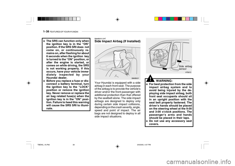
B990B03Y-GAT Side Impact Airbag (If Installed) Your Hyundai is equipped with a side airbag in each front seat. The purpose of the airbag is to provide the vehicle's driver and/or the front passenger withadditional protection than that offered by the seatbelt alone. The side impact airbags are designed to deploy onlyduring certain side impact collisions, depending on the crash severity, angle, speed and point of impact. The airbags are not designed to deploy in all side impact situations.o The SRS can function only when
the ignition key is in the "ON" position. If the SRS SRI does not come on, or continuously re-mains on, after flashing for about 6 seconds when the ignition key is turned to the "ON" position, orafter the engine is started, or comes on while driving, the SRS is not working properly. If thisoccurs, have your vehicle imme- diately inspected by your Hyundai dealer.
o Before you replace a fuse or dis- connect a battery terminal, turnthe ignition key to the "LOCK"position or remove the ignition key. Never remove or replace the air bag related fuse(s) when theignition key is in the "ON" posi- tion. Failure to heed this warning will cause the SRS SRI to illumi-nate.
B990B02Y
HTB072
Side airbag sensor
!WARNING:
o For best protection from the side impact airbag system and to avoid being injured by the de- ploying side impact airbag, bothfront seat occupants should sit in an upright position with the seat belt properly fastened. Thedriver's hands should be placed on the steering wheel at the 9:00 and 3:00 o'clock positions. Thepassenger's arms and hands should be placed in their laps.
o Do not use any accessory seat covers.
TBENG_1A.P65 3/9/2005, 4:57 PM
38
Page 253 of 437

FEATURES OF YOUR HYUNDAI 1- 41
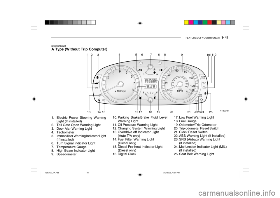
B260B02TB-GAT A Type (Without Trip Computer)
1. Electric Power Steering Warning Light (If installed)
2. Tail Gate Open Warning Light
3. Door Ajar Warning Light
4. Tachometer
5. Immobilizer Warning Indicator Light (If installed)
6. Turn Signal Indicator Light
7. Temperature Gauge
8. High Beam Indicator Light
9. Speedometer HTB001B
10. Parking Brake/Brake Fluid Level Warning Light
11. Oil Pressure Warning Light
12. Charging System Warning Light
13. Overdrive off Indicator Light (Auto T/A only)
14. Fuel Filter Warning Light
(Diesel only)
15. Diesel Pre-heat Indicator Light (Diesel only)
16. Digital Clock 17. Low Fuel Warning Light
18. Fuel Gauge
19. Odometer/Trip Odometer
20. Trip odometer Reset Switch
21. Clock Reset Switch
22. ABS Warning Light (If installed)
23. SRS (Airbag) Warning Light
(If installed)
24. Malfunction Indicator Light (MIL) (If installed)
25. Seat Belt Warning Light
1
2
453 6
7 8
9 1011
12
13 14
15 16
17 18
19 20 2122
23 24
6
25
TBENG_1A.P65 3/9/2005, 4:57 PM
41
Page 254 of 437

1- 42 FEATURES OF YOUR HYUNDAI
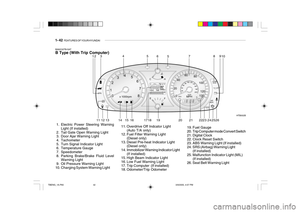
B260C02TB-GAT B Type (With Trip Computer)
1. Electric Power Steering Warning Light (If installed)
2. Tail Gate Open Warning Light
3. Door Ajar Warning Light
4. Tachometer
5. Turn Signal Indicator Light
6. Temperature Gauge
7. Speedometer
8. Parking Brake/Brake Fluid Level Warning Light
9. Oil Pressure Warning Light
10. Charging System Warning Light HTB002B
11. Overdrive Off Indcator Light (Auto T/A only)
12. Fuel Filter Warning Light
(Diesel only)
13. Diesel Pre-heat Indicator Light (Diesel only)
14. Immobilizer Warning Indicator Light (If installed)
15. High Beam Indicator Light
16. Low Fuel Warning Light
17. Trip Computer (If installed)
18. Odometer/Trip Odometer 19. Fuel Gauge
20. Trip Computer mode Convert Switch
21. Digital Clock
22. Clock Reset Switch
23. ABS Warning Light (If installed)
24. SRS (Airbag) Warning Light
(If installed)
25. Malfunction Indicator Light (MIL)
(If installed)
26. Seat Belt Warning Light
12 3 4
5
5
67 8
910
11 12 13 14 15 16 17 18 19 20 23 24
252221 26
TBENG_1A.P65 3/9/2005, 4:57 PM
42