Hyundai Getz 2008 Owner's Manual
Manufacturer: HYUNDAI, Model Year: 2008, Model line: Getz, Model: Hyundai Getz 2008Pages: 383, PDF Size: 9.23 MB
Page 341 of 383
6- 12 DO-IT-YOURSELF MAINTENANCE
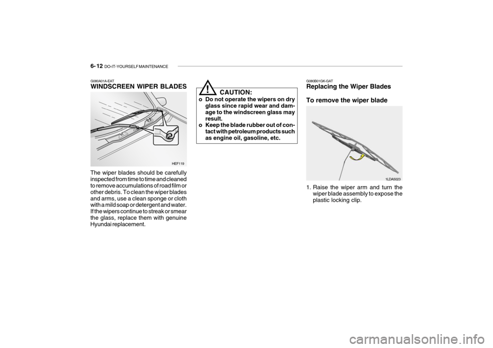
G080A01A-EAT WINDSCREEN WIPER BLADES
The wiper blades should be carefully inspected from time to time and cleaned to remove accumulations of road film or other debris. To clean the wiper bladesand arms, use a clean sponge or cloth with a mild soap or detergent and water. If the wipers continue to streak or smearthe glass, replace them with genuine Hyundai replacement. HEF119CAUTION:
o Do not operate the wipers on dry glass since rapid wear and dam- age to the windscreen glass mayresult.
o Keep the blade rubber out of con-
tact with petroleum products suchas engine oil, gasoline, etc.
!
G080B01GK-GAT Replacing the Wiper Blades To remove the wiper blade
1. Raise the wiper arm and turn thewiper blade assembly to expose the plastic locking clip. 1LDA5023
Page 342 of 383
DO-IT-YOURSELF MAINTENANCE 6- 13
SG090A2-E WINDSCREEN WASHER RES- ERVOIR REPLENISHMENT
HTB173
HTB173A
Gasoline Engine
Diesel Engine
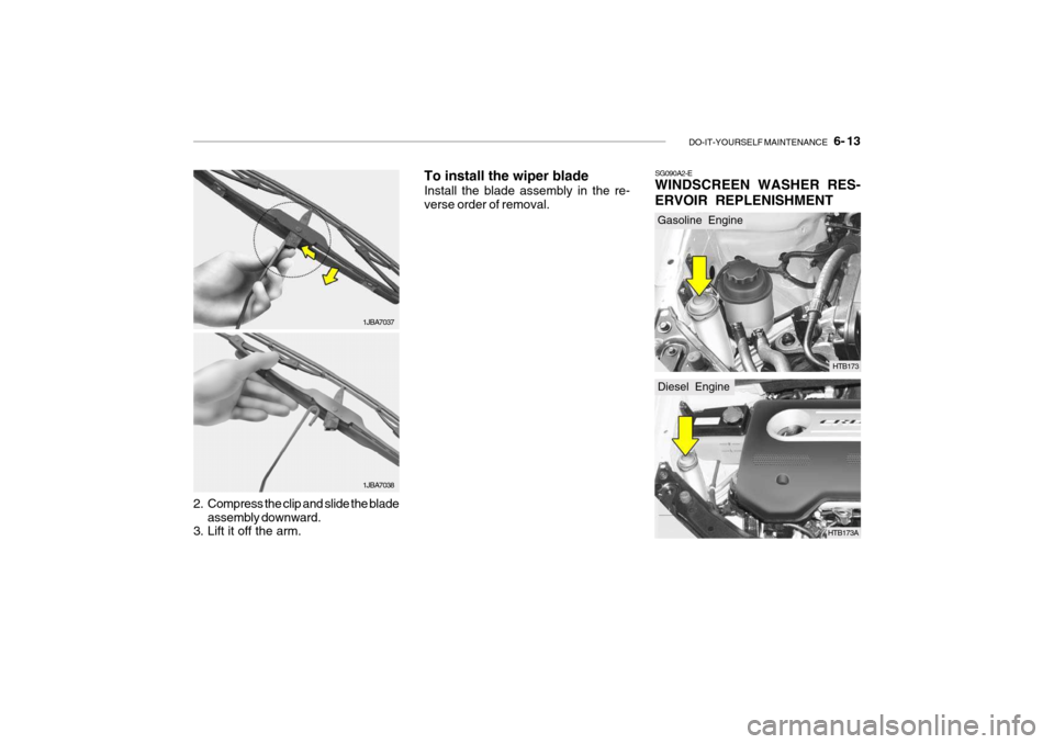
2. Compress the clip and slide the bladeassembly downward.
3. Lift it off the arm. 1JBA7037
1JBA7038To install the wiper blade Install the blade assembly in the re- verse order of removal.
Page 343 of 383
6- 14 DO-IT-YOURSELF MAINTENANCE
!
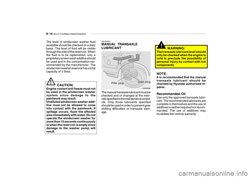
SG100A3-E MANUAL TRANSAXLE LUBRICANT
CAUTION:
Engine coolant anti freeze must not be used in the windscreen washersystem since damage to the paintwork may result. Undiluted windscreen washer addi-tive must not be allowed to come into contact with the paintwork. If spillage occurs, flush the affectedarea immediately with water. Do not operate the windscreen washer for more than 15 seconds continuouslyor when the reservoir is empty since damage to the washer pump will result.
!
HXGS506
Drain plug
Filler plug
The manual transaxle lubricant must be checked and or changed at the inter- vals specified in the maintenance sched- ule. Only those lubricants specifiedshould be used in order to prevent gear shifting difficulties or transaxle dam- age. WARNING:
The transaxle lubricant level should only be checked when the engine is cold to preclude the possibility ofpersonal injury by contact with hot components. NOTE: It is recommended that the manual transaxle lubricant should be checked by Hyundai authorised re- pairer. Recommended Oil Use only the approved transaxle lubri- cant. The recommended lubricants arecomplete in themselves and the use of additives is neither required nor recom- mended. The use of additives mayinvalidate the vehicle warranty.
The level of windscreen washer fluid available should be checked on a daily basis. The level of fluid will be visiblethrough the side of the reservoir. When the fluid is to be replenished, only a proprietary screen wash additive shouldbe used and in the concentration rec- ommended by the manufacturer. The windscreen washer reservoir has a totalcapacity of 3 litres.
Page 344 of 383
DO-IT-YOURSELF MAINTENANCE 6- 15
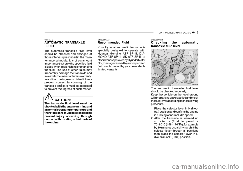
G100B03A-GAT Checking the automatic transaxle fluid level
SG110A1-E AUTOMATIC TRANSAXLE FLUID The automatic transaxle fluid level should be checked and changed at those intervals prescribed in the main-tenance schedule. It is of paramount importance that only the specified fluid is used when replenishing or changingthe fluid. The use of other fluids may irreparably damage the transaxle and invalidate the manufacturers warranty.In addition the ingress of dirt or lint may prevent correct functioning of the transaxle and care must be exercisedto prevent the ingress of such matter.
CAUTION:
The transaxle fluid level must bechecked with the engine running and at normal operating temperature and therefore care must be exercised toprevent injury occurring through contact with rotating or hot parts of the engine.
! G110B04A-AAT Recommended Fluid Your Hyundai automatic transaxle is specially designed to operate withHyundai Genuine ATF SP-III, DIA- MOND ATF SP-III, SK ATF SP-III or other brands approved by Hyundai MotorCo., Damage caused by a nonspecified fluid is not covered by your new vehicle limited warranty.
The automatic transaxle fluid level should be checked regularly. Keep the vehicle on the level groundwith the parking brake applied and check the fluid level according to the following procedure.
1. Place the selector lever in N (Neu-tral) position and confirm the engine is running at normal idle speed.
2. After the transaxle is warmed up
sufficiently (fluid temperature70~80°C (158~176°F)), for example by 10 minutes usual driving, shift the selector lever through all positionsthen place the selector lever in N (Neutral) or P (Park) position.
HTB164
Page 345 of 383
6- 16 DO-IT-YOURSELF MAINTENANCE
fuel leaks may cause serious injury, if it touch the body. People using pacemakers should not move than30cm closer to the ECU or wiring harness within the engine room while engine is running, since the highcurrents in the Common Rail system produce considerable magnetic fields.
!
CAUTION:
The automatic transaxle unit is a precision engineered assembly andcorrect operation is dependant upon the exclusion of dirt and lint from the unit. Therefore, it is imperative thatonly lint free cloth (eg nylon) is used for wiping the dipstick and that the area around the dipstick is thor-oughly clean prior to level checking or adding fluid. Fluid Capacity The total fluid capacity of the transaxle unit is 6.1 litres.
!
!
C090A03FC
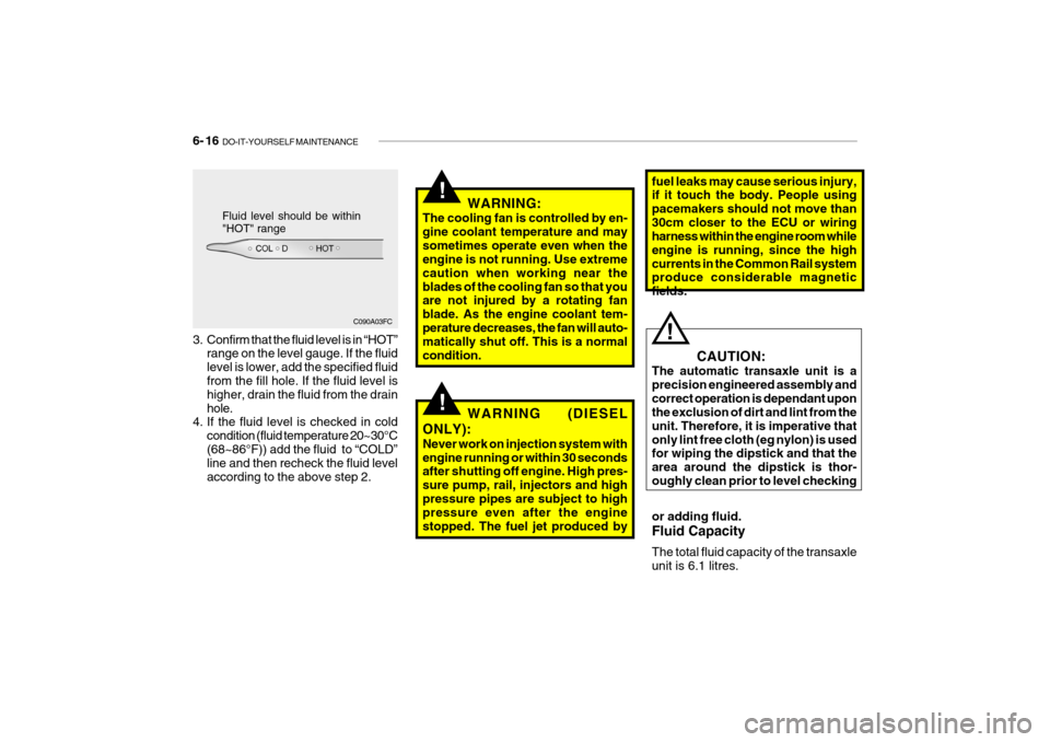
Fluid level should be within "HOT" range
3. Confirm that the fluid level is in “HOT” range on the level gauge. If the fluid level is lower, add the specified fluid from the fill hole. If the fluid level is higher, drain the fluid from the drainhole.
4. If the fluid level is checked in cold
condition (fluid temperature 20~30°C(68~86°F)) add the fluid to “COLD” line and then recheck the fluid level according to the above step 2. WARNING:
The cooling fan is controlled by en-gine coolant temperature and maysometimes operate even when the engine is not running. Use extreme caution when working near theblades of the cooling fan so that you are not injured by a rotating fan blade. As the engine coolant tem-perature decreases, the fan will auto- matically shut off. This is a normal condition.
WARNING (DIESEL
ONLY): Never work on injection system with engine running or within 30 seconds after shutting off engine. High pres- sure pump, rail, injectors and highpressure pipes are subject to high pressure even after the engine stopped. The fuel jet produced by
Page 346 of 383
DO-IT-YOURSELF MAINTENANCE 6- 17
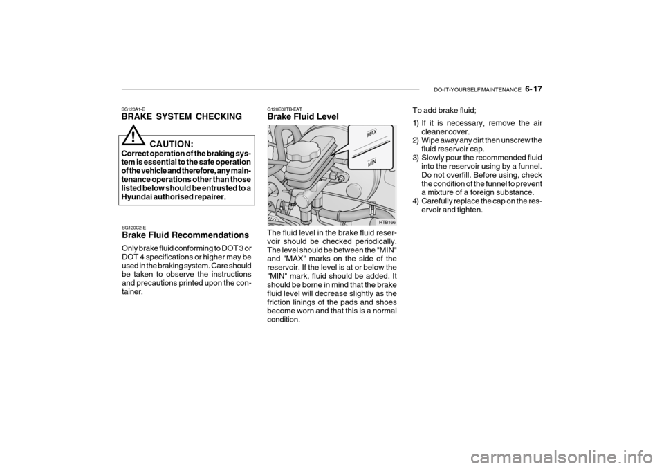
G120E02TB-EAT Brake Fluid Level
SG120A1-EBRAKE SYSTEM CHECKING
SG120C2-E Brake Fluid Recommendations Only brake fluid conforming to DOT 3 or DOT 4 specifications or higher may beused in the braking system. Care should be taken to observe the instructions and precautions printed upon the con-tainer.
!
CAUTION:
Correct operation of the braking sys- tem is essential to the safe operation of the vehicle and therefore, any main-tenance operations other than those listed below should be entrusted to a Hyundai authorised repairer.
The fluid level in the brake fluid reser-voir should be checked periodically.The level should be between the "MIN" and "MAX" marks on the side of the reservoir. If the level is at or below the"MIN" mark, fluid should be added. It should be borne in mind that the brake fluid level will decrease slightly as thefriction linings of the pads and shoes become worn and that this is a normal condition.
HTB166To add brake fluid;
1) If it is necessary, remove the air
cleaner cover.
2) Wipe away any dirt then unscrew the
fluid reservoir cap.
3) Slowly pour the recommended fluid into the reservoir using by a funnel. Do not overfill. Before using, checkthe condition of the funnel to prevent a mixture of a foreign substance.
4) Carefully replace the cap on the res- ervoir and tighten.
Page 347 of 383
6- 18 DO-IT-YOURSELF MAINTENANCE
SG140C1-E Checking the Refrigerant
1. Start the engine and run at idle for
several minutes with the refrigera- tion system running at the coldest setting.
2. Open the bonnet and inspect the
sight glass on the top of the receiverdryer.
3. If the refrigerant charge is insuffi- cient, a flow of bubbles will be ob-served through the sight glass.
4. If the refrigerant charge is satisfac- tory, no bubbles will be observedthrough the sight glass.
CAUTION:
Running the air conditioning systemwith a low refrigerant level may dam- age the compressor.
!
!WARNING:
Brake fluid is hygroscopic and should never be stored in an un-sealed container. The presence of water in the braking system will cause vapour locks and increase the possi-bility of brake fade along with pro- moting corrosion within the braking system. The brake fluid must bechanged at the specified time or mile- age interval to ensure continued safe operation of the system. Brake fluid will cause rapid and serious damage to paintwork. If accidental spillageoccurs, the affected area must be rinsed with water immediately. Do not allow brake fluid to come intocontact with the eyes or to be in- gested and ensure that fluid is safely stored away form the reach of chil-dren. SG140A1-E AIR CONDITIONING SYSTEM MAINTENANCECondenser Ensure that the condenser is periodi- cally inspected and that accumulations of dirt, dead insects and leaves etc, areremoved to ensure that the efficiency of the system is not impaired. Care must be exercised to ensure that the con-denser fins are not damaged during cleaning.
Page 348 of 383
DO-IT-YOURSELF MAINTENANCE 6- 19
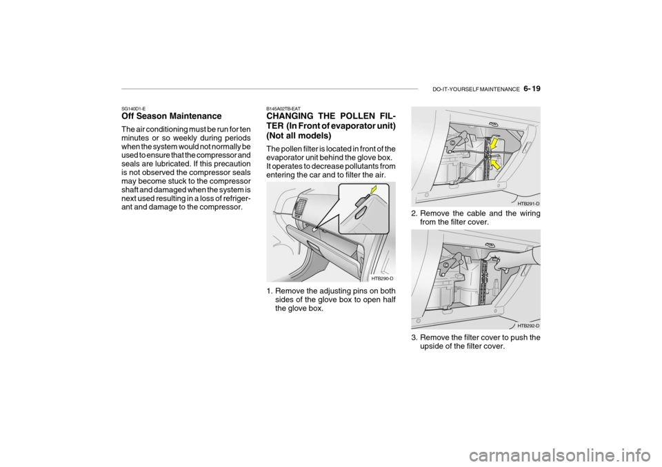
B145A02TB-EAT CHANGING THE POLLEN FIL-
TER (In Front of evaporator unit)(Not all models) The pollen filter is located in front of the evaporator unit behind the glove box. It operates to decrease pollutants fromentering the car and to filter the air.
1. Remove the adjusting pins on both
sides of the glove box to open half the glove box.
HTB290-D
SG140D1-E Off Season Maintenance The air conditioning must be run for ten minutes or so weekly during periodswhen the system would not normally be used to ensure that the compressor and seals are lubricated. If this precautionis not observed the compressor seals may become stuck to the compressor shaft and damaged when the system isnext used resulting in a loss of refriger- ant and damage to the compressor.
3. Remove the filter cover to push theupside of the filter cover.
HTB291-D
2. Remove the cable and the wiring from the filter cover.
HTB292-D
Page 349 of 383
6- 20 DO-IT-YOURSELF MAINTENANCE
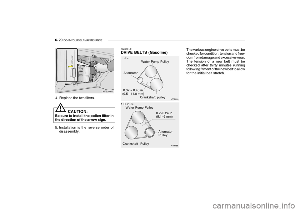
The various engine drive belts must be checked for condition, tension and free- dom from damage and excessive wear.The tension of a new belt must be checked after thirty minutes running following fitment of the new belt to allowfor the initial belt stretch.
Crankshaft Pulley
SG190A1-E DRIVE BELTS (Gasoline)
1.1L
1.3L/1.6L Alternator
0.37 ~ 0.43 in. (9.5 ~11.0 mm)
Water Pump Pulley
Alternator Pulley
0.2~0.24 in.(5.1~6 mm)
HTB186
Crankshaft pulley
HTB220
Water Pump Pulley
HTB293-D
4. Replace the two filters.
CAUTION:
Be sure to install the pollen filter in the direction of the arrow sign.
5. Installation is the reverse order of disassembly.
!
Page 350 of 383
DO-IT-YOURSELF MAINTENANCE 6- 21
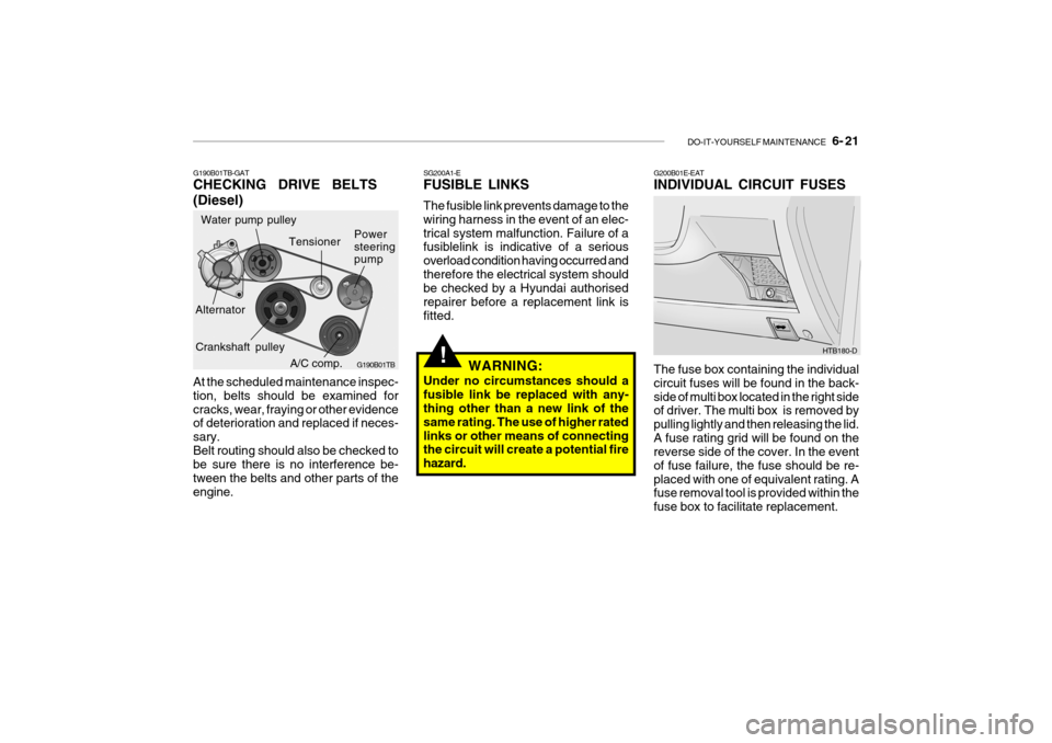
G190B01TB-GAT CHECKING DRIVE BELTS (Diesel) At the scheduled maintenance inspec- tion, belts should be examined forcracks, wear, fraying or other evidence of deterioration and replaced if neces- sary.Belt routing should also be checked to be sure there is no interference be- tween the belts and other parts of theengine.
!
SG200A1-E FUSIBLE LINKS The fusible link prevents damage to the wiring harness in the event of an elec-trical system malfunction. Failure of a fusiblelink is indicative of a serious overload condition having occurred andtherefore the electrical system should be checked by a Hyundai authorised repairer before a replacement link isfitted.
WARNING:
Under no circumstances should afusible link be replaced with any- thing other than a new link of the same rating. The use of higher ratedlinks or other means of connecting the circuit will create a potential fire hazard.G200B01E-EAT INDIVIDUAL CIRCUIT FUSES The fuse box containing the individual circuit fuses will be found in the back-side of multi box located in the right side of driver. The multi box is removed by pulling lightly and then releasing the lid.A fuse rating grid will be found on the reverse side of the cover. In the event of fuse failure, the fuse should be re-placed with one of equivalent rating. A fuse removal tool is provided within the fuse box to facilitate replacement. HTB180-D
A/C comp.
Water pump pulley
G190B01TB
Alternator Power steering pump
Tensioner
Crankshaft pulley