turn signal Hyundai Grand Santa Fe 2016 Owner's Manual
[x] Cancel search | Manufacturer: HYUNDAI, Model Year: 2016, Model line: Grand Santa Fe, Model: Hyundai Grand Santa Fe 2016Pages: 717, PDF Size: 18.59 MB
Page 74 of 717
355
Safety features of your vehicle
How does the air bag system
operate
• Air bags are activated (able to
inflate if necessary) only when the
ignition switch is turned to the ON
or START position.
• Air bags inflate instantly in the
event of serious frontal or side col-
lision (if equipped with side impact
air bag or curtain air bag) in order
to help protect the occupants from
serious physical injury.
✽NOTICE - if equipped with
rollover sensor
Also, the air bags inflate instantly in
the event of a rollover (if equipped
with a side air bag or curtain air bag)
in order to help protect the occu-
pants from serious physical injury.
• There is no single speed at which
the air bags will inflate.
Generally, air bags are designed to
inflate based upon the severity of a
collision and its direction. These
two factors determine whether the
sensors produce an electronic
deployment/inflation signal.• Air bag deployment depends on a
number of factors including vehicle
speed, angles of impact and the
density and stiffness of the vehi-
cles or objects which your vehicle
hits in the collision. The determin-
ing, factors are not limited to those
mentioned above.
• The front air bags will completely
inflate and deflate in an instant.
It is virtually impossible for you to
see the air bags inflate during an
accident. It is much more likely that
you will simply see the deflated air
bags hanging out of their storage
compartments after the collision.
• In order to help provide protection
in a severe collision, the air bags
must inflate rapidly. The speed of
air bag inflation is a consequence
of extremely short time in which a
collision occurs and the need to
get the air bag between the occu-
pant and the vehicle structures
before the occupant impacts those
structures. This speed of inflation
reduces the risk of serious or life-
threatening injuries in a severe col-
lision and is thus a necessary part
of air bag design.However, air bag inflation can also
cause injuries which can include
facial abrasions, bruises and bro-
ken bones because the inflation
speed also causes the air bags to
expand with a great deal of force.
• There are even circumstances
under which contact with the
steering wheel air bag can cause
fatal injuries, especially if the
occupant is positioned exces-
sively close to the steering wheel.
WARNING
• To avoid severe personal
injury or death caused by
deploying air bags in a colli-
sion, the driver should sit as
far back from the steering
wheel air bag as possible (at
least 250 mm (10 inches)
away). The front passenger
should always move their seat
as far back as possible and sit
back in their seat.
(Continued)
Page 99 of 717
Instrument cluster . . . . . . . . . . . . . . . . . . . . . . . . . 4-63
• Instrument cluster control . . . . . . . . . . . . . . . . . . . . . 4-65
• LCD display control . . . . . . . . . . . . . . . . . . . . . . . . . . 4-65
• Gauges . . . . . . . . . . . . . . . . . . . . . . . . . . . . . . . . . . . . . 4-66
• Transaxle shift indicator . . . . . . . . . . . . . . . . . . . . . . . 4-71
LCD display . . . . . . . . . . . . . . . . . . . . . . . . . . . . . . 4-72
• LCD modes. . . . . . . . . . . . . . . . . . . . . . . . . . . . . . . . . . 4-72
• Service mode . . . . . . . . . . . . . . . . . . . . . . . . . . . . . . . . 4-73
• User settings mode. . . . . . . . . . . . . . . . . . . . . . . . . . . . 4-74
• A/V mode . . . . . . . . . . . . . . . . . . . . . . . . . . . . . . . . . . . 4-77
• Turn by turn mode . . . . . . . . . . . . . . . . . . . . . . . . . . . 4-77
• Warning messages . . . . . . . . . . . . . . . . . . . . . . . . . . . . 4-78
Trip computer . . . . . . . . . . . . . . . . . . . . . . . . . . . . . 4-84
• Overview. . . . . . . . . . . . . . . . . . . . . . . . . . . . . . . . . . . . 4-84
• Trip A/B . . . . . . . . . . . . . . . . . . . . . . . . . . . . . . . . . . . . 4-85
• Fuel economy . . . . . . . . . . . . . . . . . . . . . . . . . . . . . . . . 4-86
Warning and indicator lights . . . . . . . . . . . . . . . . 4-89
• Warning lights . . . . . . . . . . . . . . . . . . . . . . . . . . . . . . . 4-89
• Indicator lights. . . . . . . . . . . . . . . . . . . . . . . . . . . . . . . 4-99
Rear parking assist system . . . . . . . . . . . . . . . . . 4-104
• Operation . . . . . . . . . . . . . . . . . . . . . . . . . . . . . . . . . . 4-104
• Non-operational conditions . . . . . . . . . . . . . . . . . . . 4-105
• Rear parking assist system precautions . . . . . . . . . 4-106
• Self-diagnosis . . . . . . . . . . . . . . . . . . . . . . . . . . . . . . . 4-107
Parking assist system . . . . . . . . . . . . . . . . . . . . . . 4-108
• Operation . . . . . . . . . . . . . . . . . . . . . . . . . . . . . . . . . . 4-109
• Non-operational conditions . . . . . . . . . . . . . . . . . . . 4-111
• Self-diagnosis . . . . . . . . . . . . . . . . . . . . . . . . . . . . . . . 4-112
Smart parking assist system (SPAS) . . . . . . . . . 4-113
• Operating condition . . . . . . . . . . . . . . . . . . . . . . . . . 4-114
• Non-operating condition . . . . . . . . . . . . . . . . . . . . . . 4-114
• How the system works . . . . . . . . . . . . . . . . . . . . . . . 4-117
• Additional instructions (messages) . . . . . . . . . . . . . 4-123
• System malfunction . . . . . . . . . . . . . . . . . . . . . . . . . . 4-124
Rearview camera . . . . . . . . . . . . . . . . . . . . . . . . . 4-125
Hazard warning flasher . . . . . . . . . . . . . . . . . . . . 4-126
Lighting . . . . . . . . . . . . . . . . . . . . . . . . . . . . . . . . . 4-127
• Battery saver function. . . . . . . . . . . . . . . . . . . . . . . . 4-127
• Headlight (Headlamp) escort function . . . . . . . . . . 4-127
• Lighting control . . . . . . . . . . . . . . . . . . . . . . . . . . . . . 4-127
• Traffic change . . . . . . . . . . . . . . . . . . . . . . . . . . . . . . 4-129
• High - beam operation . . . . . . . . . . . . . . . . . . . . . . . 4-131
• Turn signals and lane change signals . . . . . . . . . . . 4-132
• Front fog light . . . . . . . . . . . . . . . . . . . . . . . . . . . . . . 4-132
• Rear fog light . . . . . . . . . . . . . . . . . . . . . . . . . . . . . . . 4-133
• Daytime running light . . . . . . . . . . . . . . . . . . . . . . . . 4-134
• Headlight leveling device . . . . . . . . . . . . . . . . . . . . . 4-134
• Adaptive front lighting system (AFLS) . . . . . . . . . . 4-135
4
Page 111 of 717
Features of your vehicle
14 4
(Continued)
- Another vehicle’s smart key is
being operated close to your
vehicle.
When the smart key does not
work properly, open and close the
door with the mechanical key. If
you have a problem with the
smart key, we recommend that
you contact an authorized
HYUNDAI dealer.
• If the smart key is in close proxim-
ity to your cell phone or smart
phone, the signal from the smart
key could be blocked by normal
operation of your cell phone or
smart phone. This is especially
important when the phone is
active such as making call, receiv-
ing calls, text messaging, and/or
sending/ receiving emails. Avoid
placing the smart key and your
cell phone or smart phone in the
same pants or jacket pocket and
maintain adequate distance
between the two devices.Door lock/unlock in an emer-
gency situation
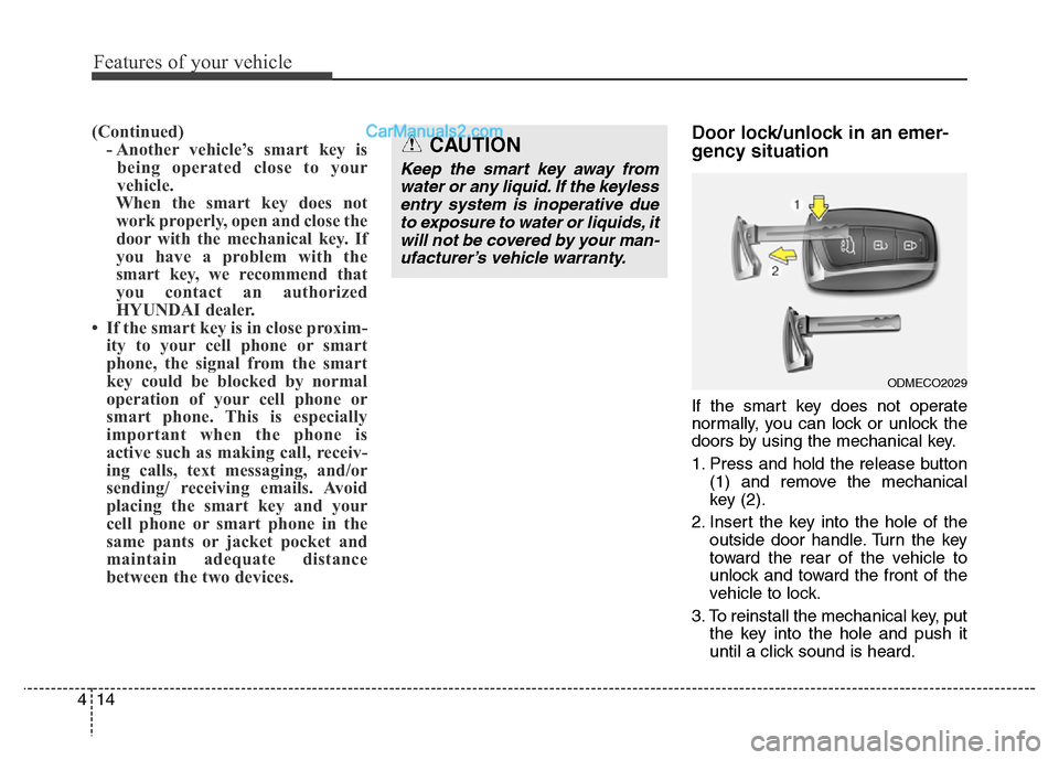
If the smart key does not operate
normally, you can lock or unlock the
doors by using the mechanical key.
1. Press and hold the release button
(1) and remove the mechanical
key (2).
2. Insert the key into the hole of the
outside door handle. Turn the key
toward the rear of the vehicle to
unlock and toward the front of the
vehicle to lock.
3. To reinstall the mechanical key, put
the key into the hole and push it
until a click sound is heard.
CAUTION
Keep the smart key away from
water or any liquid. If the keyless
entry system is inoperative due
to exposure to water or liquids, it
will not be covered by your man-
ufacturer’s vehicle warranty.
ODMECO2029
Page 160 of 717
463
Features of your vehicle
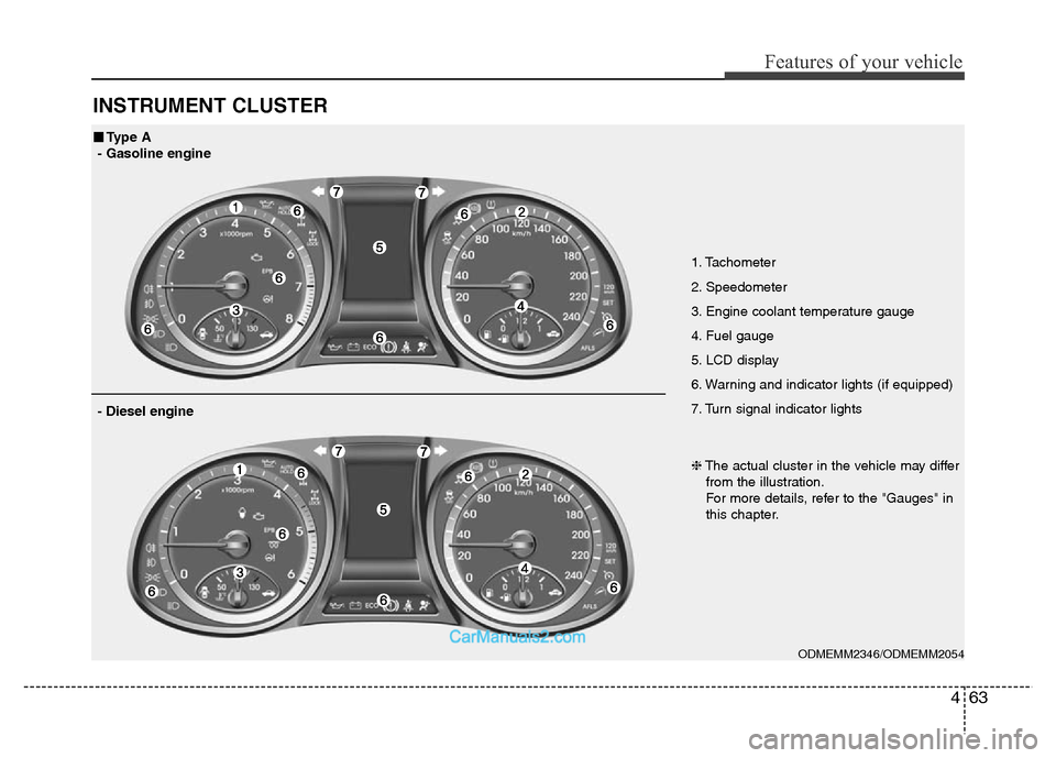
INSTRUMENT CLUSTER
1. Tachometer
2. Speedometer
3. Engine coolant temperature gauge
4. Fuel gauge
5. LCD display
6. Warning and indicator lights (if equipped)
7. Turn signal indicator lights
ODMEMM2346/ODMEMM2054
■Type A
- Gasoline engine
❈The actual cluster in the vehicle may differ
from the illustration.
For more details, refer to the "Gauges" in
this chapter.
- Diesel engine
Page 161 of 717
Features of your vehicle
64 4
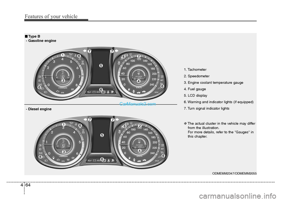
1. Tachometer
2. Speedometer
3. Engine coolant temperature gauge
4. Fuel gauge
5. LCD display
6. Warning and indicator lights (if equipped)
7. Turn signal indicator lights
ODMEMM2347/ODMEMM2055
■Type B
- Gasoline engine
❈The actual cluster in the vehicle may differ
from the illustration.
For more details, refer to the "Gauges" in
this chapter.
- Diesel engine
Page 172 of 717
475
Features of your vehicle
Auto Door Unlock (if equipped)
• Off:
The auto door unlock operation will
be canceled.
• Key Out or Power Off:
All doors will be automatically
unlocked when the ignition key is
removed from ignition switch or
Engine Star/Stop Button is set to
the OFF position.
• Driver Door Unlock:
All doors will be automatically
unlocked if the driver's door is
unlocked.
• Shift Lever:
All doors will be automatically
unlocked if the automatic transaxle
shift lever is shifted to the P (Park)
position.Horn Feedback (if equipped)
• Off:
The Horn feedback operation will
be deactivated.
• On:
After locking the door by pressing
the lock button on the transmitter, if
you press the lock button again
within 4 seconds, the warning
sound will operate once to indicate
that all doors are locked.
Power Tailgate (if equipped)
If this item is checked, the power tail-
gate function will be activated.
Smart Tailgate (if equipped)
If this item is checked, the smart tail-
gate function will be activated.Lamp
Head Lamp Delay (if equipped)
If this item is checked, the headlamp
delay and headlamp welcome func-
tion will be activated.
Welcome Light (if equipped)
If this item is checked, the welcome
light function of the puddle lamp will
be activated.
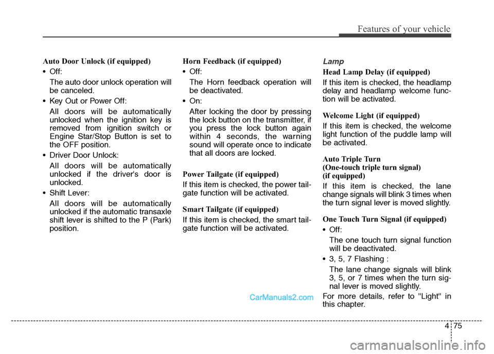
Auto Triple Turn
(One-touch triple turn signal)
(if equipped)
If this item is checked, the lane
change signals will blink 3 times when
the turn signal lever is moved slightly.
One Touch Turn Signal (if equipped)
• Off:
The one touch turn signal function
will be deactivated.
• 3, 5, 7 Flashing :
The lane change signals will blink
3, 5, or 7 times when the turn sig-
nal lever is moved slightly.
For more details, refer to ''Light'' in
this chapter.
Page 198 of 717
4101
Features of your vehicle
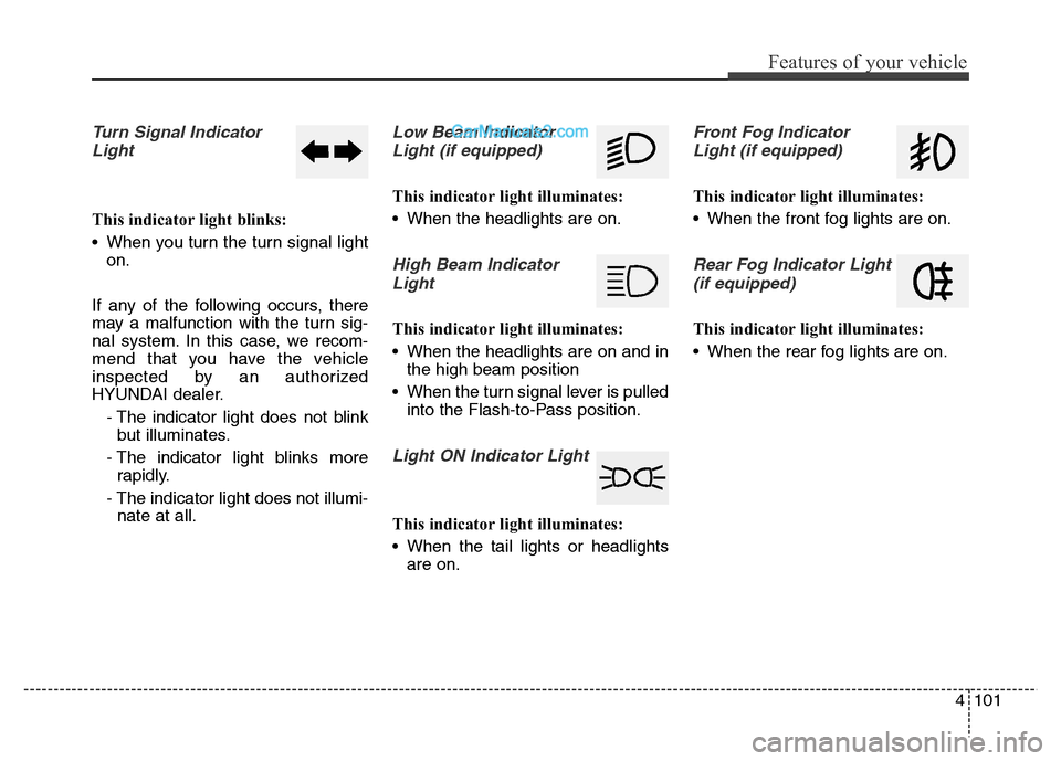
Turn Signal Indicator
Light
This indicator light blinks:
• When you turn the turn signal light
on.
If any of the following occurs, there
may a malfunction with the turn sig-
nal system. In this case, we recom-
mend that you have the vehicle
inspected by an authorized
HYUNDAI dealer.
- The indicator light does not blink
but illuminates.
- The indicator light blinks more
rapidly.
- The indicator light does not illumi-
nate at all.
Low Beam Indicator
Light (if equipped)
This indicator light illuminates:
• When the headlights are on.
High Beam Indicator
Light
This indicator light illuminates:
• When the headlights are on and in
the high beam position
• When the turn signal lever is pulled
into the Flash-to-Pass position.
Light ON Indicator Light
This indicator light illuminates:
• When the tail lights or headlights
are on.
Front Fog Indicator
Light (if equipped)
This indicator light illuminates:
• When the front fog lights are on.
Rear Fog Indicator Light
(if equipped)
This indicator light illuminates:
• When the rear fog lights are on.
Page 223 of 717
Features of your vehicle
126 4
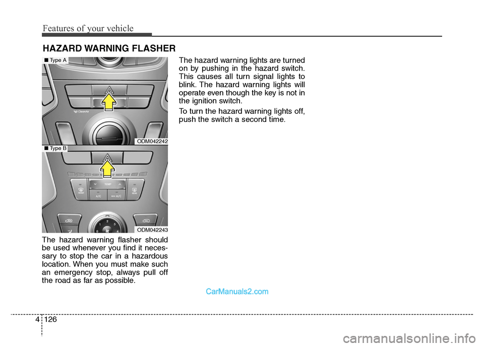
The hazard warning flasher should
be used whenever you find it neces-
sary to stop the car in a hazardous
location. When you must make such
an emergency stop, always pull off
the road as far as possible.The hazard warning lights are turned
on by pushing in the hazard switch.
This causes all turn signal lights to
blink. The hazard warning lights will
operate even though the key is not in
the ignition switch.
To turn the hazard warning lights off,
push the switch a second time.
HAZARD WARNING FLASHER
ODM042242
ODM042243
■Type A
■Type B
Page 229 of 717
Features of your vehicle
132 4
Turn signals and lane change
signals
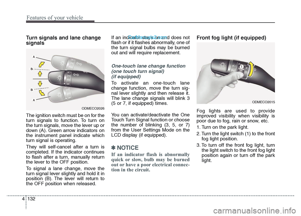
The ignition switch must be on for the
turn signals to function. To turn on
the turn signals, move the lever up or
down (A). Green arrow indicators on
the instrument panel indicate which
turn signal is operating.
They will self-cancel after a turn is
completed. If the indicator continues
to flash after a turn, manually return
the lever to the OFF position.
To signal a lane change, move the
turn signal lever slightly and hold it in
position (B). The lever will return to
the OFF position when released.If an indicator stays on and does not
flash or if it flashes abnormally, one of
the turn signal bulbs may be burned
out and will require replacement.
One-touch lane change function
(one touch turn signal)
(if equipped)
To activate an one-touch lane
change function, move the turn sig-
nal lever slightly and then release it.
The lane change signals will blink 3
(5 or 7, if equipped) times.
You can activate/deactivate the One
Touch Turn Signal function or choose
the number of blinking (3, 5, or 7)
from the User Settings Mode on the
LCD display (if equipped).
✽NOTICE
If an indicator flash is abnormally
quick or slow, bulb may be burned
out or have a poor electrical connec-
tion in the circuit.
Front fog light (if equipped)
Fog lights are used to provide
improved visibility when visibility is
poor due to fog, rain or snow, etc.
1. Turn on the park light.
2. Turn the light switch (1) to the front
fog light position.
3. To turn off the front fog light, turn
the light switch to the front fog light
position again or turn off the park
light.ODMECO2026
ODMECO2015
Page 291 of 717
Features of your vehicle
194 4
✽NOTICE
• If you install an aftermarket HID
headlamp, your vehicle's audio
and electronic device may mal-
function.
• Prevent chemicals such as per-
fume, cosmetic oil, sun cream,
hand cleaner, and air freshener
from contacting the interior parts
because they may cause damage
or discoloration.
Antenna
Roof antenna
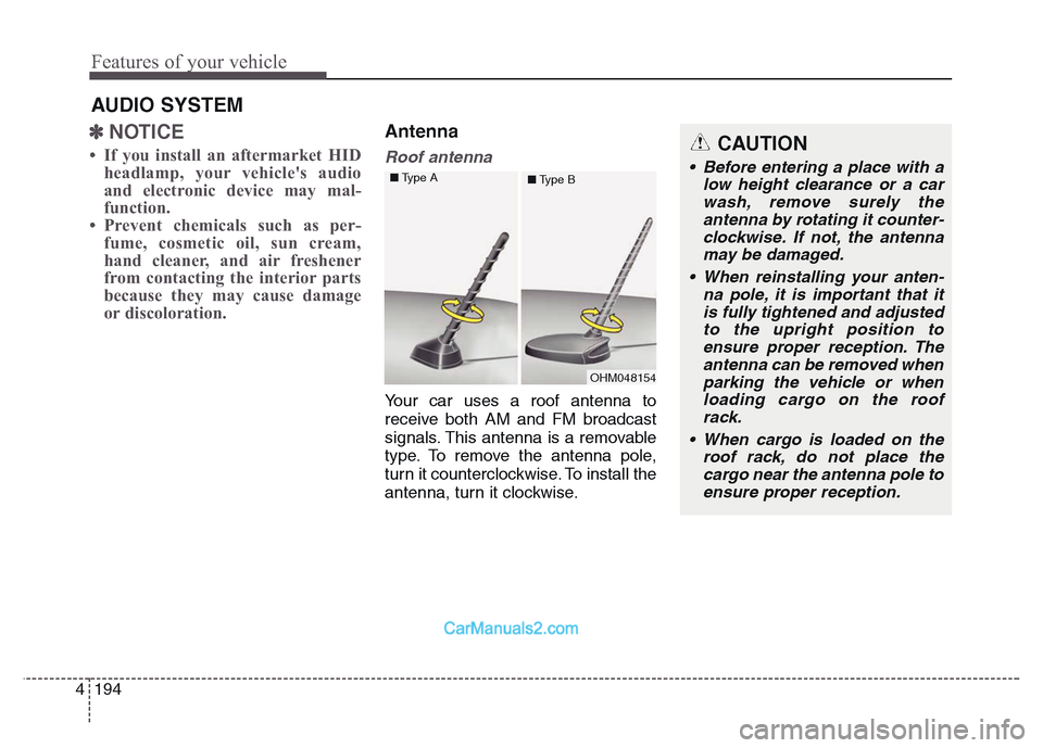
Your car uses a roof antenna to
receive both AM and FM broadcast
signals. This antenna is a removable
type. To remove the antenna pole,
turn it counterclockwise. To install the
antenna, turn it clockwise.
AUDIO SYSTEM
CAUTION
• Before entering a place with a
low height clearance or a car
wash, remove surely the
antenna by rotating it counter-
clockwise. If not, the antenna
may be damaged.
• When reinstalling your anten-
na pole, it is important that it
is fully tightened and adjusted
to the upright position to
ensure proper reception. The
antenna can be removed when
parking the vehicle or when
loading cargo on the roof
rack.
• When cargo is loaded on the
roof rack, do not place the
cargo near the antenna pole to
ensure proper reception.
OHM048154 ■Type A
■Type B