instrument cluster Hyundai Grandeur 2002 Owner's Manual
[x] Cancel search | Manufacturer: HYUNDAI, Model Year: 2002, Model line: Grandeur, Model: Hyundai Grandeur 2002Pages: 230, PDF Size: 3.82 MB
Page 10 of 230
YOUR VEHICLE AT A GLANCE
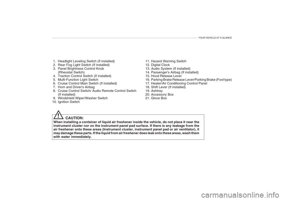
1. Headlight Leveling Switch (If installed)
2. Rear Fog Light Switch (If installed)
3. Panel Brightness Control Knob(Rheostat Switch)
4. Traction Control Switch (If installed)
5. Multi-Function Light Switch
6. Cruise Control Main Switch (If installed)
7. Horn and Driver's Airbag
8. Cruise Control Switch/ Audio Remote Control Switch
(If installed)
9. Windshield Wiper/Washer Switch
10. Ignition Switch
CAUTION:
When installing a container of liquid air freshener inside the vehicle, do not place it near theinstrument cluster nor on the instrument panel pad surface. If there is any leakage from the air freshener onto these areas (Instrument cluster, instrument panel pad or air ventilator), it may damage these parts. If the liquid from air freshener does leak onto these areas, wash themwith water immediately. 11. Hazard Warning Switch
12. Digital Clock
13. Audio System (If installed)
14. Passenger's Airbag (If installed)
15. Hood Release Lever
16. Parking Brake Release Lever/Parking Brake (Foot type)
17. Heater/Air Conditioning Control Panel
18. Shift Lever (If installed)
19. Ashtray
20. Accessory Box
21. Glove Box
!
Page 12 of 230
YOUR VEHICLE AT A GLANCE
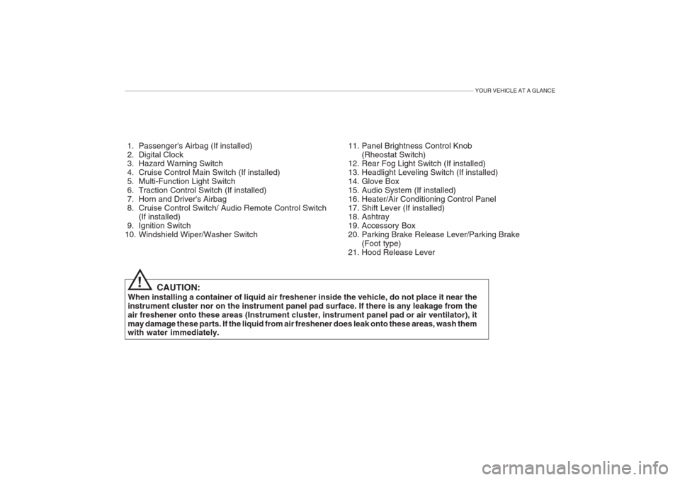
1. Passenger's Airbag (If installed)
2. Digital Clock
3. Hazard Warning Switch
4. Cruise Control Main Switch (If installed)
5. Multi-Function Light Switch
6. Traction Control Switch (If installed)
7. Horn and Driver's Airbag
8. Cruise Control Switch/ Audio Remote Control Switch(If installed)
9. Ignition Switch
10. Windshield Wiper/Washer Switch 11. Panel Brightness Control Knob
(Rheostat Switch)
12. Rear Fog Light Switch (If installed)
13. Headlight Leveling Switch (If installed)
14. Glove Box
15. Audio System (If installed)
16. Heater/Air Conditioning Control Panel
17. Shift Lever (If installed)
18. Ashtray
19. Accessory Box
20. Parking Brake Release Lever/Parking Brake
(Foot type)
21. Hood Release Lever
CAUTION:
When installing a container of liquid air freshener inside the vehicle, do not place it near theinstrument cluster nor on the instrument panel pad surface. If there is any leakage from theair freshener onto these areas (Instrument cluster, instrument panel pad or air ventilator), itmay damage these parts. If the liquid from air freshener does leak onto these areas, wash them with water immediately.
!
Page 14 of 230
1. FEATURES OF YOUR HYUNDAI
Fuel Recommendations .................................................................. 1-2
Breaking In Your New Hyundai ...................................................... 1-3
Key (Immobilizer System) ............................................................... 1-4
Door Locks (Theft-Alarm System) .................................................. 1-6
Power Windows ............................................................................1-10
Seat (Power Seat) ........................................................................ 1-11
I.M.S (Integrated Memory System) ............................................... 1-15
Seat Belt ....................................................................................... 1-18
Child Restraint System ................................................................. 1-23
Supplemental Restraint (AIRBAG) System .................................. 1-31
Instrument Cluster and Indicator Lights ........................................ 1-39
Warning Light and Indicator ......................................................... 1-41
Multi-function Light Switch ............................................................ 1-48
Windshield Wiper/Washer Switch .................................................1-50
Trip Computer ............................................................................... 1-53
Sunroof ......................................................................................... 1-57
Mirror ............................................................................................. 1-62
Hood Release ............................................................................... 1-68
Cruise Control ............................................................................... 1-72
Audio Rmote Control Switch ......................................................... 1-75
Heating and Cooling Control ........................................................ 1-76
Stereo Sound System ................................................................... 1-91
Audio Syste m ................................................................................ 1-93
Antenna ...................................................................................... 1-115
1
Page 48 of 230
FEATURES OF YOUR HYUNDAI 1- 35
B990A04Y-GAT PASSENGER PRESENCE DETECTION (If installed) The passenger presence detection system detects the presence of a pas-senger in the front seat. If no passen-ger is recognized on the front passen-ger seat, the deployment of the front passenger and/or side airbag and seat belt pretentioner will be inhibited.This system is designed primarily toprevent the replacement of airbag com-ponents that deploy needlessly in anaccident. NOTE: Luggage or other cargo heavier than 15 kg should not be placed on the passenger front seat. This can al-low the deployment of the frontpassenger and/or side air bag inthe case of an accident.
o The SRS can function only when
the ignition key is in the "ON"position. If the SRS SRI does notcome on, or continuously re-mains on, after flashing for about6 seconds when the ignition keyis turned to the "ON" position, or after the engine is started, comes on while driving, the SRS is notworking properly. If this occurs,have your vehicle immediatelyinspected by your Hyundaidealer.
o Before you replace a fuse or dis-
connect a battery terminal, turnthe ignition key to the "LOCK"position or remove the ignitionkey. Never remove or replace theair bag related fuse(s) when the ignition key is in the "ON" posi- tion. Failure to heed this warningwill cause the SRS SRI to illumi-nate.
WARNING:
o When the SRS is activated, there may be a loud noise and fine dustwill be released throughout thevehicle. These conditions arenormal and are not hazardous. However, the fine dust generated during airbag deployment maycause skin irritation. Wash yourhands and face thoroughly withlukewarm water and a mild soapafter an accident in which the airbags were deployed.
!
CAUTION:
When installing a container of liq- uid air freshener inside a vehicle, do not place it near the instrument cluster nor on the instrument panelpad surface. If there is any leakagefrom the air freshener onto theseareas (Instrument cluster, instru-ment panel pad or air ventilator), it may damage these parts. If the liq- uid from air freshener does leakonto these areas, wash them withwater immediately.!
Page 52 of 230
FEATURES OF YOUR HYUNDAI 1- 39
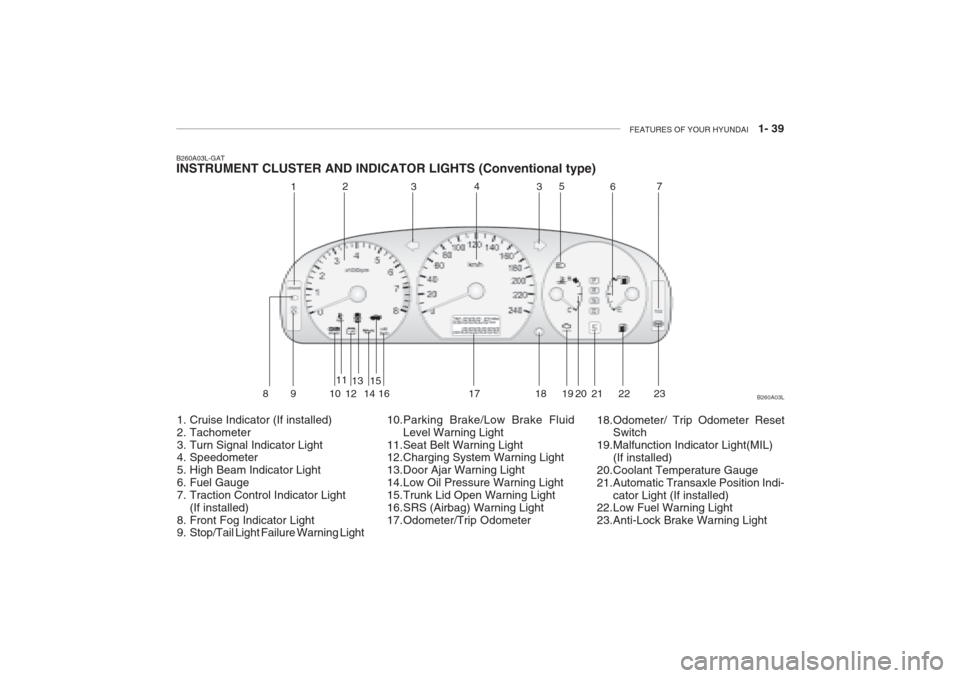
B260A03L-GAT INSTRUMENT CLUSTER AND INDICATOR LIGHTS (Conventional type)
1. Cruise Indicator (If installed)
2. Tachometer
3. Turn Signal Indicator Light
4. Speedometer
5. High Beam Indicator Light
6. Fuel Gauge
7. Traction Control Indicator Light (If installed)
8. Front Fog Indicator Light
9. Stop/Tail Light Failure Warning Light 10.Parking Brake/Low Brake Fluid
Level Warning Light
11.Seat Belt Warning Light
12.Charging System Warning Light
13.Door Ajar Warning Light
14.Low Oil Pressure Warning Light
15.Trunk Lid Open Warning Light
16.SRS (Airbag) Warning Light
17.Odometer/Trip Odometer 18.Odometer/ Trip Odometer Reset
Switch
19.Malfunction Indicator Light(MIL)
(If installed)
20.Coolant Temperature Gauge
21.Automatic Transaxle Position Indi-
cator Light (If installed)
22.Low Fuel Warning Light
23.Anti-Lock Brake Warning Light B260A03L
1
2
343
5
67
89 1 011
1213
1415
16 17 18 19 20 21 22
23
Page 53 of 230
1- 40 FEATURES OF YOUR HYUNDAI
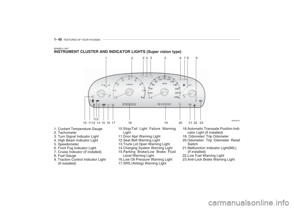
B260B01L-GAT INSTRUMENT CLUSTER AND INDICATOR LIGHTS (Super vision type)
1. Coolant Temperature Gauge
2. Tachometer
3. Turn Signal Indicator Light
4. High Beam Indicator Light
5. Speedometer
6. Front Fog Indicator Light
7. Cruise Indicator (If installed)
8. Fuel Gauge
9. Traction Control Indicator Light
(If installed) 10.Stop/Tail Light Failure Warning
Light
11.Door Ajar Warning Light
12.Seat Belt Warning Light
13.Trunk Lid Open Warning Light
14.Charging System Warning Light
15.Parking Brake/Low Brake Fluid Level Warning Light
16.Low Oil Pressure Warning Light
17.SRS (Airbag) Warning Light 18.Automatic Transaxle Position Indi-
cator Light (If installed)
19. Odometer/ Trip Odometer
20.Odometer/ Trip Odometer Reset Switch
21.Malfunction Indicator Light(MIL) (If installed)
22.Low Fuel Warning Light
23.Anti-Lock Brake Warning Light B260A04L
1
2
4
3 3
56 78
9
10 1112 13
14 15 16 17 18 19 20 21 22 23
Page 137 of 230
2- 8 DRIVING YOUR HYUNDAI
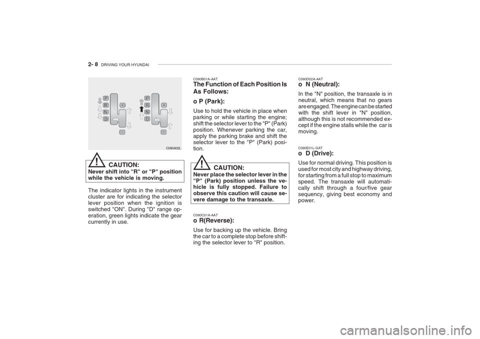
C090C01A-AAT o R(Reverse): Use for backing up the vehicle. Bring the car to a complete stop before shift- ing the selector lever to "R" position. C090D02A-AAT o N (Neutral): In the "N" position, the transaxle is in neutral, which means that no gearsare engaged. The engine can be startedwith the shift lever in "N" position,although this is not recommended ex- cept if the engine stalls while the car is moving.
C090E01L-GAT o D (Drive): Use for normal driving. This position is
used for most city and highway driving,for starting from a full stop to maximumspeed. The transaxle will automati-cally shift through a four/five gearsequency, giving best economy and power.
C090B01A-AAT The Function of Each Position Is As Follows: o P (Park): Use to hold the vehicle in place when parking or while starting the engine;shift the selector lever to the "P" (Park)position. Whenever parking the car,apply the parking brake and shift the selector lever to the "P" (Park) posi- tion.
CAUTION:
Never place the selector lever in the"P" (Park) position unless the ve- hicle is fully stopped. Failure to observe this caution will cause se-vere damage to the transaxle.
C090A02L
CAUTION:
Never shift into "R" or "P" positionwhile the vehicle is moving. The indicator lights in the instrument cluster are for indicating the selectorlever position when the ignition isswitched "ON". During "D" range op-eration, green lights indicate the gearcurrently in use.
!!
Page 141 of 230
2- 12 DRIVING YOUR HYUNDAI
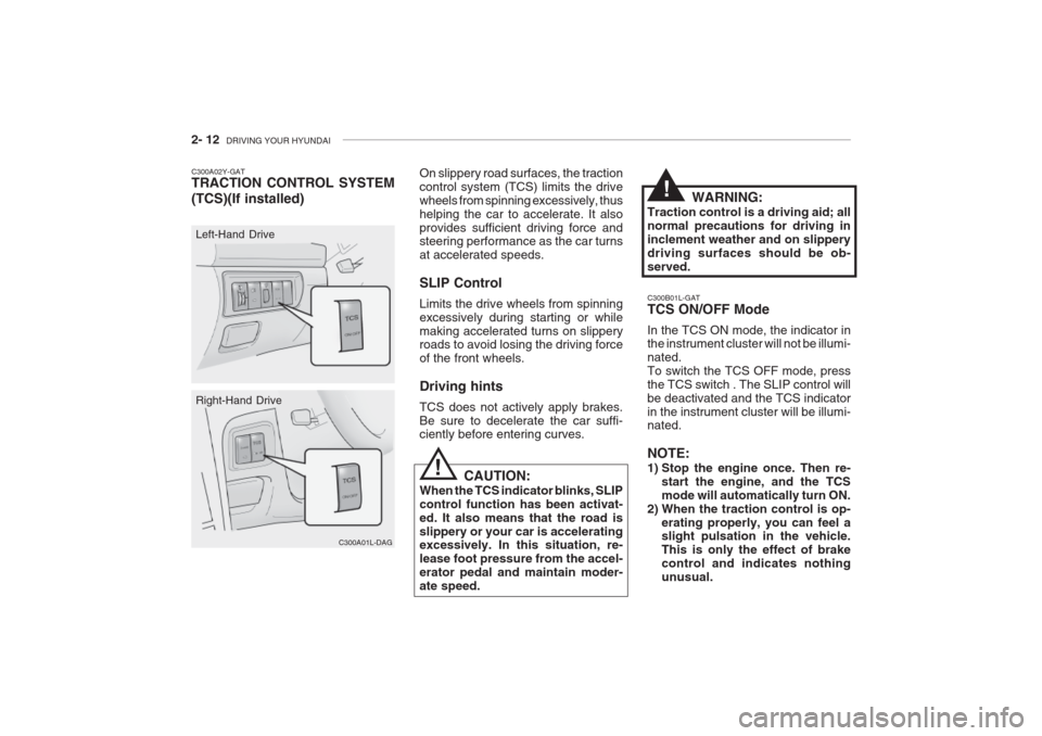
C300B01L-GAT TCS ON/OFF Mode In the TCS ON mode, the indicator in the instrument cluster will not be illumi- nated.To switch the TCS OFF mode, pressthe TCS switch . The SLIP control willbe deactivated and the TCS indicatorin the instrument cluster will be illumi- nated. NOTE:
1) Stop the engine once. Then re-
start the engine, and the TCS mode will automatically turn ON.
2) When the traction control is op- erating properly, you can feel a slight pulsation in the vehicle. This is only the effect of brakecontrol and indicates nothingunusual.
On slippery road surfaces, the tractioncontrol system (TCS) limits the drivewheels from spinning excessively, thushelping the car to accelerate. It alsoprovides sufficient driving force and steering performance as the car turns at accelerated speeds. SLIP Control Limits the drive wheels from spinning excessively during starting or whilemaking accelerated turns on slippery roads to avoid losing the driving force of the front wheels. Driving hints TCS does not actively apply brakes. Be sure to decelerate the car suffi- ciently before entering curves.
CAUTION:
When the TCS indicator blinks, SLIP control function has been activat-ed. It also means that the road isslippery or your car is accelerating excessively. In this situation, re- lease foot pressure from the accel-erator pedal and maintain moder-ate speed.
C300A01L-DAG
Right-Hand Drive
C300A02Y-GAT TRACTION CONTROL SYSTEM (TCS)(If installed)
C300A01L
Left-Hand Drive WARNING:
Traction control is a driving aid; all normal precautions for driving ininclement weather and on slipperydriving surfaces should be ob-served.
!
!
Page 212 of 230

DO-IT-YOURSELF MAINTENANCE 6- 35
FUSE RATING
25A 20A10A15A10A10A10A15A10A10A15A 10A 10A 10A20A10A 15A 10A15A10A10A15A10A20A 10A 10A 10A 10A10A10A 10A 10A PROTECTED COMPONENTS
Power seat
Seat warmerEPS controls
ETS relay
(HID) Head lights, DRL controls, AQS sensor
Blower & A/C controls
Turn & Hazard controlsNot used
Cruise switch, Instrument cluster
Head light leveling switch, Rain sensor, IMS controls
Rain sensor relay, Wiper & Washer controls
Home link connector, Left (Right) vanity lights, Sunroof, Blower & A/C controls,Electronic chrome mirrorNot used
Audio
Front (Rear) cigarette lighter, Accessory socket
IMS controls, Driver door module, RheostatNot used
Rear for light relay
Stop lights, Left (Right) personal lights, Left (Right) rear door lights
Door warning & Ignition key illumination, Courtesy lightsInstrument clusterSRS controls
Automatic transaxle controls, Back-up light switch, Vehicle speed sensor
Fuel filler door & Trunk lid opener, Driver (Assister) door module
Multipurpose check connector, Audio, lmmobiilizer controls, Trip computers, Digital
clock, Blower & A/C controls, Instrument cluster
Left (Right) inside lights, (HID) Head lights, Fog light relay, Right HID turn signal light,Right rear combination light
Stop light failure relay
Immobilizer controls, TCS switch, Trip computers, Instrument cluster
ETACM, Hazard switch, Auto light sensor
Antenna, Blower & A/C controls, Left (Right) outside mirror motor & Folding motor
(HID) Head lights, Front (Rear) cigarette lighters, Left (Right) license lights, Left HID
Turn signal light, Left rear combination lightBurglar alarm relay, Transaxle range switch, Start relay, ETS controlsDESCRIPTION P/SEAT
S/HTR EPSETS
H/LP
A/CON SW HAZARDSPARE
CRUISE IMS
WIPER
ETACS
SPARE AUDIO
C/LIGHTER MIRRORSPARE
RR FOG
STOP LP
ROOM LP
A/BAG IND A/BAGB/UP
T/LID
D/CLOCK
RH TAILSPARE
CLUSTER T/SIG
RR HTD IND
LH TAIL
START
G200D01L-GAT
Instrument Panel Junction Box
G200D01L
Page 228 of 230
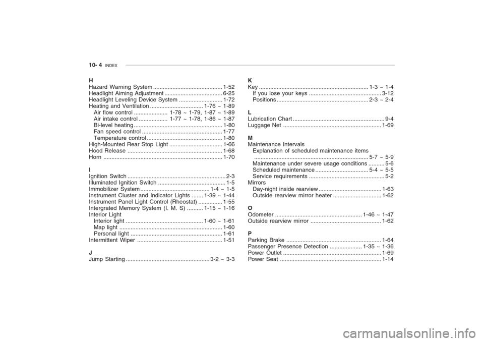
10- 4 INDEX
H Hazard Warning System........................................... 1-52
Headlight Aiming Adjustment .................................... 6-25
Headlight Leveling Device Syst em ...........................1-72
Heating and Ventilation ................................. 1-76 ~ 1-89
Air flow control ..................... 1-78 ~ 1-79, 1-87 ~ 1-89
Air intake control .................. 1-77 ~ 1-78, 1-86 ~ 1-87
Bi-level heating ....................................................... 1-80
Fan speed control .................................................. 1-77
Temperature control ............................................... 1-80
High-Mounted Rear Stop L ight .................................1-66
Hood Release ........................................................... 1-68
Horn .......................................................................... 1-70
I Ignition Switch ............................................................. 2-3
Illuminated Ignition Switch .......................................... 1-5 Immobilizer Sy stem ........................................... 1-4 ~ 1-5
Instrument Cluster and Indicator Lights ....... 1-39 ~ 1-44
Instrument Panel Light Control (Rheost at) ............... 1-55
Intergrated Memory System (I. M. S) .......... 1-15 ~ 1-16 Interior Light Interior light ................................................ 1-60 ~ 1-61
Map light ................................................................ 1-60
Personal light ......................................................... 1-61
Intermittent Wiper ..................................................... 1-51
J Jump Starting .................................................... 3-2 ~ 3-3 K
Key .................................................................... 1-3 ~ 1-4
If you lose your keys ............................................. 3-12
Positions ......................................................... 2-3 ~ 2-4
L Lubrication Chart ......................................................... 9-4
Luggage Net ............................................................. 1-69
MMaintenance Intervals Explanation of scheduled maintenance items....................................................................... 5-7 ~ 5-9
Maintenance under severe usage cond itions .......... 5-6
Scheduled maintenance ................................. 5-4 ~ 5-5
Service requ irements............................................... 5-2
Mirrors
Day-night inside rearview ....................................... 1-63
Outside rearview mirror heat er ..............................1-62
O
Odometer ...................................................... 1-46 ~ 1-47 Outside rearview mirror ............................................ 1-62
P Parking Brake ........................................................... 1-64
Passenger Presence Detec tion .................... 1-35 ~ 1-36
Power Outle t ............................................................. 1-69
Power Seat ............................................................... 1-14