Hyundai Grandeur 2003 Owner's Manual
Manufacturer: HYUNDAI, Model Year: 2003, Model line: Grandeur, Model: Hyundai Grandeur 2003Pages: 235, PDF Size: 14.25 MB
Page 201 of 235
6- 20 DO-IT-YOURSELF MAINTENANCE
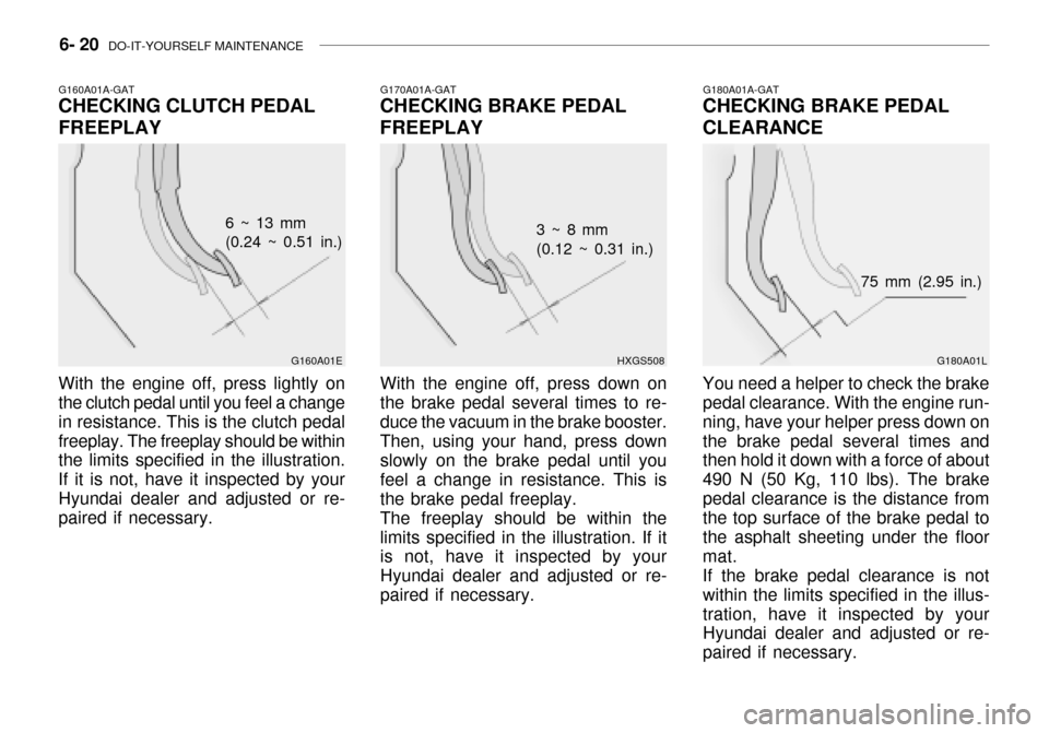
G180A01A-GAT
CHECKING BRAKE PEDAL CLEARANCE
G180A01L
75 mm (2.95 in.)
You need a helper to check the brake pedal clearance. With the engine run- ning, have your helper press down onthe brake pedal several times and then hold it down with a force of about 490 N (50 Kg, 110 lbs). The brakepedal clearance is the distance from the top surface of the brake pedal to the asphalt sheeting under the floormat.If the brake pedal clearance is notwithin the limits specified in the illus-tration, have it inspected by your Hyundai dealer and adjusted or re- paired if necessary.G170A01A-GAT
CHECKING BRAKE PEDAL FREEPLAY
HXGS508
3 ~ 8 mm (0.12 ~ 0.31 in.)
With the engine off, press down onthe brake pedal several times to re- duce the vacuum in the brake booster. Then, using your hand, press down slowly on the brake pedal until you feel a change in resistance. This isthe brake pedal freeplay.The freeplay should be within thelimits specified in the illustration. If it is not, have it inspected by your Hyundai dealer and adjusted or re-paired if necessary.G160A01A-GAT CHECKING CLUTCH PEDAL FREEPLAY
G160A01E
6 ~ 13 mm (0.24 ~ 0.51 in.)
With the engine off, press lightly onthe clutch pedal until you feel a change in resistance. This is the clutch pedalfreeplay. The freeplay should be within the limits specified in the illustration. If it is not, have it inspected by yourHyundai dealer and adjusted or re- paired if necessary.
Page 202 of 235
DO-IT-YOURSELF MAINTENANCE 6- 21
G190A01A-GAT
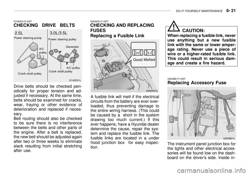
CHECKING DRIVE BELTS
Drive belts should be checked peri- odically for proper tension and ad- justed if necessary. At the same time, belts should be examined for cracks,wear, fraying or other evidence of deterioration and replaced if neces- sary. Belt routing should also be checked to be sure there is no interference between the belts and other parts ofthe engine. After a belt is replaced, the new belt should be adjusted again after two or three weeks to eliminateslack resulting from initial stretching after use. G140D01L
2.5L
3.0L/3.5L
Power steering pump
Crank shaft pulley A/C pulley
Crank shaft pulley
A/C pulley
Power steering pulley
Generator
G200A01Y-GAT
CHECKING AND REPLACING FUSES Replacing a Fusible Link
A fusible link will melt if the electrical circuits from the battery are ever over- loaded, thus preventing damage tothe entire wiring harness. (This could be caused by a short in the system drawing too much current.) If thisever happens, have a Hyundai dealer determine the cause, repair the sys- tem and replace the fusible link. Thefusible links are located in a under hood junction box for easy inspec- tion. G200A01L
Melted
Good
G200B01Y-GAT Replacing Accessory Fuse
G200B01L
The instrument panel junction box for
the lights and other electrical acces- sories will be found low on the dash- board on the driver's side. Inside in- CAUTION:
When replacing a fusible link, never use anything but a new fusiblelink with the same or lower amper- age rating. Never use a piece of wire or a higher-rated fusible link.This could result in serious dam- age and create a fire hazard.
!
Page 203 of 235
6- 22 DO-IT-YOURSELF MAINTENANCE
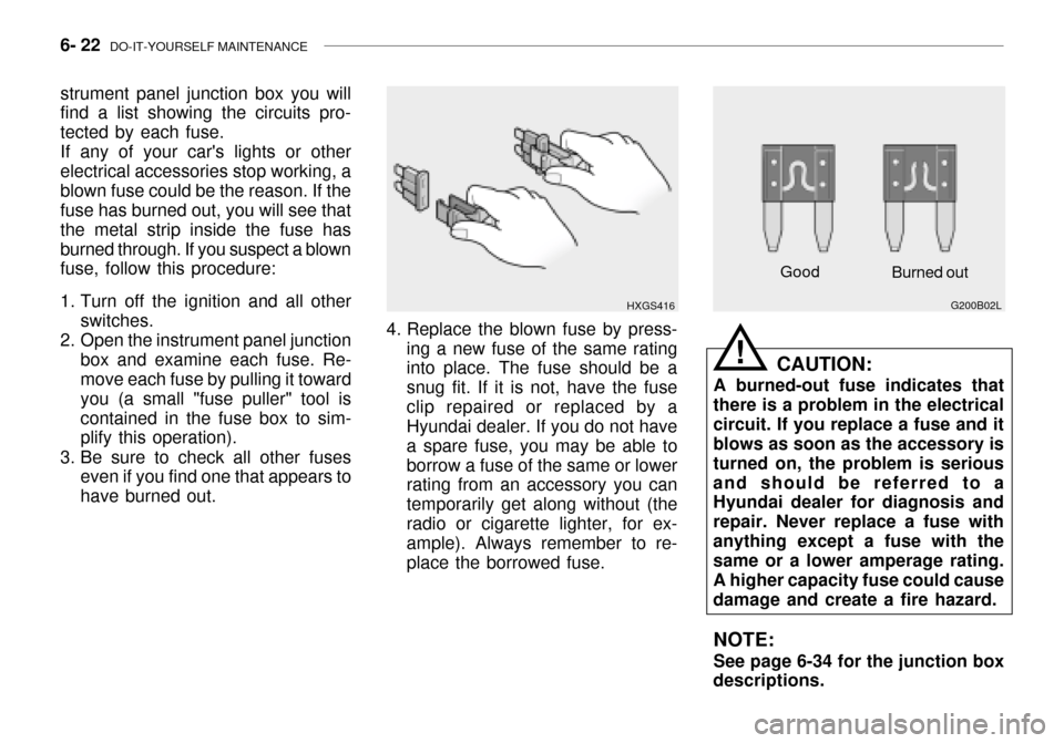
Good
G200B02L
Burned out
CAUTION:
A burned-out fuse indicates that
there is a problem in the electrical circuit. If you replace a fuse and it blows as soon as the accessory is turned on, the problem is seriousand should be referred to a Hyundai dealer for diagnosis and repair. Never replace a fuse withanything except a fuse with the same or a lower amperage rating. A higher capacity fuse could causedamage and create a fire hazard.
NOTE: See page 6-34 for the junction box
descriptions.
!
strument panel junction box you will find a list showing the circuits pro- tected by each fuse.
If any of your car's lights or other
electrical accessories stop working, ablown fuse could be the reason. If the fuse has burned out, you will see that the metal strip inside the fuse hasburned through. If you suspect a blown fuse, follow this procedure:
1. Turn off the ignition and all other switches.
2. Open the instrument panel junction box and examine each fuse. Re- move each fuse by pulling it toward you (a small "fuse puller" tool iscontained in the fuse box to sim- plify this operation).
3. Be sure to check all other fuses even if you find one that appears to have burned out.
HXGS416
4. Replace the blown fuse by press- ing a new fuse of the same rating into place. The fuse should be a snug fit. If it is not, have the fuseclip repaired or replaced by a Hyundai dealer. If you do not have a spare fuse, you may be able toborrow a fuse of the same or lower rating from an accessory you can temporarily get along without (theradio or cigarette lighter, for ex- ample). Always remember to re- place the borrowed fuse.
Page 204 of 235

DO-IT-YOURSELF MAINTENANCE 6- 23
G210A01A-AAT
CHECKING THE BATTERY
WARNING:
Batteries can be dangerous! When working with batteries, care-
fully observe the following pre- cautions to avoid serious injuries.
The fluid in the battery contains a
strong solution of sulfuric acid, whichis poisonous and highly corrosive. Be careful not to spill it on yourself or thecar. If you do spill battery fluid on yourself, immediately do the follow- ing:
o If battery fluid is on your skin, flush the affected areas with water for at least 15 minutes and then seek medical assistance.
o If battery fluid is in your eyes, rinse out your eyes with water and getmedical assistance as soon as possible. While you are being driven to get medical assistance, continueto rinse your eyes by using a sponge or soft cloth saturated with water. o If you swallow battery fluid, drink a
large quantity of water or milk fol-lowed by milk of magnesia, eat araw egg or drink vegetable oil. Get medical assistance as soon as pos- sible.
While batteries are being charged(either by a battery charger or by the vehicle's generator), they produce explosive gases. Always observethese warnings to prevent injuries from occurring:
o Charge batteries only in a well ven- tilated area.
o Do not permit flames, sparks or smoking in the area.
o Keep children away from the area. G210B01A-AAT Checking the Battery Keep the battery clean. Any evidence of corrosion around the battery posts or terminals should be removed using a solution of household baking sodaand warm water. After the battery terminals are dry, cover them with a light coating of grease.
!
G220A01A-AAT
CHECKING ELECTRIC COOL- ING FANS
WARNING:
The cooling fan is controlled by
engine coolant temperature and may sometimes operate even whenthe engine is not running. Use extreme caution when working near the blades of the cooling fan,so that you are not injured by a rotating fan blade. As the coolant temperature decreases the fan willautomatically shut off. This is a normal condition.
G220B01A-AAT
Checking Engine Cooling Fan
The engine cooling fan should come
on automatically if the engine coolanttemperature is high.
G220C01A-AAT
Checking Condenser Cooling Fan
The condenser cooling fan should
come on automatically whenever the air conditioning is in operation.
!
Page 205 of 235
6- 24 DO-IT-YOURSELF MAINTENANCE
G240A01A-AAT
POWER STEERING HOSES
It is suggested that you check the power steering hose connections forfluid leakage at regular intervals.The power steering hoses should bereplaced if there is severe surface cracking, scuffing or worn spots. De- terioration of the hose could causepremature failure.
G230A03A-GAT POWER STEERING FLUID LEVEL
HXG2006
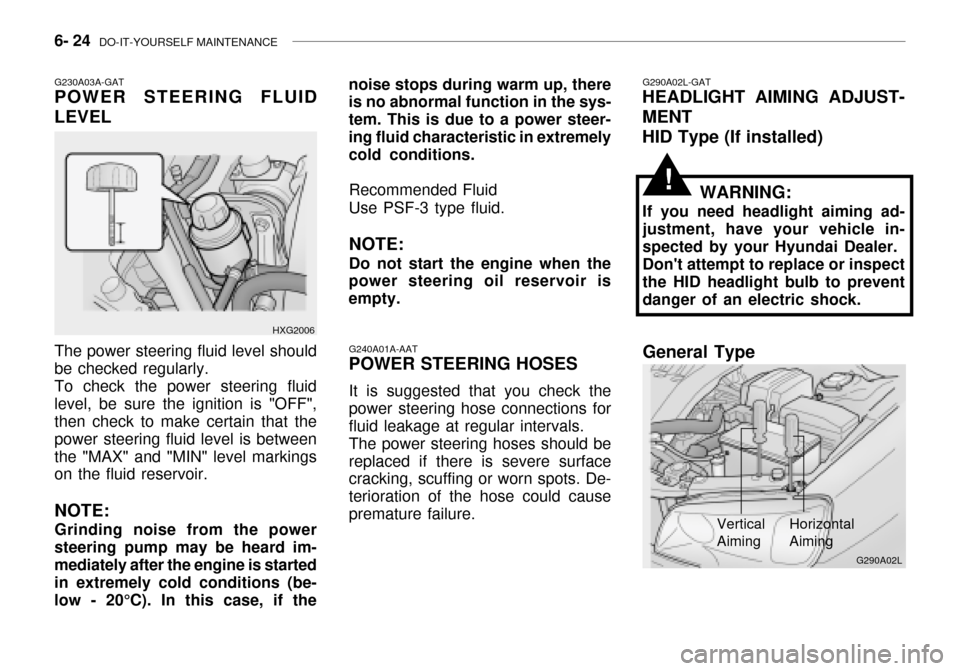
The power steering fluid level should be checked regularly. To check the power steering fluid level, be sure the ignition is "OFF", then check to make certain that the power steering fluid level is betweenthe "MAX" and "MIN" level markings on the fluid reservoir. NOTE: Grinding noise from the power steering pump may be heard im-mediately after the engine is started in extremely cold conditions (be- low - 20°C). In this case, if the noise stops during warm up, there is no abnormal function in the sys- tem. This is due to a power steer-ing fluid characteristic in extremely cold conditions.
Recommended Fluid Use PSF-3 type fluid. NOTE: Do not start the engine when the
power steering oil reservoir is empty.
G290A02L-GAT
HEADLIGHT AIMING ADJUST- MENT
HID Type (If installed)
WARNING:
If you need headlight aiming ad- justment, have your vehicle in- spected by your Hyundai Dealer. Don't attempt to replace or inspect the HID headlight bulb to prevent danger of an electric shock.
Vertical Aiming HorizontalAiming
!
G290A02L
General Type
Page 206 of 235
DO-IT-YOURSELF MAINTENANCE 6- 25
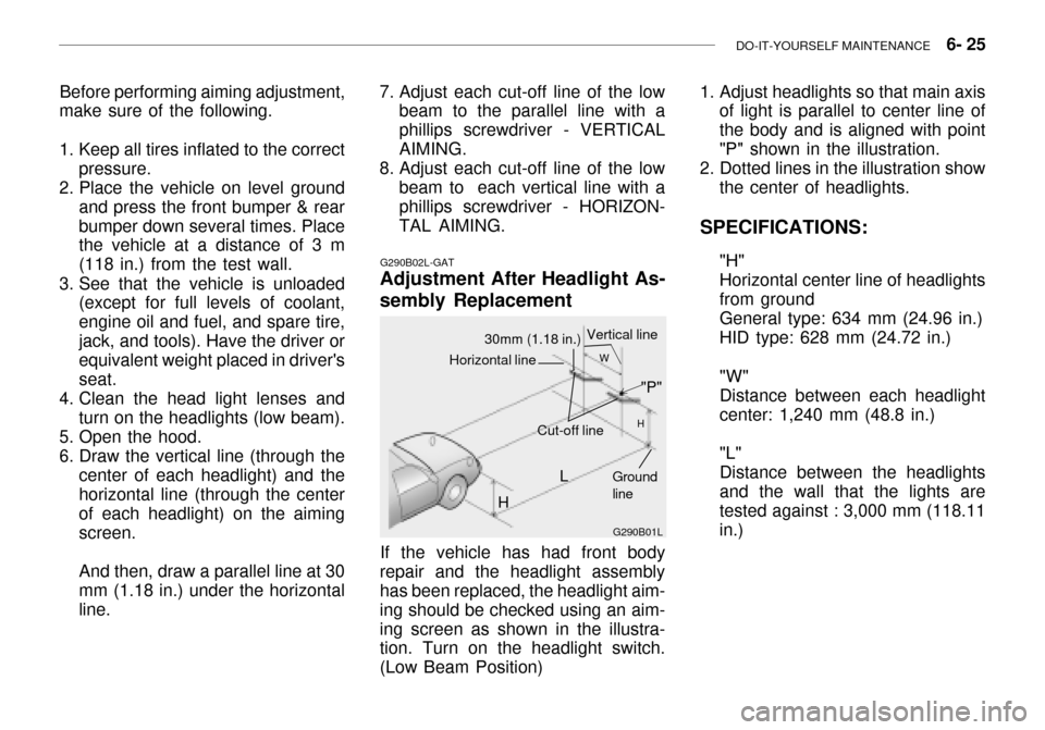
Before performing aiming adjustment,
make sure of the following.
1. Keep all tires inflated to the correct
pressure.
2. Place the vehicle on level ground
and press the front bumper & rear bumper down several times. Place the vehicle at a distance of 3 m (118 in.) from the test wall.
3. See that the vehicle is unloaded (except for full levels of coolant,engine oil and fuel, and spare tire,jack, and tools). Have the driver or equivalent weight placed in driver's seat.
4. Clean the head light lenses and
turn on the headlights (low beam).
5. Open the hood.
6. Draw the vertical line (through the center of each headlight) and the horizontal line (through the center of each headlight) on the aimingscreen. And then, draw a parallel line at 30 mm (1.18 in.) under the horizontal line.
G290B02L-GAT
Adjustment After Headlight As- sembly Replacement
G290B01L
LW
H
H Cut-off line
Ground line
If the vehicle has had front body
repair and the headlight assembly has been replaced, the headlight aim- ing should be checked using an aim-ing screen as shown in the illustra- tion. Turn on the headlight switch. (Low Beam Position)
"P"
Horizontal line
30mm (1.18 in.) Vertical line
7. Adjust each cut-off line of the low
beam to the parallel line with a phillips screwdriver - VERTICALAIMING.
8. Adjust each cut-off line of the low
beam to each vertical line with a phillips screwdriver - HORIZON- TAL AIMING. 1. Adjust headlights so that main axis
of light is parallel to center line ofthe body and is aligned with point"P" shown in the illustration.
2. Dotted lines in the illustration show the center of headlights.
SPECIFICATIONS: "H"Horizontal center line of headlightsfrom groundGeneral type: 634 mm (24.96 in.) HID type: 628 mm (24.72 in.) "W" Distance between each headlightcenter: 1,240 mm (48.8 in.) "L" Distance between the headlightsand the wall that the lights aretested against : 3,000 mm (118.11 in.)
Page 207 of 235
6- 26 DO-IT-YOURSELF MAINTENANCE
G260A01L-GAT
REPLACEMENT OF LIGHT BULBS
Before attempting to replace a light bulb, be sure the switch is turned tothe "OFF" position.The next paragraph shows how toreach the light bulbs so they may be changed. Be sure to replace the burned-out bulb with one of the samenumber and wattage rating.See page 6-33 for the wattage de-scriptions.
! CAUTION:
o Keep the lights out of contact with petroleum products, such as oil, gasoline, etc.
o Be sure to replace the LED type equipped bulbs with an assem-bly.Replacement instructions:
1. Allow the bulb to cool. Wear eye protection.
2. Open the engine hood.
3. Always grasp the bulb by its plastic base, avoid touching the glass. G270A03L
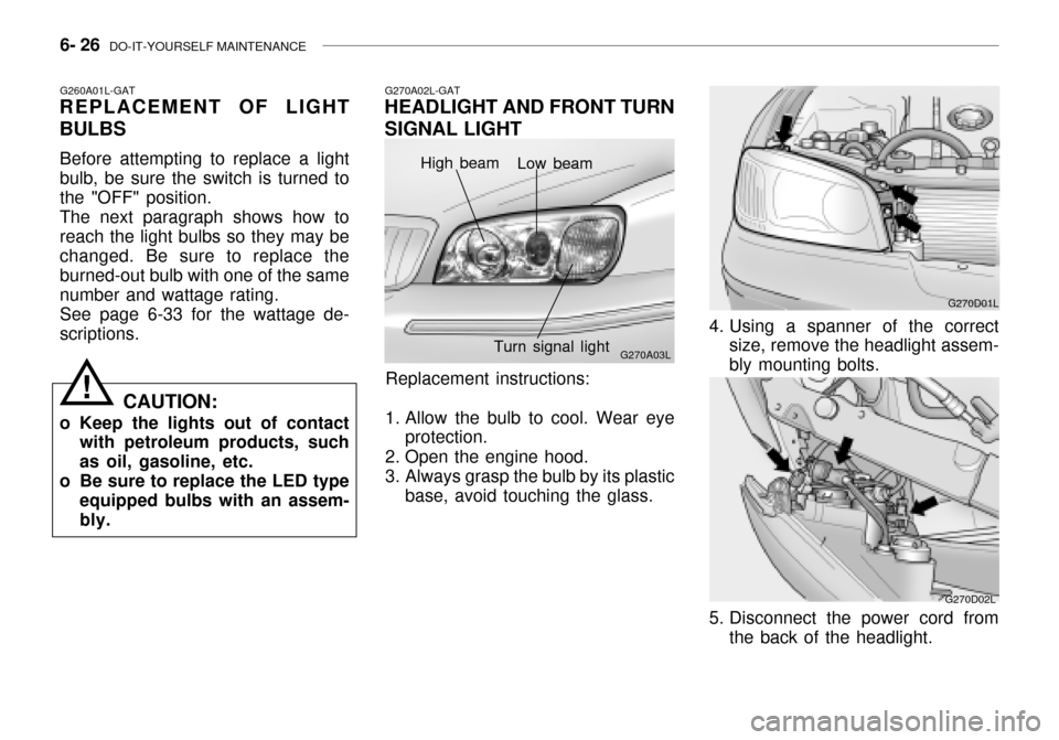
G270A02L-GAT
HEADLIGHT AND FRONT TURN SIGNAL LIGHT
High beam Low beam
Turn signal light
G270D01L
4. Using a spanner of the correct size, remove the headlight assem- bly mounting bolts.
G270D02L
5. Disconnect the power cord from the back of the headlight.
Page 208 of 235
DO-IT-YOURSELF MAINTENANCE 6- 27
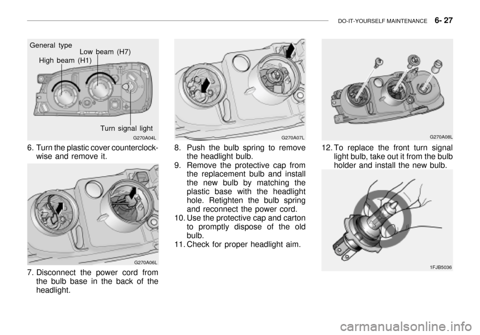
G270A04L
General type
High beam (H1)
Low beam (H7)
Turn signal light
6. Turn the plastic cover counterclock- wise and remove it.
G270A06L
7. Disconnect the power cord from the bulb base in the back of the headlight.
G270A07L
8. Push the bulb spring to remove the headlight bulb.
9. Remove the protective cap from the replacement bulb and install the new bulb by matching theplastic base with the headlight hole. Retighten the bulb spring and reconnect the power cord.
10. Use the protective cap and carton to promptly dispose of the oldbulb.
11. Check for proper headlight aim.
12. To replace the front turn signal light bulb, take out it from the bulb holder and install the new bulb. G270A08L
1FJB5036
Page 209 of 235
6- 28 DO-IT-YOURSELF MAINTENANCE
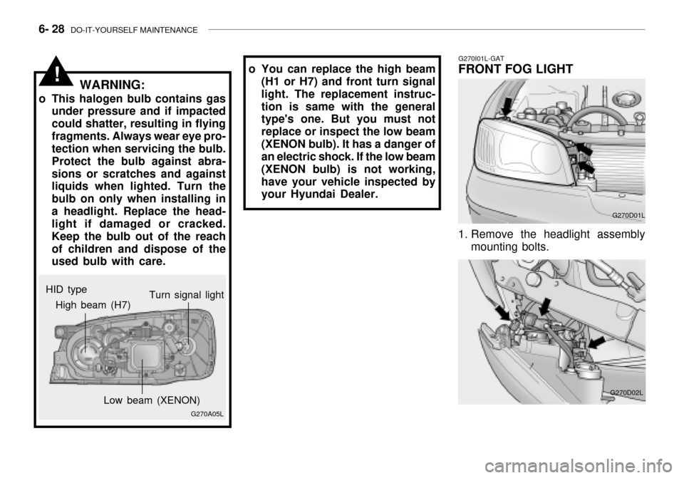
G270I01L-GAT
FRONT FOG LIGHT
G270D01L
1. Remove the headlight assembly mounting bolts.
G270D02L
HID type
!
G270A05L
High beam (H7)
Low beam (XENON)Turn signal light
WARNING:
o This halogen bulb contains gas under pressure and if impacted could shatter, resulting in flyingfragments. Always wear eye pro- tection when servicing the bulb. Protect the bulb against abra-sions or scratches and against liquids when lighted. Turn the bulb on only when installing ina headlight. Replace the head- light if damaged or cracked. Keep the bulb out of the reachof children and dispose of the used bulb with care. o You can replace the high beam
(H1 or H7) and front turn signal light. The replacement instruc-tion is same with the general type's one. But you must not replace or inspect the low beam(XENON bulb). It has a danger of an electric shock. If the low beam (XENON bulb) is not working,have your vehicle inspected by your Hyundai Dealer.
Page 210 of 235
DO-IT-YOURSELF MAINTENANCE 6- 29
G270D03L
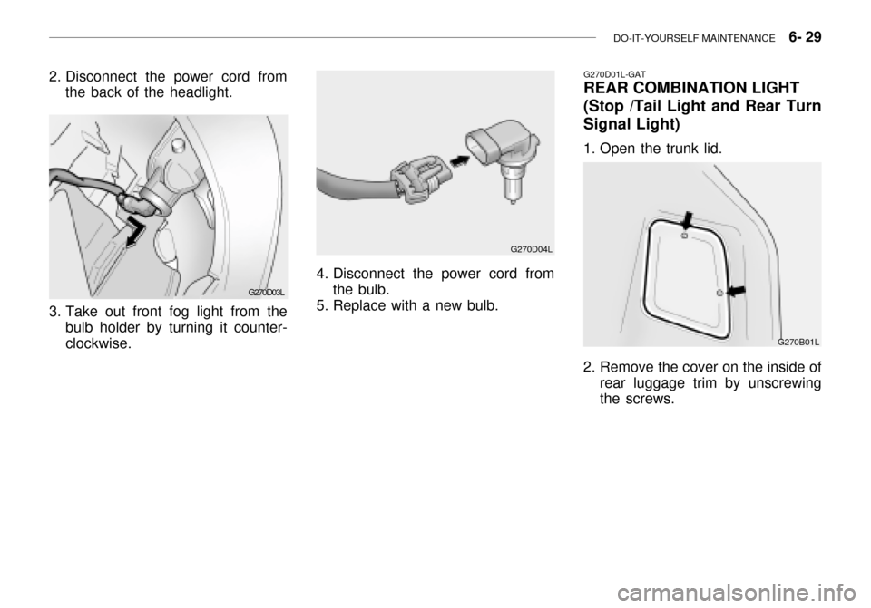
2. Disconnect the power cord from
the back of the headlight.
3. Take out front fog light from the bulb holder by turning it counter- clockwise.
4. Disconnect the power cord fromthe bulb.
5. Replace with a new bulb. G270D04L
G270D01L-GAT
REAR COMBINATION LIGHT
(Stop /Tail Light and Rear Turn Signal Light)
1. Open the trunk lid.
2. Remove the cover on the inside of
rear luggage trim by unscrewing the screws. G270B01L