low beam Hyundai Grandeur 2004 Owner's Manual
[x] Cancel search | Manufacturer: HYUNDAI, Model Year: 2004, Model line: Grandeur, Model: Hyundai Grandeur 2004Pages: 235, PDF Size: 6.64 MB
Page 13 of 235

YOUR VEHICLE AT A GLANCE
Turn Signal Indicator Lights ABS Service Reminder Indicator Traction Control Indicator Light Seat Belt Warning LightHigh Beam Indicator Light Trunk Lid Open Warning Light Front Fog Indicator LightLow Oil Pressure Warning LightParking Brake/Low Brake Fluid Level Warning Light Charging System Warning Light Door Ajar Warning Light and Chime Low Fuel Level Warning Light SRS (Airbag) Service Reminder Indicator Cruise Indicator Light Stop/Tail Light Failure Warning Light Malfunction Indicator Light
B255A01L-GAT INDICATOR SYMBOLS ON THE INSTRUMENT PANEL * More detailed explanations of these items will be found beginning on page 1-43
Page 54 of 235
FEATURES OF YOUR HYUNDAI 1- 41
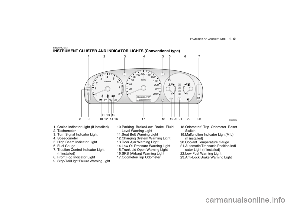
B260A03L-GAT INSTRUMENT CLUSTER AND INDICATOR LIGHTS (Conventional type)
1. Cruise Indicator Light (If installed)
2. Tachometer
3. Turn Signal Indicator Light
4. Speedometer
5. High Beam Indicator Light
6. Fuel Gauge
7. Traction Control Indicator Light (If installed)
8. Front Fog Indicator Light
9. Stop/Tail Light Failure Warning Light 10.Parking Brake/Low Brake Fluid
Level Warning Light
11.Seat Belt Warning Light
12.Charging System Warning Light
13.Door Ajar Warning Light
14.Low Oil Pressure Warning Light
15.Trunk Lid Open Warning Light
16.SRS (Airbag) Warning Light
17.Odometer/Trip Odometer 18.Odometer/ Trip Odometer Reset
Switch
19.Malfunction Indicator Light(MIL)
(If installed)
20.Coolant Temperature Gauge
21.Automatic Transaxle Position Indi-
cator Light (If installed)
22.Low Fuel Warning Light
23.Anti-Lock Brake Warning Light B260A03L
1
2
3435
67
89 1 011
1213
1415
16 17 18 19 20 21 22
23
Page 55 of 235
1- 42 FEATURES OF YOUR HYUNDAI
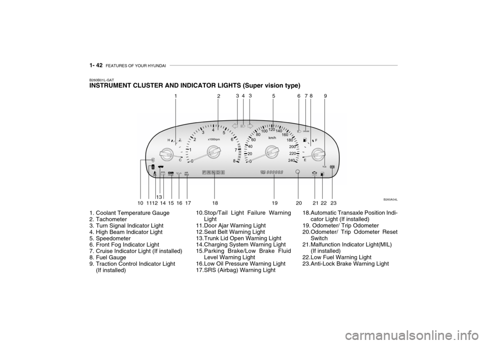
B260B01L-GAT INSTRUMENT CLUSTER AND INDICATOR LIGHTS (Super vision type)
1. Coolant Temperature Gauge
2. Tachometer
3. Turn Signal Indicator Light
4. High Beam Indicator Light
5. Speedometer
6. Front Fog Indicator Light
7. Cruise Indicator Light (If installed)
8. Fuel Gauge
9. Traction Control Indicator Light
(If installed) 10.Stop/Tail Light Failure Warning
Light
11.Door Ajar Warning Light
12.Seat Belt Warning Light
13.Trunk Lid Open Warning Light
14.Charging System Warning Light
15.Parking Brake/Low Brake Fluid
Level Warning Light
16.Low Oil Pressure Warning Light
17.SRS (Airbag) Warning Light 18.Automatic Transaxle Position Indi-
cator Light (If installed)
19. Odometer/ Trip Odometer
20.Odometer/ Trip Odometer Reset
Switch
21.Malfunction Indicator Light(MIL)
(If installed)
22.Low Fuel Warning Light
23.Anti-Lock Brake Warning Light B260A04L
1
2
4
3 3
56 78
9
10 1112 13
14 15 16 17 18 19 20 21 22 23
Page 64 of 235

FEATURES OF YOUR HYUNDAI 1- 51
B340F01L-GAT Auto Light
3A9CA44
To operate the automatic light feature, turn the barrel on the end of the multi- function switch. If you set the multi- function switch to "AUTO", the taillights and headlights will be turned automatically on or off according to external illumination. B340D01A-AAT High-beam Switch To turn on the headlight high beams, push the lever forward (away from you). The High Beam Indicator Light will come on at the same time. For lowbeams, pull the lever back toward you.
HHP268
B340F01A-GAT Daytime Running Lights (If Installed) Your Hyundai is equipped with day- time running lights. The daytime run- ning lights are used to improve visibil-ity for oncoming traffic. Your vehicle daytime running lights are designed to remain on continuously when the en-gine is operating even though the head- light switch is in the "OFF" position. However, the daytime running lightswill be off while the parking brake is applied.
To turn them "ON" again you mustsimply turn the ignition key to the "ON" position.
Page 88 of 235
FEATURES OF YOUR HYUNDAI 1- 75
B600B01L-GAT STEERING WHEEL ELECTRIC TILT AND TELESCOPIC
(If Installed)
HXGS262
To adjust the desired position of the steering wheel, operate the adjusting switch on the left side of the steeringwheel.
WARNING:
Do not attempt to adjust the steer-ing wheel while driving as this mayresult in loss of control of the ve- hicle and serious injury or death.
!
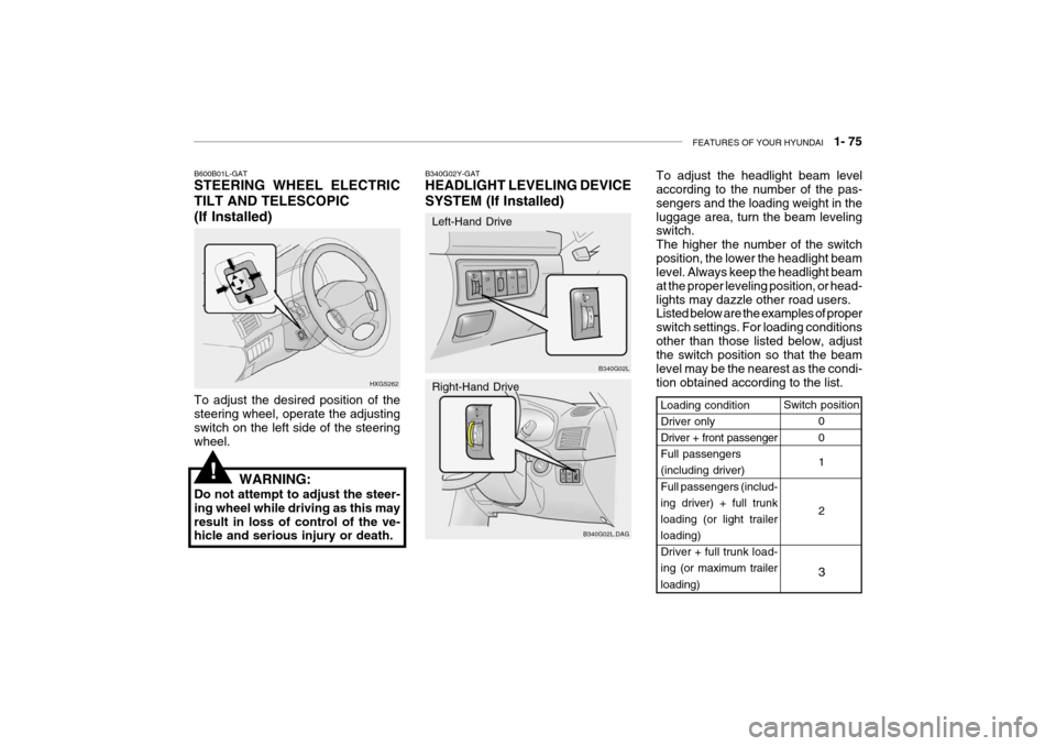
Switch position
0 0 1 2
3Loading condition Driver only Driver + front passenger Full passengers(including driver) Full passengers (includ- ing driver) + full trunkloading (or light trailer loading)
Driver + full trunk load-ing (or maximum trailer
loading)
B340G02L
B340G02L.DAG
B340G02Y-GAT HEADLIGHT LEVELING DEVICE
SYSTEM (If Installed)
Left-Hand Drive Right-Hand Drive
To adjust the headlight beam level according to the number of the pas- sengers and the loading weight in theluggage area, turn the beam leveling switch. The higher the number of the switchposition, the lower the headlight beam level. Always keep the headlight beam at the proper leveling position, or head-lights may dazzle other road users. Listed below are the examples of proper switch settings. For loading conditionsother than those listed below, adjust the switch position so that the beam level may be the nearest as the condi-tion obtained according to the list.
Page 151 of 235

2- 18 DRIVING YOUR HYUNDAI
C180A01A-AAT USE OF LIGHTS Check your lights regularly for correct operation and always keep them clean.When driving during the day in condi- tions of poor visibility, it is helpful to drive with headlights on low beam.This enables you to be seen as well as to see.
C190A01A-GAT TRAILER OR VEHICLE TOWING If you are considering towing with your car, you should first check with your Province Department of Motor Vehicles
to determine their legal requirements.Since laws vary from province to prov- ince the requirements for towing trail- ers, cars, or other types of vehicles orapparatus may differ. Ask your Hyundai dealer for further details before towing.
C170A01A-AAT HIGH SPEED MOTORING Pre-Trip Inspections 1. Tires: Adjust the tire inflation pressures to specification. Low tire inflation pres-sures will result in overheating and possible failure of the tires. Avoid using worn or damaged tireswhich may result in reduced traction or tire failure. NOTE: Never exceed the maximum tire in- flation pressure shown on the tires. 2. Fuel, engine coolant and engine oil: High speed travel consumes more fuel than urban motoring. Do not forget tocheck both engine coolant and engine oil. 3. Drive belt: A loose or damaged drive belt may result in overheating of the engine.
C160K01A-AAT Carry Emergency Equipment Depending on the severity of the weather where you drive your car, you should carry appropriate emergency equipment. Some of the items youmay want to carry include tire chains, tow straps or chains, flashlight, emer- gency flares, sand, a shovel, jumpercables, a window scraper, gloves, ground cloth, coveralls, a blanket, etc.
C160J01A-AAT Don't Let Ice and Snow Accumu- late Underneath Under some conditions, snow and ice can build up under the fenders and interfere with the steering. When driv-ing in severe winter conditions where this may happen, you should periodi- cally check underneath the car to besure the movement of the front wheels and the steering components is not obstructed.
Page 207 of 235
DO-IT-YOURSELF MAINTENANCE 6- 25
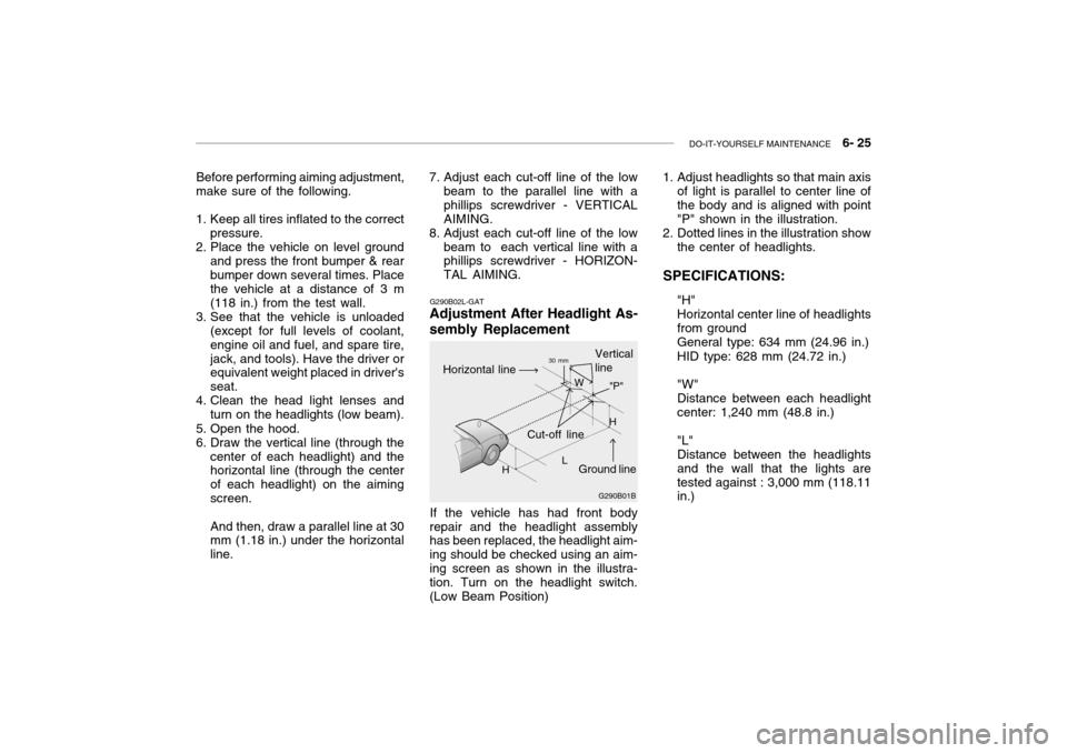
Before performing aiming adjustment,
make sure of the following.
1. Keep all tires inflated to the correct
pressure.
2. Place the vehicle on level ground
and press the front bumper & rear bumper down several times. Place the vehicle at a distance of 3 m (118 in.) from the test wall.
3. See that the vehicle is unloaded (except for full levels of coolant,engine oil and fuel, and spare tire,jack, and tools). Have the driver or equivalent weight placed in driver's seat.
4. Clean the head light lenses and
turn on the headlights (low beam).
5. Open the hood.
6. Draw the vertical line (through the center of each headlight) and the horizontal line (through the center of each headlight) on the aimingscreen. And then, draw a parallel line at 30 mm (1.18 in.) under the horizontal line. G290B02L-GAT
Adjustment After Headlight As- sembly Replacement
If the vehicle has had front body
repair and the headlight assembly has been replaced, the headlight aim- ing should be checked using an aim-ing screen as shown in the illustra- tion. Turn on the headlight switch. (Low Beam Position)
7. Adjust each cut-off line of the low
beam to the parallel line with aphillips screwdriver - VERTICALAIMING.
8. Adjust each cut-off line of the low
beam to each vertical line with a phillips screwdriver - HORIZON- TAL AIMING. 1. Adjust headlights so that main axis
of light is parallel to center line ofthe body and is aligned with point"P" shown in the illustration.
2. Dotted lines in the illustration show
the center of headlights.
SPECIFICATIONS: "H"Horizontal center line of headlightsfrom groundGeneral type: 634 mm (24.96 in.) HID type: 628 mm (24.72 in.) "W" Distance between each headlightcenter: 1,240 mm (48.8 in.) "L" Distance between the headlightsand the wall that the lights aretested against : 3,000 mm (118.11 in.)
G290B01B
L W
Cut-off line Ground line
"P"
Horizontal line
Vertical line30 mm
H H
Page 208 of 235
6- 26 DO-IT-YOURSELF MAINTENANCE
G260A01L-GAT
REPLACEMENT OF LIGHT BULBS
Before attempting to replace a light bulb, be sure the switch is turned tothe "OFF" position.The next paragraph shows how toreach the light bulbs so they may be changed. Be sure to replace the burned-out bulb with one of the samenumber and wattage rating.See page 6-33 for the wattage de-scriptions.
! CAUTION:
o Keep the lights out of contact with petroleum products, such as oil, gasoline, etc.
o Be sure to replace the LED type equipped bulbs with an assem-bly.Replacement instructions:
1. Allow the bulb to cool. Wear eye protection.
2. Open the engine hood.
3. Always grasp the bulb by its plastic base, avoid touching the glass. G270A03L
G270A02L-GAT
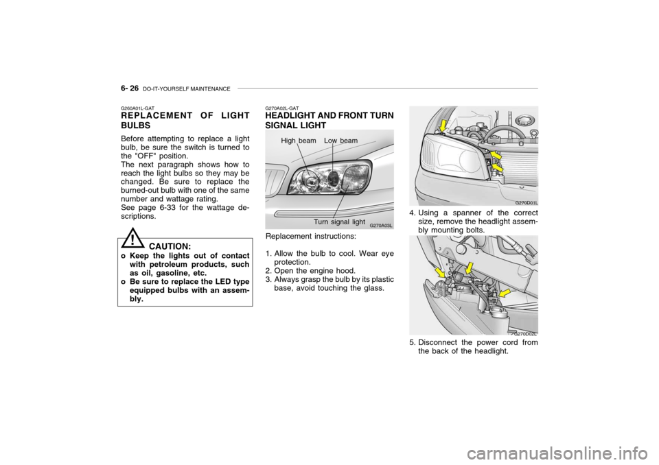
HEADLIGHT AND FRONT TURN SIGNAL LIGHT
High beam Low beam
Turn signal light
G270D01L
4. Using a spanner of the correct size, remove the headlight assem- bly mounting bolts.
G270D02L
5. Disconnect the power cord from the back of the headlight.
Page 209 of 235
DO-IT-YOURSELF MAINTENANCE 6- 27
G270A04L
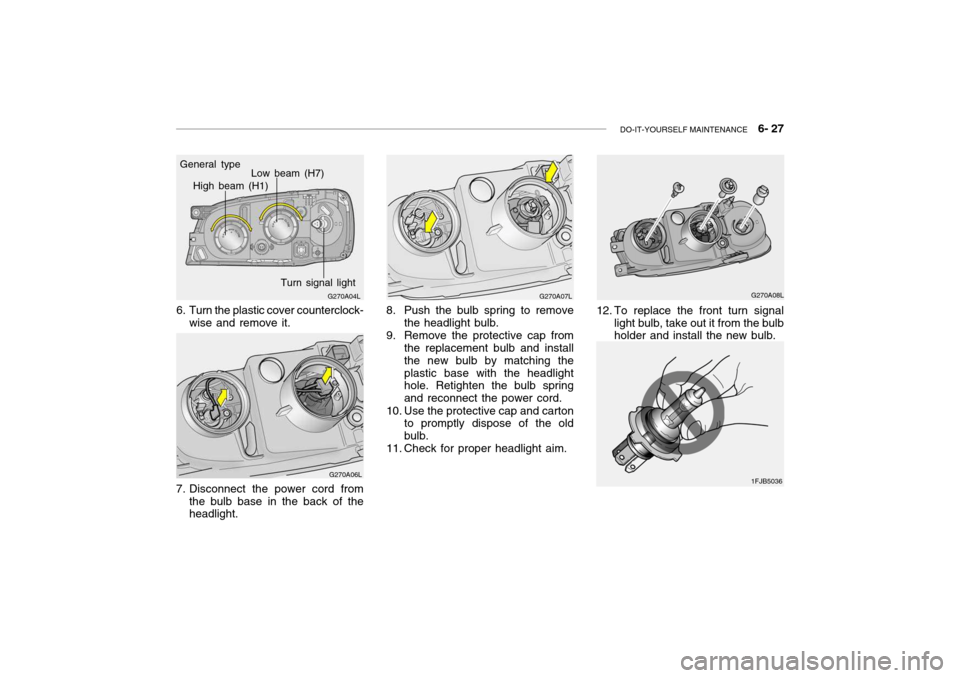
General type
High beam (H1)
Low beam (H7)
Turn signal light
6. Turn the plastic cover counterclock- wise and remove it.
G270A06L
7. Disconnect the power cord from the bulb base in the back of the headlight.
G270A07L
8. Push the bulb spring to remove the headlight bulb.
9. Remove the protective cap from the replacement bulb and install the new bulb by matching theplastic base with the headlight hole. Retighten the bulb spring and reconnect the power cord.
10. Use the protective cap and carton to promptly dispose of the oldbulb.
11. Check for proper headlight aim.
12. To replace the front turn signal light bulb, take out it from the bulb holder and install the new bulb. G270A08L
1FJB5036
Page 210 of 235
6- 28 DO-IT-YOURSELF MAINTENANCE
G270I01L-GAT
FRONT FOG LIGHT
G270D01L
1. Remove the headlight assembly mounting bolts.
G270D02L
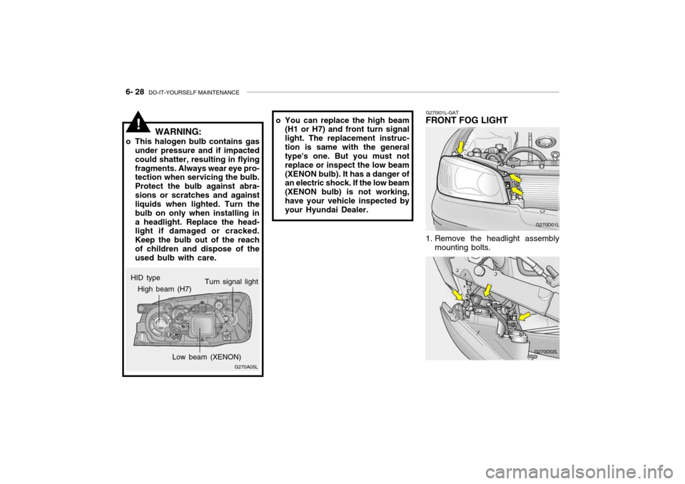
HID type
!
G270A05L
High beam (H7)
Low beam (XENON)Turn signal light
WARNING:
o This halogen bulb contains gas under pressure and if impacted could shatter, resulting in flyingfragments. Always wear eye pro- tection when servicing the bulb. Protect the bulb against abra-sions or scratches and against liquids when lighted. Turn the bulb on only when installing ina headlight. Replace the head- light if damaged or cracked. Keep the bulb out of the reachof children and dispose of the used bulb with care. o You can replace the high beam
(H1 or H7) and front turn signal light. The replacement instruc-tion is same with the general type's one. But you must not replace or inspect the low beam(XENON bulb). It has a danger of an electric shock. If the low beam (XENON bulb) is not working,have your vehicle inspected by your Hyundai Dealer.