OD off Hyundai H-1 (Grand Starex) 2004 Owner's Manual
[x] Cancel search | Manufacturer: HYUNDAI, Model Year: 2004, Model line: H-1 (Grand Starex), Model: Hyundai H-1 (Grand Starex) 2004Pages: 273, PDF Size: 11.26 MB
Page 14 of 273
YOUR VEHICLE AT A GLANCE
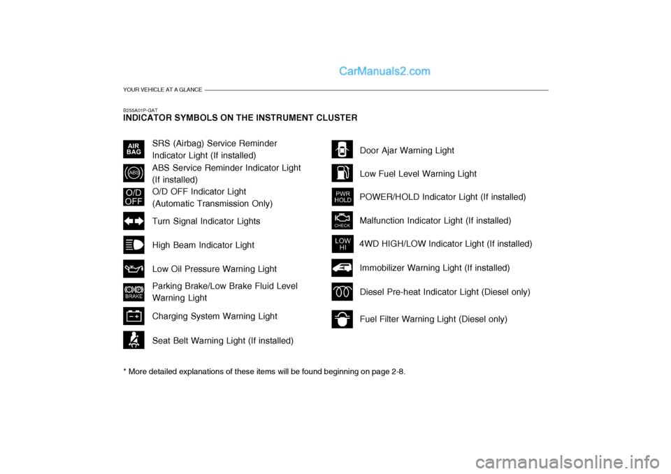
B255A01P-GAT INDICATOR SYMBOLS ON THE INSTRUMENT CLUSTER * More detailed explanations of these items will be found beginning on page 2-8.
O/D OFF Indicator Light (Automatic Transmission Only)
Fuel Filter Warning Light (Diesel only)
Diesel Pre-heat Indicator Light (Diesel only)
Immobilizer Warning Light (If installed)
SRS (Airbag) Service Reminder Indicator Light (If installed)
ABS Service Reminder Indicator Light(If installed)
Turn Signal Indicator Lights High Beam Indicator LightLow Oil Pressure Warning Light Parking Brake/Low Brake Fluid Level Warning Light Charging System Warning Light Seat Belt Warning Light (If installed) Door Ajar Warning Light Low Fuel Level Warning Light
POWER/HOLD Indicator Light (If installed) Malfunction Indicator Light (If installed)
4WD HIGH/LOW Indicator Light (If installed)
Page 22 of 273
1BEFORE DRIVING YOUR VEHICLE
8
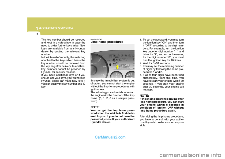
The key number should be recorded and kept in a safe place in case theneed to order further keys arise. New keys are available from any Hyundai dealer by quoting the relevant keynumber. In the interest of security, the metal tag attached to the keys which bears thekey number should be removed from the key ring after delivery. In addition, key numbers cannot be provided byHyundai for security reasons. If you need additional keys or if you should lose your keys, your authorizedHyundai dealer can make new keys if you can supply the key number and ID key. B880D02E-GAT Limp home procedures
1. To set the password, you may turn
the ignition key "ON" and then turn it "OFF" according to the digit num- bers. For example, turn the ignition key once for digit number "1", andtwice for "2", and so on. However, for the digit number "0", you must turn the ignition key for 10 times.
2. Wait for 3~10 seconds.
3. You may set the remaining number
of digits by following the same pro- cedures 1 and 2.
4. If all of four digits have been tried
successfully, from this time, youhave to start your engine within 30 seconds. If you start your engine after 30 seconds, your engine willnot start.
NOTE: If the engine dies while driving after limp home procedure, you can startyour engine within 8 seconds in condition of ignition OFF without limp home procedure again. After doing the limp home procedure, you have to consult with your autho-rized Hyundai dealer as soon as pos- sible.
B880D02P
In case the immobilizer system is out of order, you cannot start the enginewithout the limp home procedures with ignition key. The following procedure is how to startthe engine with the function of the limp home. (0, 1, 2, 3 as a sample pass- word). NOTE: You can get the limp home pass- word when the vehicle is first deliv- ered to you. If you do not have thepassword, consult your authorized Hyundai dealer.
Page 25 of 273
1
BEFORE DRIVING YOUR VEHICLE
11ILLUMINATED IGNITION SWITCH
NOTE: You can get the limp home pass- word when the vehicle is first deliv- ered to you. If you do not have thepassword, consult your authorized Hyundai dealer.
1. To set the password you may turn the ignition key "ON" and then turn it "OFF" according to the digit num-bers, then the immobilizer indicator will blink along with the operation of the ignition key. For example, turnthe ignition key once for digit num- ber "1", and twice for "2", and so on. However, for the digit number "0",you must turn the ignition key for 10 times.
2. Wait for 3~10 seconds.
3. You may set the remaining number of digits by following the same pro-cedures 1 and 2.
4. If all of four digits have been tried successfully, turn the ignition key"ON" and check that the immobi-lizer indicator illuminates. From this time, you have to start your engine within 30 seconds. If you start yourengine after 30 seconds, your en- gine will not start. NOTE: If the engine dies while driving after limp home procedure, you can start your engine within 8 seconds with-out limp home procedure again.
5. If the immobilizer indicator blinks for
five seconds, you have to try the limp home procedure again from the beginning.
After doing the limp home procedure,you have to consult with your autho-rized Hyundai dealer as soon as pos- sible.
CAUTION:
o If you fail to try the limp home procedure with the sequence of three times, you have to wait for about one hour to do the limp home procedure again.
o If you cannot start your engine in spite of limp home procedure,have your vehicle towed by anauthorized Hyundai dealer.
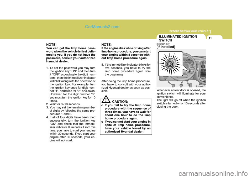
! B120A02P-GAT (If installed) Whenever a front door is opened, the ignition switch will illuminate for yourconvenience. The light will go off when the ignition switch is turned on or 10 seconds afterclosing the door.
B120A02P
Page 29 of 273
1
BEFORE DRIVING YOUR VEHICLE
15
B160B01P-GAT CARRYING CHILDREN
o If a child is left in the vehicle alone,
always be sure to turn off the igni- tion and remove the key.
o If a child is seated alone in the
second seat, use the child-protec-tion system.
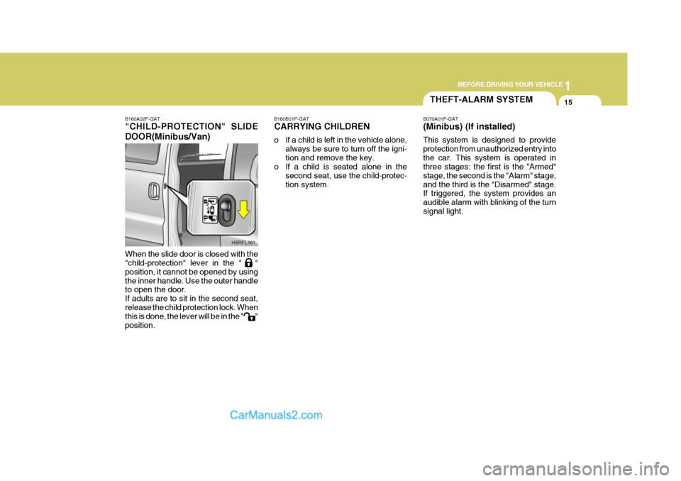
B160A02P-GAT "CHILD-PROTECTION" SLIDE DOOR(Minibus/Van) When the slide door is closed with the "child-protection" lever in the " " position, it cannot be opened by usingthe inner handle. Use the outer handle to open the door. If adults are to sit in the second seat,release the child protection lock. When this is done, the lever will be in the " " position.
HSRFL161
THEFT-ALARM SYSTEM
B070A01P-GAT (Minibus) (If installed) This system is designed to provide protection from unauthorized entry intothe car. This system is operated in three stages: the first is the "Armed" stage, the second is the "Alarm" stage,and the third is the "Disarmed" stage. If triggered, the system provides an audible alarm with blinking of the turnsignal light.
Page 31 of 273
1
BEFORE DRIVING YOUR VEHICLE
17
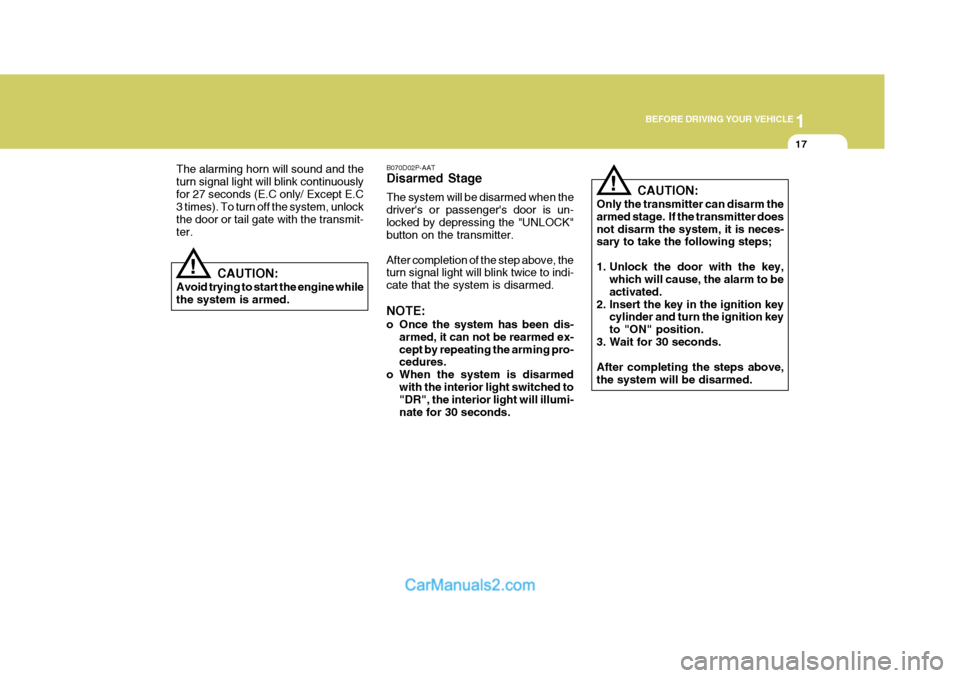
B070D02P-AAT Disarmed Stage The system will be disarmed when the driver's or passenger's door is un-locked by depressing the "UNLOCK" button on the transmitter. After completion of the step above, the turn signal light will blink twice to indi- cate that the system is disarmed. NOTE:
o Once the system has been dis- armed, it can not be rearmed ex- cept by repeating the arming pro- cedures.
o When the system is disarmed
with the interior light switched to"DR", the interior light will illumi- nate for 30 seconds.
The alarming horn will sound and theturn signal light will blink continuouslyfor 27 seconds (E.C only/ Except E.C 3 times). To turn off the system, unlock the door or tail gate with the transmit-ter.
CAUTION:
Avoid trying to start the engine whilethe system is armed.
! CAUTION:
Only the transmitter can disarm the armed stage. If the transmitter doesnot disarm the system, it is neces- sary to take the following steps;
1. Unlock the door with the key, which will cause, the alarm to be activated.
2. Insert the key in the ignition key cylinder and turn the ignition keyto "ON" position.
3. Wait for 30 seconds. After completing the steps above, the system will be disarmed.
!
Page 43 of 273
1
BEFORE DRIVING YOUR VEHICLE
29
!
!
B080A01A-AAT ADJUSTABLE FRONT SEATS
WARNING:
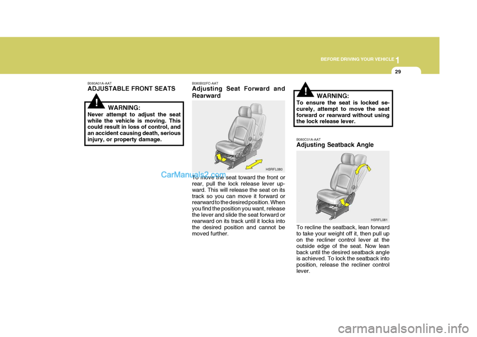
Never attempt to adjust the seat while the vehicle is moving. This could result in loss of control, and an accident causing death, seriousinjury, or property damage. B080B02FC-AAT Adjusting Seat Forward and Rearward To move the seat toward the front or rear, pull the lock release lever up- ward. This will release the seat on itstrack so you can move it forward or rearward to the desired position. When you find the position you want, releasethe lever and slide the seat forward or rearward on its track until it locks into the desired position and cannot bemoved further.B080C01A-AAT Adjusting Seatback Angle To recline the seatback, lean forward to take your weight off it, then pull up on the recliner control lever at the outside edge of the seat. Now leanback until the desired seatback angle is achieved. To lock the seatback into position, release the recliner controllever.
HSRFL080
HSRFL081
WARNING:
To ensure the seat is locked se-curely, attempt to move the seatforward or rearward without using the lock release lever.
Page 50 of 273
1BEFORE DRIVING YOUR VEHICLE
36
!
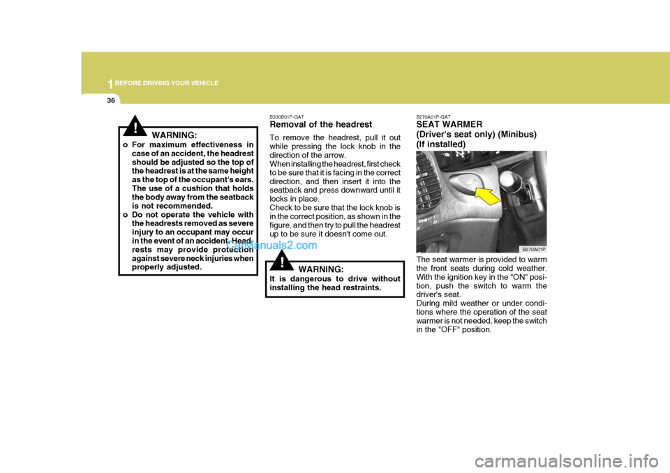
B270A01P-GAT SEAT WARMER (Driver's seat only) (Minibus)(If installed) The seat warmer is provided to warm the front seats during cold weather. With the ignition key in the "ON" posi-tion, push the switch to warm the driver's seat. During mild weather or under condi-tions where the operation of the seat warmer is not needed, keep the switch in the "OFF" position.
!
B330B01P-GAT Removal of the headrest To remove the headrest, pull it out while pressing the lock knob in thedirection of the arrow. When installing the headrest, first check to be sure that it is facing in the correctdirection, and then insert it into the seatback and press downward until it locks in place.Check to be sure that the lock knob is in the correct position, as shown in the figure, and then try to pull the headrestup to be sure it doesn't come out.
WARNING:
It is dangerous to drive without installing the head restraints.
WARNING:
o For maximum effectiveness in case of an accident, the headrest should be adjusted so the top of the headrest is at the same height as the top of the occupant's ears.The use of a cushion that holds the body away from the seatback is not recommended.
o Do not operate the vehicle with the headrests removed as severeinjury to an occupant may occur in the event of an accident. Head- rests may provide protectionagainst severe neck injuries when properly adjusted.
B270A01P
Page 59 of 273
1
BEFORE DRIVING YOUR VEHICLE
45
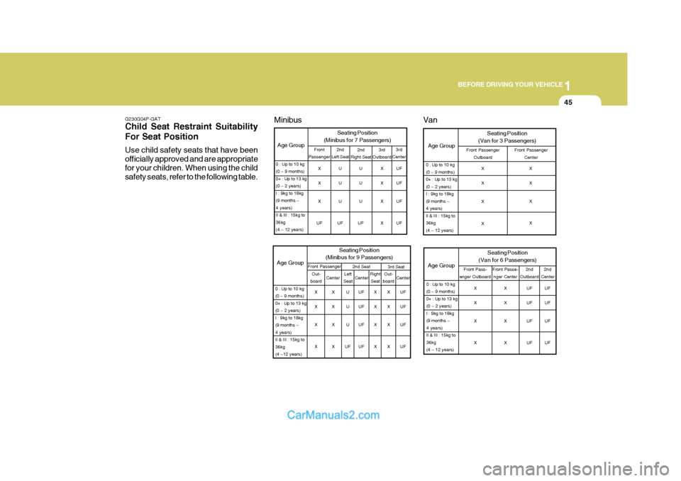
G230G04P-GAT Child Seat Restraint Suitability For Seat Position Use child safety seats that have been officially approved and are appropriatefor your children. When using the child safety seats, refer to the following table. UF UF UF UF
0 : Up to 10 kg (0 ~ 9 months)0+ : Up to 13 kg(0 ~ 2 years)I : 9kg to 18kg(9 months ~4 years)II & III : 15kg to36kg(4 ~ 12 years) 3rd
Center
3rd
Outboard
Age Group Seating Position
(Minibus for 7 Passengers)2nd
Left Seat2nd
Right Seat
U U U
UF U U U
UF X X X X
Front
Passenger
X X X
UF
3rd SeatAge Group Seating Position
(Minibus for 9 Passengers)Front Passenger 2nd Seat
0 : Up to 10 kg (0 ~ 9 months)0+ : Up to 13 kg(0 ~ 2 years)I : 9kg to 18kg(9 months ~4 years)II & III : 15kg to36kg(4 ~12 years)Out-
board Center Left
Seat Right
Seat
Center Out-
board Center
X X X X X X X XU U U
UF UF UF UF UF X X X XX X X XUF UF UF UF
Age Group
Seating Position
(Van for 3 Passengers)Front Passenger Outboard Front Passenger
Center
0 : Up to 10 kg (0 ~ 9 months)0+ : Up to 13 kg(0 ~ 2 years)I : 9kg to 18kg(9 months ~4 years)II & III : 15kg to36kg(4 ~ 12 years)
X X X X X X X X
Age Group
0 : Up to 10 kg (0 ~ 9 months)0+ : Up to 13 kg(0 ~ 2 years)I : 9kg to 18kg(9 months ~4 years)II & III : 15kg to36kg(4 ~ 12 years)
Van
2nd
Center
2nd
Outboard
Seating Position
(Van for 6 Passengers)
Front Pass-
enger Outboard Front Passe-
nger Center
X X X X X X X XUF UF UF UFUF UF UF UF
Minibus
Page 61 of 273
1
BEFORE DRIVING YOUR VEHICLE
47
!
the front passenger with additional pro- tection than that offered by the seat-belt system alone, in case of a frontal impact of sufficient severity.) NOTE: Be sure to read information about the SRS on the labels provided on the backside of the sun visor and in the glove box.
WARNING:
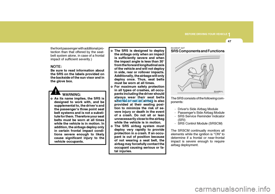
o As its name implies, the SRS is designed to work with, and besupplemental to, the driver's andthe passenger's three point seat belt systems and is not a substi- tute for them. Therefore your seatbelts must be worn at all times while the vehicle is in motion. In addition, the airbags deploy onlyin certain frontal impact condi- tions severe enough to likely cause significant injury to thevehicle occupants.B240B02P-AAT SRS Components and Functions The SRS consists of the following com- ponents:
- Driver's Side Airbag Module
- Passenger's Side Airbag Module
- SRS Service Reminder Indicator(SRI)
- SRS Control Module (SRSCM)
The SRSCM continually monitors allelements while the ignition is "ON" todetermine if a frontal or near-frontal impact is severe enough to require airbag deployment. B240B01Lo The SRS is designed to deploy
the airbags only when an impact is sufficiently severe and when the impact angle is less than 30° from the forward longitudinal axisof the vehicle and will not deploy in side, rear or rollover impacts. Additionally, the airbags will onlydeploy once. Thus, seat belts must be worn at all times.
o For maximum safety protection
in all types of crashes, all occu-pants including the driver should always wear their seat beltswhether or not an airbag is also provided at their seating posi- tion to minimize the risk of se-vere injury or death in the event of a crash. Do not sit or lean unnecessarily close to the airbagwhile the vehicle is in motion.
o The SRS airbag system must
deploy very rapidly to provideprotection in a crash. If an occu- pant is out of position because of not wearing a seat belt, theairbag may forcefully contact the occupant causing serious or fa- tal injuries.
Page 68 of 273
2
INSTRUMENTS AND CONTROLS
3
1. Malfunction indicator light (MIL) (If installed)
2. Oil pressure warning light
3. Brake warning and parking brake indicator light
4. Seat belt warning light (If installed)
5. Immobilizer warning light (If installed)
6. Turn-signal indicator lights
7. Automatic transmission position indicator light (Automatic transmission only)
8. POWER/HOLD mode indicator light
(Automatic transmission only)
9. High-beam indicator light
10. ABS Service reminder indicator light (SRI) (If installed)
11. SRS (Airbag) service reminder indicator light (If installed) 12. Overdrive off indicator light
(Automatic transmission only)
13. Diesel preheat indicator light (Diesel only)
14. Tachometer (If installed)
15. Low fuel level warning light
16. Fuel filter warning light (Diesel only)
17. Charging system warning light
18. Coolant Temperature gauge
19. Odometer/Trip odometer
20. Fuel gauge
21. 4WD LOW/Hl indicator light
22. Trip odometer reset switch
23. Speedmeter
24. Door-ajar warning light