instrument panel Hyundai H-1 (Grand Starex) 2004 Owner's Manual
[x] Cancel search | Manufacturer: HYUNDAI, Model Year: 2004, Model line: H-1 (Grand Starex), Model: Hyundai H-1 (Grand Starex) 2004Pages: 273, PDF Size: 11.26 MB
Page 11 of 273
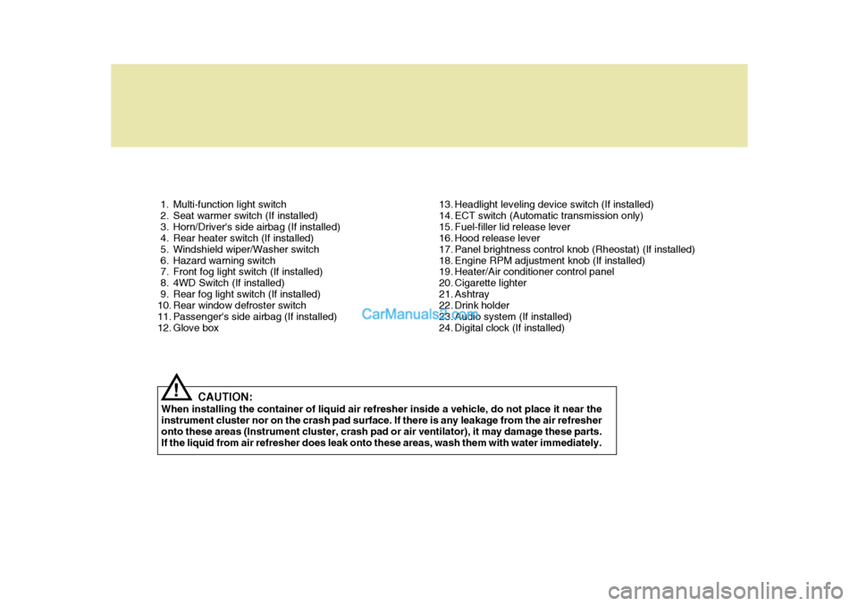
1. Multi-function light switch
2. Seat warmer switch (If installed)
3. Horn/Driver's side airbag (If installed)
4. Rear heater switch (If installed)
5. Windshield wiper/Washer switch
6. Hazard warning switch
7. Front fog light switch (If installed)
8. 4WD Switch (If installed)
9. Rear fog light switch (If installed)
10. Rear window defroster switch
11. Passenger's side airbag (If installed)
12. Glove box13. Headlight leveling device switch (If installed)
14. ECT switch (Automatic transmission only)
15. Fuel-filler lid release lever
16. Hood release lever
17. Panel brightness control knob (Rheostat) (If installed)
18. Engine RPM adjustment knob (If installed)
19. Heater/Air conditioner control panel
20. Cigarette lighter
21. Ashtray
22. Drink holder
23. Audio system (If installed)
24. Digital clock (If installed)
CAUTION:
When installing the container of liquid air refresher inside a vehicle, do not place it near theinstrument cluster nor on the crash pad surface. If there is any leakage from the air refresher onto these areas (Instrument cluster, crash pad or air ventilator), it may damage these parts. If the liquid from air refresher does leak onto these areas, wash them with water immediately.
!
Page 13 of 273
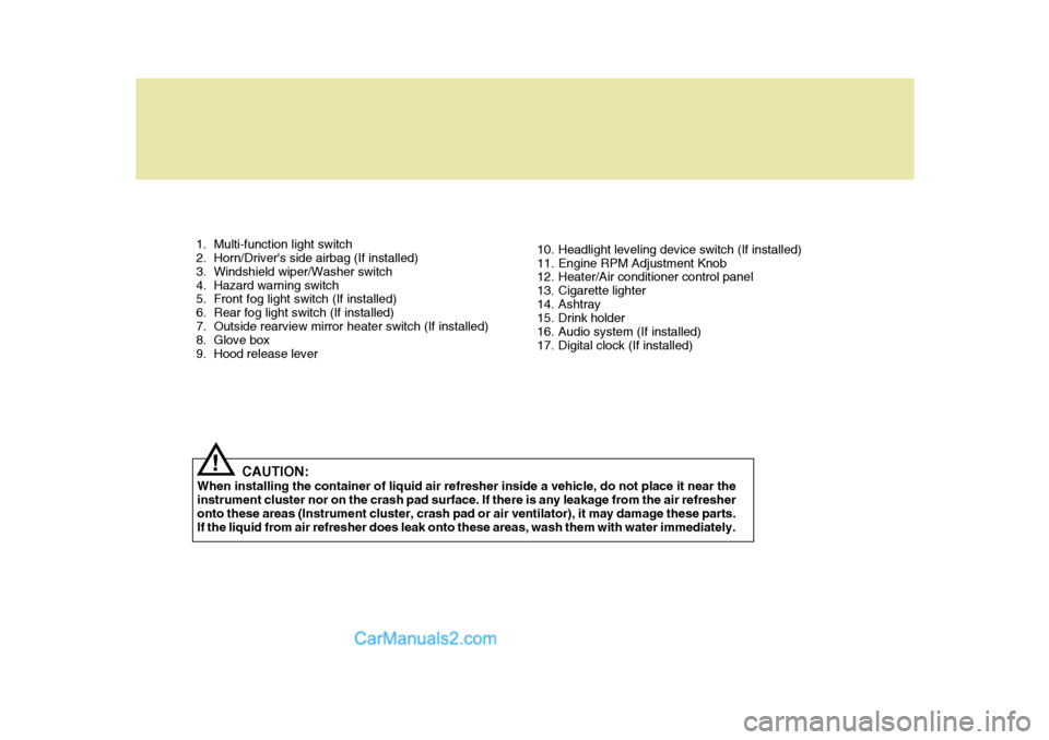
1. Multi-function light switch
2. Horn/Driver's side airbag (If installed)
3. Windshield wiper/Washer switch
4. Hazard warning switch
5. Front fog light switch (If installed)
6. Rear fog light switch (If installed)
7. Outside rearview mirror heater switch (If installed)
8. Glove box
9. Hood release lever10. Headlight leveling device switch (If installed)
11. Engine RPM Adjustment Knob
12. Heater/Air conditioner control panel
13. Cigarette lighter
14. Ashtray
15. Drink holder
16. Audio system (If installed)
17. Digital clock (If installed)
CAUTION:
When installing the container of liquid air refresher inside a vehicle, do not place it near theinstrument cluster nor on the crash pad surface. If there is any leakage from the air refresheronto these areas (Instrument cluster, crash pad or air ventilator), it may damage these parts. If the liquid from air refresher does leak onto these areas, wash them with water immediately.
!
Page 62 of 273
1BEFORE DRIVING YOUR VEHICLE
48
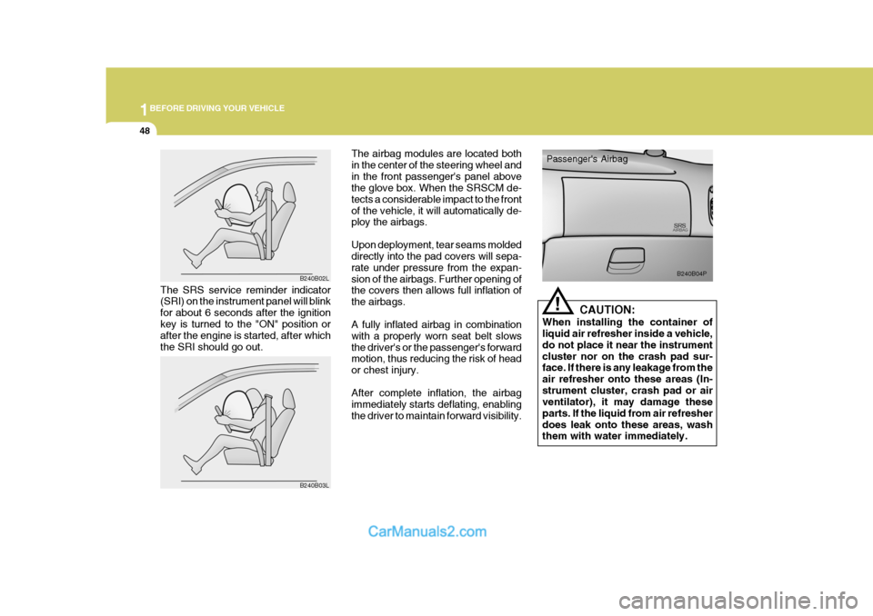
The airbag modules are located both in the center of the steering wheel andin the front passenger's panel above the glove box. When the SRSCM de- tects a considerable impact to the frontof the vehicle, it will automatically de- ploy the airbags. Upon deployment, tear seams molded directly into the pad covers will sepa- rate under pressure from the expan-sion of the airbags. Further opening of the covers then allows full inflation of the airbags. A fully inflated airbag in combination with a properly worn seat belt slowsthe driver's or the passenger's forward motion, thus reducing the risk of head or chest injury. After complete inflation, the airbag immediately starts deflating, enablingthe driver to maintain forward visibility. CAUTION:
When installing the container of liquid air refresher inside a vehicle, do not place it near the instrumentcluster nor on the crash pad sur- face. If there is any leakage from the air refresher onto these areas (In-strument cluster, crash pad or air ventilator), it may damage these parts. If the liquid from air refresherdoes leak onto these areas, wash them with water immediately.
!
Passenger's Airbag
B240B04P
The SRS service reminder indicator (SRI) on the instrument panel will blink for about 6 seconds after the ignitionkey is turned to the "ON" position or after the engine is started, after which the SRI should go out. B240B02L
B240B03L
Page 64 of 273
1BEFORE DRIVING YOUR VEHICLE
50
o For cleaning the airbag pad cov-
ers, use only a soft, dry cloth or one which has been moistened with plain water. Solvents orcleaners could adversely affect the airbag covers and proper deployment of the system.
o No objects should be placed over or near the airbag modules onthe steering wheel, instrumentpanel, and the front passenger's panel above the glove box, be- cause any such object couldcause harm if the vehicle is in a crash severe enough to cause the airbags to inflate.
o If the airbags inflate, they must be replaced by an authorizedHyundai dealer.
o Do not tamper with or discon- nect SRS wiring, or other com-ponents of the SRS system. Do-ing so could result in injury, due to accidental firing of the airbags or by rendering the SRS inopera-tive.o Do not install a child restraint
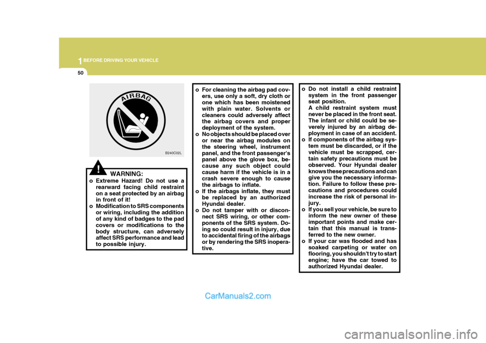
system in the front passenger seat position. A child restraint system mustnever be placed in the front seat. The infant or child could be se- verely injured by an airbag de-ployment in case of an accident.
o If components of the airbag sys-
tem must be discarded, or if thevehicle must be scrapped, cer- tain safety precautions must be observed. Your Hyundai dealerknows these precautions and can give you the necessary informa- tion. Failure to follow these pre-cautions and procedures could increase the risk of personal in- jury.
o If you sell your vehicle, be sure to inform the new owner of theseimportant points and make cer-tain that this manual is trans- ferred to the new owner.
o If your car was flooded and has soaked carpeting or water onflooring, you shouldn't try to start engine; have the car towed toauthorized Hyundai dealer.
!WARNING:
o Extreme Hazard! Do not use a rearward facing child restraint on a seat protected by an airbag in front of it!
o Modification to SRS components
or wiring, including the additionof any kind of badges to the pad covers or modifications to thebody structure, can adversely affect SRS performance and lead to possible injury. B240C02L
Page 66 of 273
2
Instrument Cluster And Indicator Lights ....................... 2-2
Warning And Indicator Lights ....................................... 2-8
Instrument Cluster ......................................................2-12
Odometer/Trip odmeter .............................................. 2-14
Multim eter ................................................................... 2-16
Muti-funition Light Switch ........................................... 2-19
Windshield Wiper And Washer Switch .......................2-21
Headlamp Leveling Device System ........................... 2-23
Instrument Panel Light Control (Rheostat) ................ 2-24
Engine Rpm Adjustment Knob ................................... 2-24
Fog Lamp Switch ....................................................... 2-25
Front/Rear Window Defroster Switch ......................... 2-26
Interior Light ............................................................... 2-28
Sunroof ....................................................................... 2-30
Mirror .......................................................................... 2-34
Drink Holder ................................................................ 2-35
Ashtray ....................................................................... 2-36
Digital Clock ................................................................ 2-37
Horn ............................................................................ 2-37
Heating And Cooling Control ..................................... 2-38
Rear Heater And Air Conditioner ............................... 2-45
Overhead Air Conditioning ......................................... 2-47
Air Conditioner Filter ................................................... 2-47
Stereo Sound System ................................................ 2-49
Audio System ............................................................. 2-51
Antenna ...................................................................... 2-73
INSTRUMENTS AND CONTROLS
2
Page 84 of 273
2
INSTRUMENTS AND CONTROLS
19MUTI-FUNITION LIGHT SWITCH
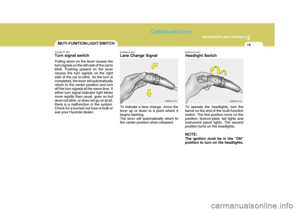
B340C01P-AAT Headlight Switch
To operate the headlights, turn the barrel on the end of the multi-function switch. The first position turns on theposition, licence-plate, tail lights and instrument panel lights. The second position turns on the headlights. NOTE: The ignition must be in the "ON" position to turn on the headlights.
B340B01A-AAT Lane Change Signal To indicate a lane change, move the lever up or down to a point where it begins flashing.The lever will automatically return to the center position when released.
HSRFL2113
HSRFL2114
C150A01P-GAT Turn signal switch Pulling down on the lever causes the turn signals on the left side of the car toblink. Pushing upward on the lever causes the turn signals on the right side of the car to blink. As the turn iscompleted, the lever will automatically return to the center position and turn off the turn signals at the same time. Ifeither turn signal indicator light blinks more rapidly than usual, goes on but does not blink, or does not go on at all,there is a malfunction in the system. Check for a burned-out fuse or bulb or see your Hyundai dealer.
Page 89 of 273
2 INSTRUMENTS AND CONTROLS
24INSTRUMENT PANEL LIGHT CONTROL (RHEOSTAT)
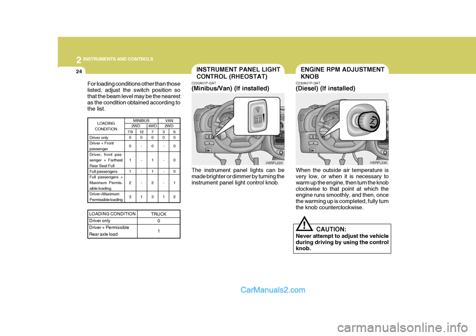
C220A01P-GAT (Minibus/Van) (If installed)
HSRFL220
The instrument panel lights can be made brighter or dimmer by turning the instrument panel light control knob.
For loading conditions other than thoselisted, adjust the switch position sothat the beam level may be the nearest as the condition obtained according to the list.
MINIBUS2WD4WD 2WD
7/9
0 0 1 1 2 3 3 0
- - - -
1 6 0 0 0 0 1 2
7 0 0 1 1 2 3
LOADING
CONDITION
Driver only Driver + Frontpassenger Driver, front pas- senger + FarthestRear Seat Full Full passengers Full passengers +Maximum Permis- sible loading Driver+MaximumPermissible loading12 0
- - - -
1
LOADING CONDITION Driver onlyDriver + PermissibleRear axle load
TRUCK 0 1
VAN
ENGINE RPM ADJUSTMENT KNOB
C230A01P-GAT (Diesel) (If installed)
When the outside air temperature is very low, or when it is necessary to warm up the engine, then turn the knobclockwise to that point at which the engine runs smoothly, and then, once the warming up is completed, fully turnthe knob counterclockwise. CAUTION:
Never attempt to adjust the vehicleduring driving by using the control knob.
! HSRFL230
Page 90 of 273
2
INSTRUMENTS AND CONTROLS
25FRONT FOG LIGHT SWITCH
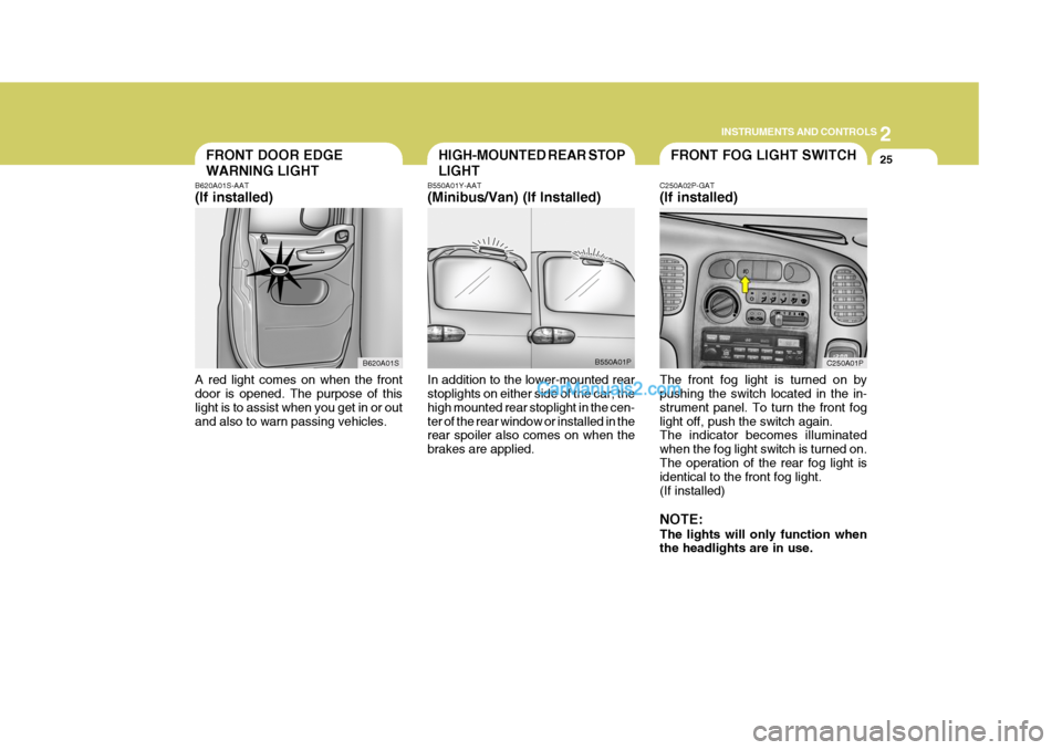
C250A02P-GAT (If installed) The front fog light is turned on by pushing the switch located in the in- strument panel. To turn the front foglight off, push the switch again. The indicator becomes illuminated when the fog light switch is turned on.The operation of the rear fog light is identical to the front fog light. (If installed) NOTE: The lights will only function when the headlights are in use. C250A01PFRONT DOOR EDGE WARNING LIGHT
B620A01S-AAT (If installed) A red light comes on when the front door is opened. The purpose of this light is to assist when you get in or outand also to warn passing vehicles. B620A01SHIGH-MOUNTED REAR STOP LIGHT
B550A01Y-AAT (Minibus/Van) (If Installed) In addition to the lower-mounted rear stoplights on either side of the car, the high mounted rear stoplight in the cen-ter of the rear window or installed in the rear spoiler also comes on when the brakes are applied. B550A01P
Page 95 of 273
2 INSTRUMENTS AND CONTROLS
30
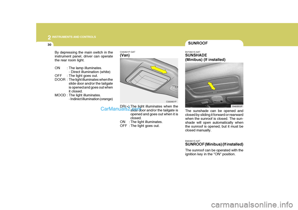
C330A01P-GAT (Van) DR(
·):The light illuminates when the
slide door and/or the tailgate is opened and goes out when it isclosed.
ON : The light illuminates.
OFF : The light goes out.
By depressing the main switch in theinstrument panel, driver can operatethe rear room light.
ON : The lamp illuminates.
- Direct illumination (white)
OFF : The light goes out.
DOOR : The light illuminates when theslide door and/or the tailgate is opened and goes out when it closed.
MOOD : The light illuminates. - Indirect illumination (orange)
C330A01P
SUNROOF
B470A01S-AAT SUNSHADE (Minibus) (If installed) The sunshade can be opened and closed by sliding it forward or rearward when the sunroof is closed. The sun- shade will open automatically whenthe sunroof is opened, but it must be closed manually. B460A01S-AAT SUNROOF (Minibus) (If installed) The sunroof can be operated with the ignition key in the "ON" position. B460B03P
B460B03P
Page 96 of 273
2
INSTRUMENTS AND CONTROLS
31
!
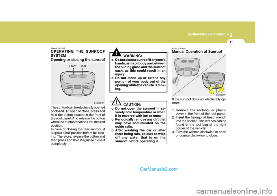
! B460D01P-GAT Manual Operation of Sunroof If the sunroof does not electrically op- erate:
1. Remove the rectangular plastic
cover in the front of the roof panel.
2. Insert the hexagonal head wrench
into the socket. This wrench can be found in the tool bag at the right corner of the vehicle.
3. Turn the wrench clockwise to open or counterclockwise to close.
WARNING:
o Do not close a sunroof if anyone's hands, arms or body are betweenthe sliding glass and the sunroofsash, as this could result in an injury.
o Do not stand up or extend any portion of your body out of theopening while the vehicle is mov- ing.
CAUTION:
o Do not open the sunroof in se- verely cold temperature or when it is covered with ice or snow.
o Periodically remove any dirt that may have accumulated on theguide rails.
o After washing the car or after
there being rain, be sure to wipeoff any water that is on the sunroof before operating it. B460D01P
B460B03P-GAT OPERATING THE SUNROOF SYSTEMOpening or closing the sunroof The sunfoof can be electrically opened or closed. To open or close, press and hold the button located in the front ofthe roof panel. And release the button when the sunfoof reaches the desired position.In case of closing the rear sunroof, it stops at a half position before full clos- ing. Therefore, release the button andthen press and hold it again to close it completely. Front
B460B01P
Rear