light Hyundai H-1 (Grand Starex) 2005 Owner's Manual
[x] Cancel search | Manufacturer: HYUNDAI, Model Year: 2005, Model line: H-1 (Grand Starex), Model: Hyundai H-1 (Grand Starex) 2005Pages: 205, PDF Size: 9.14 MB
Page 11 of 205
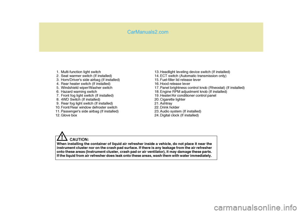
1. Multi-function light switch
2. Seat warmer switch (If installed)
3. Horn/Driver's side airbag (If installed)
4. Rear heater switch (If installed)
5. Windshield wiper/Washer switch
6. Hazard warning switch
7. Front fog light switch (If installed)
8. 4WD Switch (If installed)
9. Rear fog light switch (If installed)
10. Front/Rear window defroster switch
11. Passenger's side airbag (If installed)
12. Glove box13. Headlight leveling device switch (If installed)
14. ECT switch (Automatic transmission only)
15. Fuel-filler lid release lever
16. Hood release lever
17. Panel brightness control knob (Rheostat) (If installed)
18. Engine RPM adjustment knob (If installed)
19. Heater/Air conditioner control panel
20. Cigarette lighter
21. Ashtray
22. Drink holder
23. Audio system (If installed)
24. Digital clock (If installed)
CAUTION:
When installing the container of liquid air refresher inside a vehicle, do not place it near theinstrument cluster nor on the crash pad surface. If there is any leakage from the air refresher onto these areas (Instrument cluster, crash pad or air ventilator), it may damage these parts. If the liquid from air refresher does leak onto these areas, wash them with water immediately.
!
Page 13 of 205
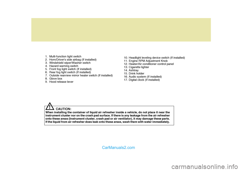
1. Multi-function light switch
2. Horn/Driver's side airbag (If installed)
3. Windshield wiper/Washer switch
4. Hazard warning switch
5. Front fog light switch (If installed)
6. Rear fog light switch (If installed)
7. Outside rearview mirror heater switch (If installed)
8. Glove box
9. Hood release lever10. Headlight leveling device switch (If installed)
11. Engine RPM Adjustment Knob
12. Heater/Air conditioner control panel
13. Cigarette lighter
14. Ashtray
15. Drink holder
16. Audio system (If installed)
17. Digital clock (If installed)
CAUTION:
When installing the container of liquid air refresher inside a vehicle, do not place it near theinstrument cluster nor on the crash pad surface. If there is any leakage from the air refresheronto these areas (Instrument cluster, crash pad or air ventilator), it may damage these parts. If the liquid from air refresher does leak onto these areas, wash them with water immediately.
!
Page 14 of 205
YOUR VEHICLE AT A GLANCE
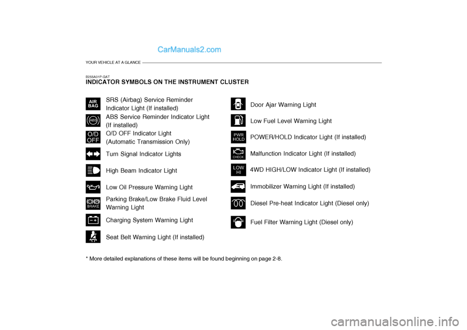
B255A01P-GAT INDICATOR SYMBOLS ON THE INSTRUMENT CLUSTER * More detailed explanations of these items will be found beginning on page 2-8.
O/D OFF Indicator Light (Automatic Transmission Only)
Fuel Filter Warning Light (Diesel only)
Diesel Pre-heat Indicator Light (Diesel only)
Immobilizer Warning Light (If installed)
SRS (Airbag) Service Reminder Indicator Light (If installed)
ABS Service Reminder Indicator Light(If installed)
Turn Signal Indicator Lights High Beam Indicator LightLow Oil Pressure Warning Light Parking Brake/Low Brake Fluid Level Warning Light Charging System Warning Light Seat Belt Warning Light (If installed) Door Ajar Warning Light Low Fuel Level Warning Light
POWER/HOLD Indicator Light (If installed) Malfunction Indicator Light (If installed)
4WD HIGH/LOW Indicator Light (If installed)
Page 16 of 205
1BEFORE DRIVING YOUR VEHICLE
2RUNNING-IN RECOMMEN- DATIONSBEFORE DRIVING YOUR VEHICLE SAFETY CHECKS
Drive range1st
2nd 3rd
4th 5th
!
B010A01P-GAT Be sure you know your vehicle and its equipment and how to use it safely. B010B01P-GAT Before entering the vehicle
o Check that windows, mirrors and lights are clean.
o Check if any tire is low or flat.
o Look for fluid leaks.
o Check that area is clear if you're about to back up.
B010C03P-GAT After entering the vehicle
o Lock all doors.
o The driver and passengers are wear- ing properly adjusted seat belts.
o The head restraints are properly adjusted, if so equipped.
o Adjust inside and outside mirrors.
o Check warning lights for correct
operation, with the ignition key in the position "ON".
o Check all gauges, for normal opera- tion. WARNING: (Diesel only)
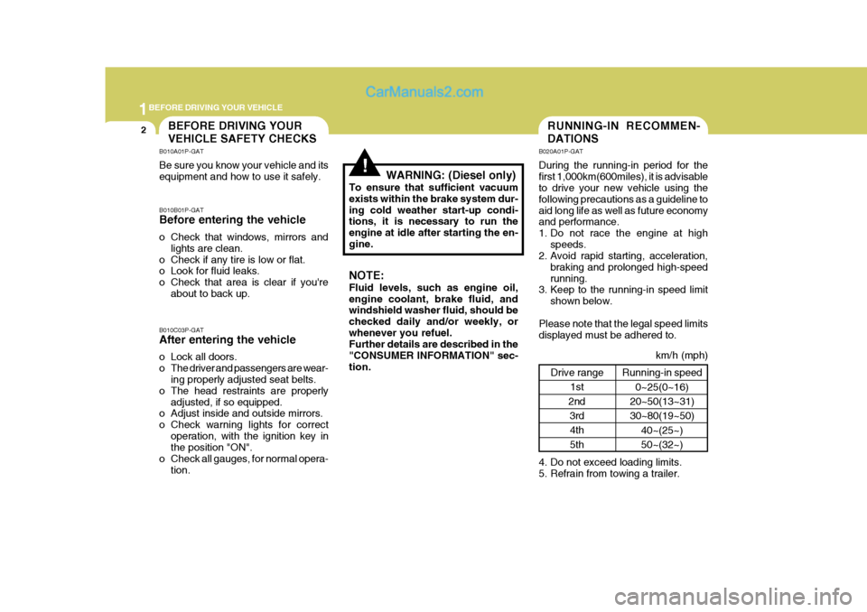
To ensure that sufficient vacuum exists within the brake system dur-ing cold weather start-up condi- tions, it is necessary to run the engine at idle after starting the en-gine. NOTE: Fluid levels, such as engine oil, engine coolant, brake fluid, and windshield washer fluid, should be checked daily and/or weekly, orwhenever you refuel. Further details are described in the "CONSUMER INFORMATION" sec-tion. B020A01P-GAT During the running-in period for the first 1,000km(600miles), it is advisable to drive your new vehicle using the following precautions as a guideline toaid long life as well as future economy and performance.
1. Do not race the engine at high
speeds.
2. Avoid rapid starting, acceleration,
braking and prolonged high-speedrunning.
3. Keep to the running-in speed limit
shown below.
Please note that the legal speed limitsdisplayed must be adhered to.
4. Do not exceed loading limits.
5. Refrain from towing a trailer.
km/h (mph)
Running-in speed 0~25(0~16)
20~50(13~31) 30~80(19~50)
40~(25~) 50~(32~)
Page 20 of 205
1BEFORE DRIVING YOUR VEHICLE
6
B880B01HP-1
IMMOBILIZER SYSTEMKEYS
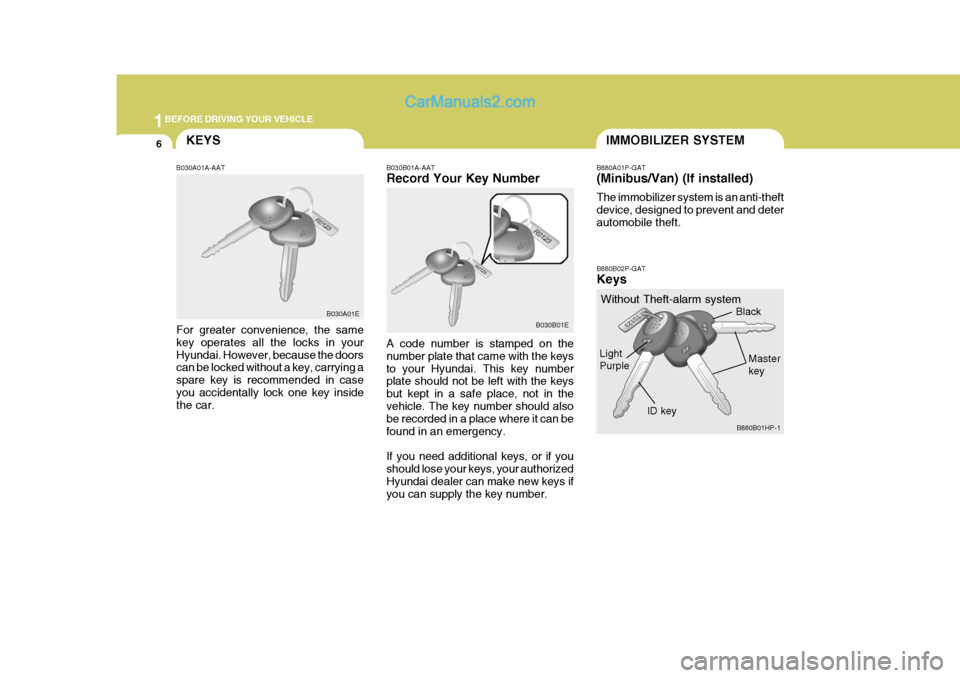
B030A01A-AAT For greater convenience, the same key operates all the locks in yourHyundai. However, because the doors can be locked without a key, carrying a spare key is recommended in caseyou accidentally lock one key inside the car. B030B01A-AAT Record Your Key Number A code number is stamped on the number plate that came with the keysto your Hyundai. This key number plate should not be left with the keys but kept in a safe place, not in thevehicle. The key number should also be recorded in a place where it can be found in an emergency. If you need additional keys, or if you should lose your keys, your authorizedHyundai dealer can make new keys if you can supply the key number.
B030A01E
B030B01EB880A01P-GAT (Minibus/Van) (If installed) The immobilizer system is an anti-theft device, designed to prevent and deterautomobile theft. B880B02P-GAT Keys
Without Theft-alarm system
LightPurple
Black Master key
ID key
Page 25 of 205
1
BEFORE DRIVING YOUR VEHICLE
11ILLUMINATED IGNITION SWITCH
NOTE: You can get the limp home pass- word when the vehicle is first deliv- ered to you. If you do not have thepassword, consult your authorized Hyundai dealer.
1. To set the password you may turn the ignition key "ON" and then turn it "OFF" according to the digit num-bers, then the immobilizer indicator will blink along with the operation of the ignition key. For example, turnthe ignition key once for digit num- ber "1", and twice for "2", and so on. However, for the digit number "0",you must turn the ignition key for 10 times.
2. Wait for 3~10 seconds.
3. You may set the remaining number of digits by following the same pro-cedures 1 and 2.
4. If all of four digits have been tried successfully, turn the ignition key"ON" and check that the immobi-lizer indicator illuminates. From this time, you have to start your engine within 30 seconds. If you start yourengine after 30 seconds, your en- gine will not start. NOTE: If the engine dies while driving after limp home procedure, you can start your engine within 8 seconds with-out limp home procedure again.
5. If the immobilizer indicator blinks for
five seconds, you have to try the limp home procedure again from the beginning.
After doing the limp home procedure,you have to consult with your autho-rized Hyundai dealer as soon as pos- sible.
CAUTION:
o If you fail to try the limp home procedure with the sequence of three times, you have to wait for about one hour to do the limp home procedure again.
o If you cannot start your engine in spite of limp home procedure,have your vehicle towed by anauthorized Hyundai dealer.
! B120A02P-GAT (If installed) Whenever a front door is opened, the ignition switch will illuminate for yourconvenience. The light will go off when the ignition switch is turned on or 10 seconds afterclosing the door.
B120A02P
Page 29 of 205
1
BEFORE DRIVING YOUR VEHICLE
15
B160B01P-GAT CARRYING CHILDREN
o If a child is left in the vehicle alone,
always be sure to turn off the igni- tion and remove the key.
o If a child is seated alone in the
second seat, use the child-protec-tion system.
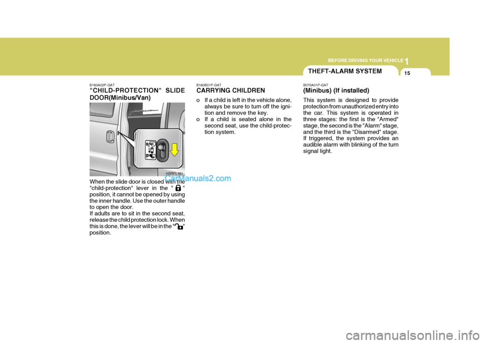
B160A02P-GAT "CHILD-PROTECTION" SLIDE DOOR(Minibus/Van) When the slide door is closed with the "child-protection" lever in the " " position, it cannot be opened by usingthe inner handle. Use the outer handle to open the door. If adults are to sit in the second seat,release the child protection lock. When this is done, the lever will be in the " " position.
HSRFL161
THEFT-ALARM SYSTEM
B070A01P-GAT (Minibus) (If installed) This system is designed to provide protection from unauthorized entry intothe car. This system is operated in three stages: the first is the "Armed" stage, the second is the "Alarm" stage,and the third is the "Disarmed" stage. If triggered, the system provides an audible alarm with blinking of the turnsignal light.
Page 30 of 205
1BEFORE DRIVING YOUR VEHICLE
16
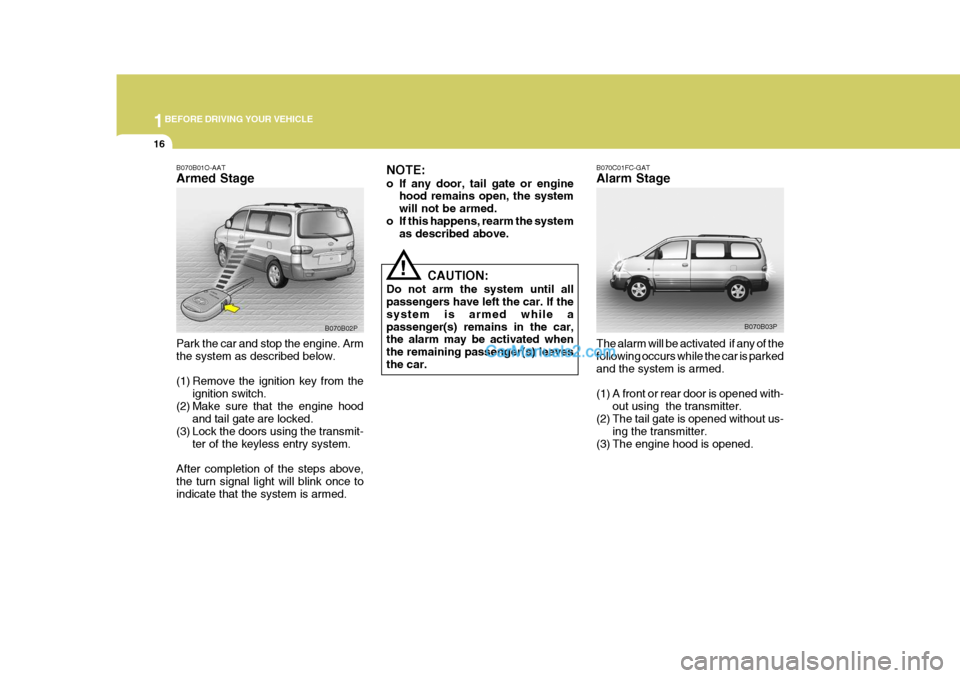
B070C01FC-GAT Alarm Stage The alarm will be activated if any of the following occurs while the car is parkedand the system is armed.
(1) A front or rear door is opened with-
out using the transmitter.
(2) The tail gate is opened without us-
ing the transmitter.
(3) The engine hood is opened. B070B03P
NOTE:
o If any door, tail gate or engine
hood remains open, the system will not be armed.
o If this happens, rearm the system as described above.
CAUTION:
Do not arm the system until all passengers have left the car. If the system is armed while apassenger(s) remains in the car, the alarm may be activated when the remaining passenger(s) leaves the car.
!
B070B01O-AAT Armed Stage Park the car and stop the engine. Arm the system as described below.
(1) Remove the ignition key from the
ignition switch.
(2) Make sure that the engine hood and tail gate are locked.
(3) Lock the doors using the transmit-
ter of the keyless entry system.
After completion of the steps above, the turn signal light will blink once to indicate that the system is armed. B070B02P
Page 31 of 205
1
BEFORE DRIVING YOUR VEHICLE
17
B070D03P-AAT Disarmed Stage The system will be disarmed when the driver's or passenger's door is un-locked by depressing the button on the transmitter after the system was armed. After completion of the step above, the turn signal lights will blink twice to indicate that the system is disarmed. NOTE:
o Once the system has been dis- armed, it can not be rearmed ex- cept by repeating the arming pro- cedures.
o When the system is disarmed
with the interior light switched to"DR", the interior light will illumi- nate for 30 seconds.
The alarming horn will sound and theturn signal light will blink continuouslyfor 27 seconds (E.C only/ Except E.C 3 times). To turn off the system, unlock the door or tail gate with the transmit-ter.
CAUTION:
Avoid trying to start the engine whilethe system is armed.
! CAUTION:
Only the transmitter can disarm the armed stage. If the transmitter doesnot disarm the system, it is neces- sary to take the following steps;
1. Unlock the door with the key, which will cause, the alarm to be activated.
2. Insert the key in the ignition key cylinder and turn the ignition keyto "ON" position.
3. Wait for 30 seconds. After completing the steps above, the system will be disarmed.
!
Page 32 of 205
1BEFORE DRIVING YOUR VEHICLE
18
B070F02A-GAT Keyless Entry System (If installed) Locking doors
1. Close all doors.
2. Push the button on the transmitter.
3. At the same time all doors lock, the
turn signal lights will blink once toindicate that the system is armed.
Unlocking doors 1. Push the button on the transmitter once more after all doors were locked.
2. At the same time all doors unlock,
the turn signal lights will blink twiceto indicate that the system is dis- armed. 3. Remove four screws at the back
side of the built-in circuit. HTB054
HTB055
B070E02P-AAT Replacing the battery When the transmitter's battery be- comes weak, it may take several pushes on the button to lock or unlockthe doors, and the LED will not light. Replace the battery as soon as pos- sible. Battery type : CR1220 (Minibus/Van)
CR2032 (Truck)
Replacement instructions: (Minibus/Van)
1. Remove the screw with a phillips screwdriver.
2. Carefully separate the case with a flat-head screwdriver as shown in the illustration. HTB053
4. Remove the old battery from thecase and note the polarity. Makesure the polarity of the new battery is the same (+side facing up), theninsert it in the transmitter.