glove box Hyundai H-1 (Grand Starex) 2007 Owner's Manual
[x] Cancel search | Manufacturer: HYUNDAI, Model Year: 2007, Model line: H-1 (Grand Starex), Model: Hyundai H-1 (Grand Starex) 2007Pages: 284, PDF Size: 11.33 MB
Page 9 of 284

F9
1. Multi-function light switch
2. Seat warmer switch (If installed)
3. Horn/Driver's side airbag (If installed)
4. Rear heater switch (If installed)
5. Windshield wiper/Washer switch
6. Hazard warning switch
7. Front fog light switch (If installed)
8. 4WD Switch (If installed)
9. Rear fog light switch (If installed)
10. Front/Rear window defroster switch
11. Passenger's side airbag (If installed)
12. Glove box
13. Headlight leveling device switch (If installed)
14. ECT switch (Automatic transmission only)
15. Fuel-filler lid release lever
16. Hood release lever
17. Panel brightness control knob (Rheostat) (If installed)
18. Engine RPM adjustment knob (If installed)
19. Heater/Air conditioner control panel
20. Cigarette lighter
21. Ashtray
22. Drink holder
23. Audio system (If installed)
24. Digital clock (If installed)
CAUTION:
When installing the container of liquid air refresher inside a vehicle, do not place it near theinstrument cluster nor on the crash pad surface. If there is any leakage from the air refresher onto these areas (Instrument cluster, crash pad or air ventilator), it may damage these parts. If the liquid from air refresher does leak onto these areas, wash them with water immediately.
!
Page 11 of 284

F11
1. Multi-function light switch
2. Horn/Driver's side airbag (If installed)
3. Windshield wiper/Washer switch
4. Hazard warning switch
5. Front fog light switch (If installed)
6. Rear fog light switch (If installed)
7. Outside rearview mirror heater switch (If installed)
8. Glove box
9. Hood release lever
10. Headlight leveling device switch (If installed)
11. Engine RPM Adjustment Knob
12. Heater/Air conditioner control panel
13. Cigarette lighter
14. Ashtray
15. Drink holder
16. Audio system (If installed)
17. Digital clock (If installed)
CAUTION:
When installing the container of liquid air refresher inside a vehicle, do not place it near theinstrument cluster nor on the crash pad surface. If there is any leakage from the air refresheronto these areas (Instrument cluster, crash pad or air ventilator), it may damage these parts. If the liquid from air refresher does leak onto these areas, wash them with water immediately.
!
Page 63 of 284
1
BEFORE DRIVING YOUR VEHICLE
51SUPPLEMENTAL RESTRAINT (AIRBAG) SYSTEM
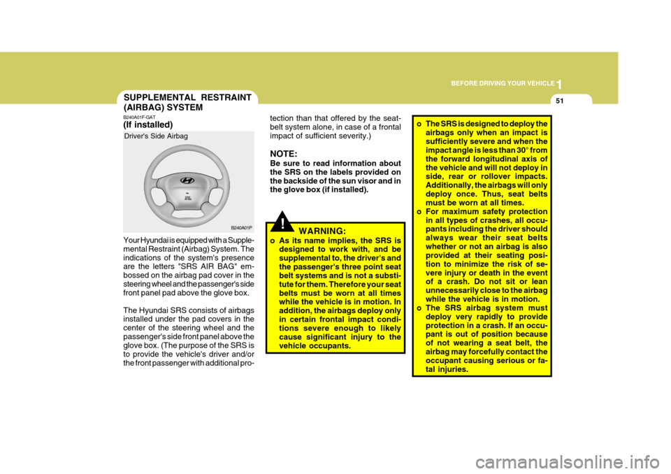
B240A01F-GAT (If installed) Your Hyundai is equipped with a Supple- mental Restraint (Airbag) System. Theindications of the system's presence are the letters "SRS AIR BAG" em- bossed on the airbag pad cover in thesteering wheel and the passenger's side front panel pad above the glove box. The Hyundai SRS consists of airbags installed under the pad covers in the center of the steering wheel and thepassenger's side front panel above the glove box. (The purpose of the SRS is to provide the vehicle's driver and/orthe front passenger with additional pro- Driver's Side Airbag
B240A01P
!
tection than that offered by the seat- belt system alone, in case of a frontalimpact of sufficient severity.) NOTE: Be sure to read information about the SRS on the labels provided onthe backside of the sun visor and in the glove box (if installed).WARNING:
o As its name implies, the SRS is designed to work with, and be supplemental to, the driver's andthe passenger's three point seat belt systems and is not a substi- tute for them. Therefore your seatbelts must be worn at all times while the vehicle is in motion. In addition, the airbags deploy onlyin certain frontal impact condi- tions severe enough to likely cause significant injury to thevehicle occupants.o The SRS is designed to deploy the
airbags only when an impact is sufficiently severe and when the impact angle is less than 30° from the forward longitudinal axis ofthe vehicle and will not deploy in side, rear or rollover impacts. Additionally, the airbags will onlydeploy once. Thus, seat belts must be worn at all times.
o For maximum safety protection
in all types of crashes, all occu-pants including the driver should always wear their seat beltswhether or not an airbag is also provided at their seating posi- tion to minimize the risk of se-vere injury or death in the event of a crash. Do not sit or lean unnecessarily close to the airbagwhile the vehicle is in motion.
o The SRS airbag system must
deploy very rapidly to provideprotection in a crash. If an occu- pant is out of position because of not wearing a seat belt, theairbag may forcefully contact the occupant causing serious or fa- tal injuries.
Page 64 of 284
1BEFORE DRIVING YOUR VEHICLE
52
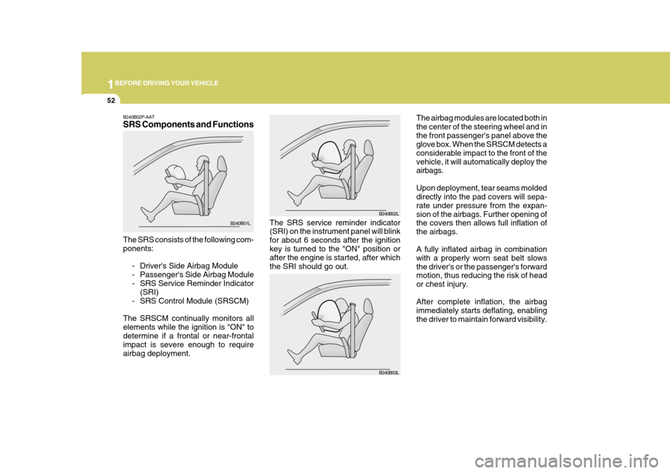
The airbag modules are located both in the center of the steering wheel and inthe front passenger's panel above the glove box. When the SRSCM detects a considerable impact to the front of thevehicle, it will automatically deploy the airbags. Upon deployment, tear seams molded directly into the pad covers will sepa- rate under pressure from the expan-sion of the airbags. Further opening of the covers then allows full inflation of the airbags. A fully inflated airbag in combination with a properly worn seat belt slowsthe driver's or the passenger's forward motion, thus reducing the risk of head or chest injury. After complete inflation, the airbag immediately starts deflating, enablingthe driver to maintain forward visibility.
The SRS service reminder indicator (SRI) on the instrument panel will blink for about 6 seconds after the ignitionkey is turned to the "ON" position or after the engine is started, after which the SRI should go out.B240B02L
B240B03L
B240B02P-AAT SRS Components and Functions The SRS consists of the following com- ponents:
- Driver's Side Airbag Module
- Passenger's Side Airbag Module
- SRS Service Reminder Indicator(SRI)
- SRS Control Module (SRSCM)
The SRSCM continually monitors allelements while the ignition is "ON" todetermine if a frontal or near-frontal impact is severe enough to require airbag deployment. B240B01L
Page 66 of 284
1BEFORE DRIVING YOUR VEHICLE
54
o For cleaning the airbag pad cov-
ers, use only a soft, dry cloth or one which has been moistened with plain water. Solvents orcleaners could adversely affect the airbag covers and proper deployment of the system.
o No objects should be placed over or near the airbag modules onthe steering wheel, instrumentpanel, and the front passenger's panel above the glove box, be- cause any such object couldcause harm if the vehicle is in a crash severe enough to cause the airbags to inflate.
o If the airbags inflate, they must be replaced by an authorizedHyundai dealer.
o Do not tamper with or discon- nect SRS wiring, or other com-ponents of the SRS system. Do-ing so could result in injury, due to accidental inflation of the airbags or by rendering the SRSinoperative.
!WARNING:
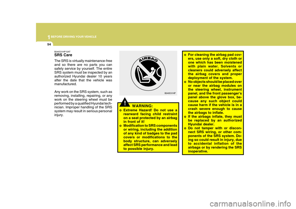
o Extreme Hazard! Do not use a rearward facing child restraint on a seat protected by an airbag in front of it!
o Modification to SRS components
or wiring, including the additionof any kind of badges to the pad covers or modifications to thebody structure, can adversely affect SRS performance and lead to possible injury. B240C01HP
B240C01HP-GAT SRS Care The SRS is virtually maintenance-free and so there are no parts you cansafely service by yourself. The entire SRS system must be inspected by an authorized Hyundai dealer 10 yearsafter the date that the vehicle was manufactured. Any work on the SRS system, such as removing, installing, repairing, or any work on the steering wheel must beperformed by a qualified Hyundai tech- nician. Improper handling of the SRS system may result in serious personalinjury.
Page 178 of 284
44IN CASE OF EMERGENCY
2
Release valve
TOOLS AND JACK
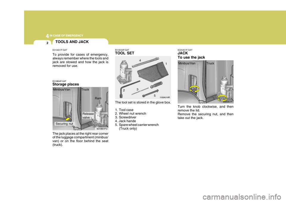
E010A01P-GAT To provide for cases of emergency, always remember where the tools and jack are stowed and how the jack is removed for use.
E010B04P-GAT Storage places E010C04P-GAT TOOL SET
E020A01P-GATJACK To use the jack
The jack places at the right rear corner of the luggage compartment (minibus/ van) or on the floor behind the seat(truck). Minibus/Van Truck
The tool set is stored in the glove box.
1. Tool case
2. Wheel nut wrench
3. Screwdriver4. Jack hande
5. Spare wheel carrier wrench(Truck only) Turn the knob clockwise, and then remove the lid. Remove the securing nut, and then take out the jack.
E010B01P-2 I100A01HR
E020A01P
Minibus/Van Truck
Securing nut
Ram 2
34
1
5
Page 229 of 284
6
VEHICLE MAINTENANCE REQUIREMENTS
3SCHEDULED MAINTE- NANCE REQUIREMENTS
F010E01P-AAT
Do-It-Yourself Maintenance
If you are mechanically inclined, own a few tools that are required and want to take the time to do so, you can inspect and service a number of items. Formore information about doing it your- self, see Section 8. F010F01A-GAT
A Few Tips
Whenever you have your Hyundai ser- viced, keep copies of the service records in your glovebox. This will help ensure that you can document that therequired procedures have been per- formed to keep your warranties in ef- fect. This is especially important whenservice is not performed by an autho- rized Hyundai dealer. F020A03S-GAT Inspection should be performed any time a malfunction is experienced or suspected. Receipts for all emissioncontrol system services should be re- tained to demonstrate compliance with conditions of the emissions systemwarranty.For severe usage maintenance require-ments, see page 6-11 of this section.