ABS Hyundai H-1 (Grand Starex) 2013 User Guide
[x] Cancel search | Manufacturer: HYUNDAI, Model Year: 2013, Model line: H-1 (Grand Starex), Model: Hyundai H-1 (Grand Starex) 2013Pages: 353, PDF Size: 9.18 MB
Page 236 of 353
545
Driving your vehicle
5. Start the vehicle, hold the brakes, shift
to neutral, release the parking brake
and slowly release the brakes until the
trailer chocks absorb the load.
6. Reapply the brakes, reapply the park-
ing brake and shift the vehicle to R
(Reverse) for manual transmission or
P (Park) automatic transmission.
7. Shut off the vehicle and release the
vehicle brakes but leave the parking
brake set.
When you are ready to leave after park-
ing on a hill
1. With the manual transmission in
Neutral or automatic transmission in P
(Park), apply your brakes and hold the
brake pedal down while you:
• Start your engine;
• Shift into gear; and
• Release the parking brake.2. Slowly remove your foot from the
brake pedal.
3. Drive slowly until the trailer is clear of
the chocks.
4. Stop and have someone pick up and
store the chocks.
E140500AUN
Maintenance when trailer towing
Your vehicle will need service more often
when you regularly pull a trailer.
Important items to pay particular atten-
tion to include engine oil, automatic
transmission fluid, axle lubricant and
cooling system fluid. Brake condition is
another important item to frequently
check. Each item is covered in this man-
ual, and the Index will help you find them
quickly. If you’re trailering, it’s a good idea
to review these sections before you start
your trip.
Don’t forget to also maintain your trailer
and hitch. Follow the maintenance
schedule that accompanied your trailer
and check it periodically. Preferably, con-
duct the check at the start of each day’s
driving. Most importantly, all hitch nuts
and bolts should be tight.
WARNING- Parking brake
It can be dangerous to get out of
your vehicle if the parking brake is
not firmly set.
If you have left the engine running,
the vehicle can move suddenly. You
or others could be seriously or
fatally injured.
CAUTION
• Due to higher load during trailer
usage, overheating might occur
in hot days or during uphill driv-
ing. If the coolant gauge indicates
over-heating, switch off the A/C
and stop the vehicle in a safe area
to cool down the engine.
• When towing check transmission
fluid more frequently.
• If your vehicle is not equipped
with the air conditioner, you
should install a condenser fan to
improve engine performance
when towing a trailer.
Page 254 of 353
615
What to do in an emergency
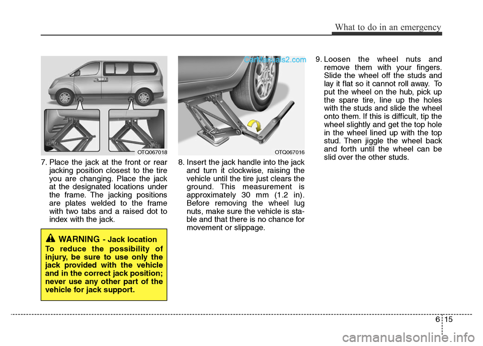
7. Place the jack at the front or rear
jacking position closest to the tire
you are changing. Place the jack
at the designated locations under
the frame. The jacking positions
are plates welded to the frame
with two tabs and a raised dot to
index with the jack.8. Insert the jack handle into the jack
and turn it clockwise, raising the
vehicle until the tire just clears the
ground. This measurement is
approximately 30 mm (1.2 in).
Before removing the wheel lug
nuts, make sure the vehicle is sta-
ble and that there is no chance for
movement or slippage.9. Loosen the wheel nuts and
remove them with your fingers.
Slide the wheel off the studs and
lay it flat so it cannot roll away. To
put the wheel on the hub, pick up
the spare tire, line up the holes
with the studs and slide the wheel
onto them. If this is difficult, tip the
wheel slightly and get the top hole
in the wheel lined up with the top
stud. Then jiggle the wheel back
and forth until the wheel can be
slid over the other studs.
WARNING- Jack location
To reduce the possibility of
injury, be sure to use only the
jack provided with the vehicle
and in the correct jack position;
never use any other part of the
vehicle for jack support.
OTQ067018OTQ067016
Page 313 of 353
749
Maintenance
G200700BUN
Wheel replacement
When replacing the metal wheels for
any reason, make sure the new
wheels are equivalent to the original
factory units in diameter, rim width
and offset.
G200800AUN
Tire traction
Tire traction can be reduced if you
drive on worn tires, tires that are
improperly inflated or on slippery
road surfaces. Tires should be
replaced when tread wear indicators
appear. To reduce the possibility of
losing control, slow down whenever
there is rain, snow or ice on the road.
G200900AUN
Tire maintenance
In addition to proper inflation, correct
wheel alignment helps to decrease
tire wear. If you find a tire is worn
unevenly, we recommend that the
wheel alignment be checked by an
authorized HYUNDAI dealer.
When you have new tires installed,
make sure they are balanced. This
will increase vehicle ride comfort and
tire life. Additionally, a tire should
always be rebalanced if it is removed
from the wheel.
(Continued)
• Using tires and wheel other
than the recommended sizes
could cause unusual handling
characteristics and poor vehi-
cle control, resulting in a seri-
ous accident.
• Wheels that do not meet
HYUNDAI’s specifications
may fit poorly and result in
damage to the vehicle or
unusual handling and poor
vehicle control.
• The ABS works by comparing
the speed of the wheels. Tire
size can affect wheel speed.
When replacing tires, all 4
tires must use the same size
originally supplied with the
vehicle. Using tires of a differ-
ent size can cause the ABS
(Anti-lock Brake System) and
ESP (Electronic Stability
Program) (if equipped) to
work irregularly.
WARNING
A wheel that is not the correct
size may adversely affect wheel
and bearing life, braking and
stopping abilities, handling
characteristics, ground clear-
ance, body-to-tire clearance,
snow chain clearance,
speedometer and odometer cal-
ibration, headlight aim and
bumper height.
Page 324 of 353
Maintenance
60 7
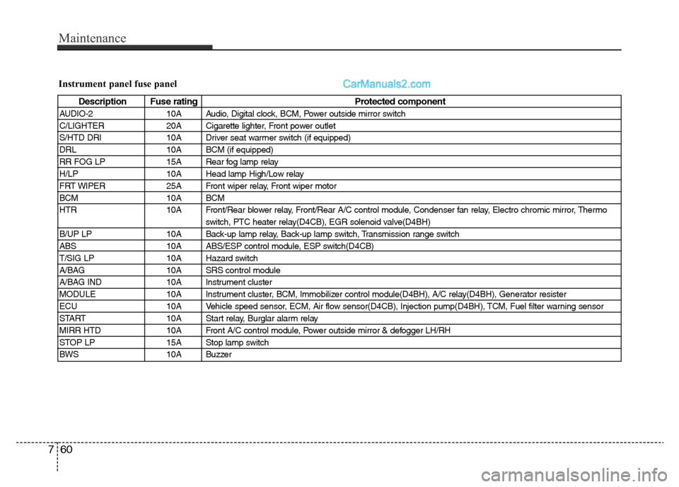
Instrument panel fuse panel
Description Fuse rating Protected component
AUDIO-2 10A Audio, Digital clock, BCM, Power outside mirror switch
C/LIGHTER 20A Cigarette lighter, Front power outlet
S/HTD DRI 10A Driver seat warmer switch (if equipped)
DRL 10A BCM (if equipped)
RR FOG LP 15A Rear fog lamp relay
H/LP 10A Head lamp High/Low relay
FRT WIPER 25A Front wiper relay, Front wiper motor
BCM 10A BCM
HTR 10A Front/Rear blower relay, Front/Rear A/C control module, Condenser fan relay, Electro chromic mirror, Thermo
switch, PTC heater relay(D4CB), EGR solenoid valve(D4BH)
B/UP LP 10A Back-up lamp relay, Back-up lamp switch, Transmission range switch
ABS 10A ABS/ESP control module, ESP switch(D4CB)
T/SIG LP 10A Hazard switch
A/BAG 10A SRS control module
A/BAG IND 10A Instrument cluster
MODULE 10A Instrument cluster, BCM, Immobilizer control module(D4BH), A/C relay(D4BH), Generator resister
ECU 10A Vehicle speed sensor, ECM, Air flow sensor(D4CB), Injection pump(D4BH), TCM, Fuel filter warning sensor
START 10A Start relay, Burglar alarm relay
MIRR HTD 10A Front A/C control module, Power outside mirror & defogger LH/RH
STOP LP 15A Stop lamp switch
BWS 10A Buzzer
Page 326 of 353
Maintenance
62 7
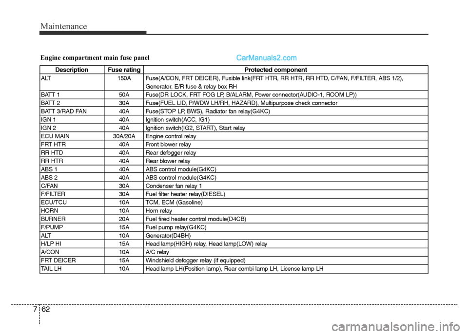
Engine compartment main fuse panel
Description Fuse rating Protected component
ALT 150A Fuse(A/CON, FRT DEICER), Fusible link(FRT HTR, RR HTR, RR HTD, C/FAN, F/FILTER, ABS 1/2),
Generator, E/R fuse & relay box RH
BATT 1 50A Fuse(DR LOCK, FRT FOG LP, B/ALARM, Power connector(AUDIO-1, ROOM LP))
BATT 2 30A Fuse(FUEL LID, P/WDW LH/RH, HAZARD), Multipurpose check connector
BATT 3/RAD FAN 40A Fuse(STOP LP, BWS), Radiator fan relay(G4KC)
IGN 1 40A Ignition switch(ACC, IG1)
IGN 2 40A Ignition switch(IG2, START), Start relay
ECU MAIN 30A/20A Engine control relay
FRT HTR 40A Front blower relay
RR HTD 40A Rear defogger relay
RR HTR 40A Rear blower relay
ABS 1 40A ABS control module(G4KC)
ABS 2 40A ABS control module(G4KC)
C/FAN 30A Condenser fan relay 1
F/FILTER 30A Fuel filter heater relay(DIESEL)
ECU/TCU 10A TCM, ECM (Gasoline)
HORN 10A Horn relay
BURNER 20A Fuel fired heater control module(D4CB)
F/PUMP 15A Fuel pump relay(G4KC)
ALT 10A Generator(D4BH)
H/LP HI 15A Head lamp(HIGH) relay, Head lamp(LOW) relay
A/CON 10A A/C relay
FRT DEICER 15A Windshield defogger relay (if equipped)
TAIL LH 10A Head lamp LH(Position lamp), Rear combi lamp LH, License lamp LH
Page 327 of 353
763
Maintenance
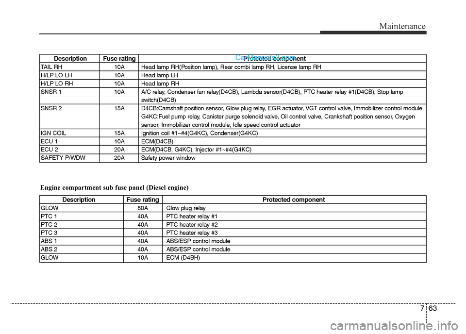
Description Fuse rating Protected component
TAIL RH 10A Head lamp RH(Position lamp), Rear combi lamp RH, License lamp RH
H/LP LO LH 10A Head lamp LH
H/LP LO RH 10A Head lamp RH
SNSR 1 10A A/C relay, Condenser fan relay(D4CB), Lambda sensor(D4CB), PTC heater relay #1(D4CB), Stop lamp
switch(D4CB)
SNSR 2 15A D4CB:Camshaft position sensor, Glow plug relay, EGR actuator, VGT control valve, Immobilizer control module
G4KC:Fuel pump relay, Canister purge solenoid valve, Oil control valve, Crankshaft position sensor, Oxygen
sensor, Immobilizer control module, Idle speed control actuator
IGN COIL 15A Ignition coil #1~#4(G4KC), Condenser(G4KC)
ECU 1 10A ECM(D4CB)
ECU 2 20A ECM(D4CB, G4KC), Injector #1~#4(G4KC)
SAFETY P/WDW 20A Safety power window
Engine compartment sub fuse panel (Diesel engine)
Description Fuse rating Protected component
GLOW 80A Glow plug relay
PTC 1 40A PTC heater relay #1
PTC 2 40A PTC heater relay #2
PTC 3 40A PTC heater relay #3
ABS 1 40A ABS/ESP control module
ABS 2 40A ABS/ESP control module
GLOW 10A ECM (D4BH)
Page 330 of 353
Maintenance
66 7
G220102ATQ
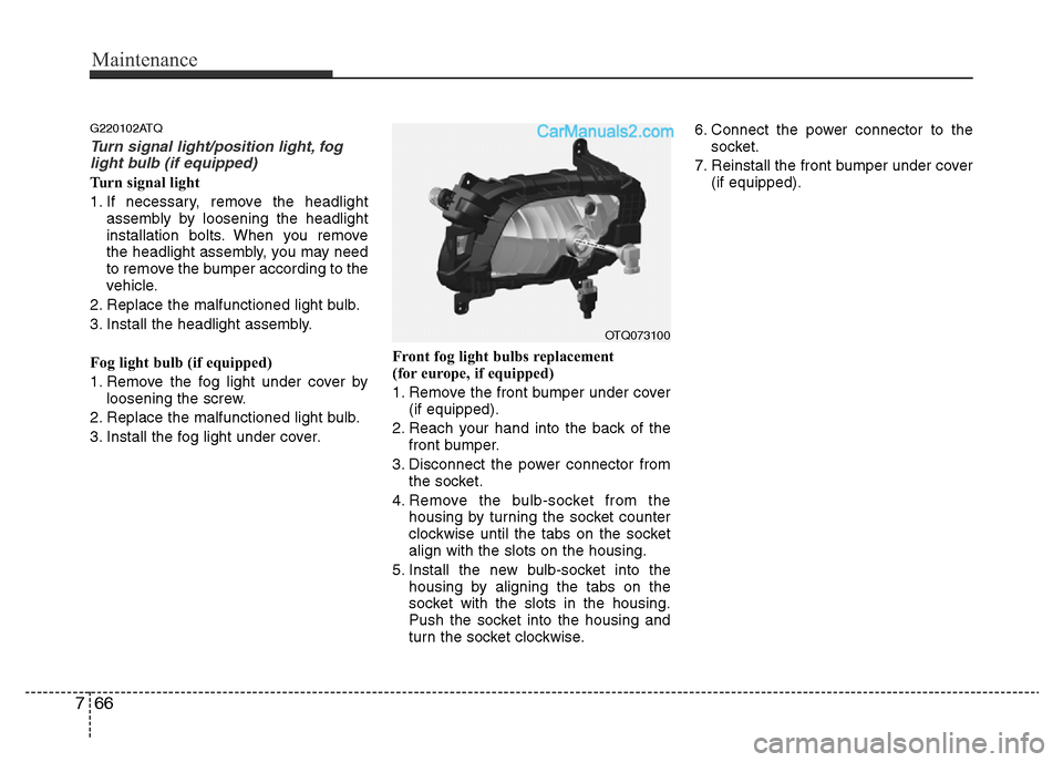
Turn signal light/position light, fog
light bulb (if equipped)
Turn signal light
1. If necessary, remove the headlight
assembly by loosening the headlight
installation bolts. When you remove
the headlight assembly, you may need
to remove the bumper according to the
vehicle.
2. Replace the malfunctioned light bulb.
3. Install the headlight assembly.
Fog light bulb (if equipped)
1. Remove the fog light under cover by
loosening the screw.
2. Replace the malfunctioned light bulb.
3. Install the fog light under cover.Front fog light bulbs replacement
(for europe, if equipped)
1. Remove the front bumper under cover
(if equipped).
2. Reach your hand into the back of the
front bumper.
3. Disconnect the power connector from
the socket.
4. Remove the bulb-socket from the
housing by turning the socket counter
clockwise until the tabs on the socket
align with the slots on the housing.
5. Install the new bulb-socket into the
housing by aligning the tabs on the
socket with the slots in the housing.
Push the socket into the housing and
turn the socket clockwise.6. Connect the power connector to the
socket.
7. Reinstall the front bumper under cover
(if equipped).
OTQ073100
Page 331 of 353
767
Maintenance
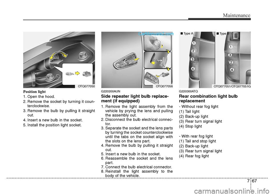
Position light
1. Open the hood.
2. Remove the socket by turning it coun-
terclockwise.
3. Remove the bulb by pulling it straight
out.
4. Insert a new bulb in the socket.
5. Install the position light socket.G220200AUN
Side repeater light bulb replace-
ment (if equipped)
1. Remove the light assembly from the
vehicle by prying the lens and pulling
the assembly out.
2. Disconnect the bulb electrical connec-
tor.
3. Separate the socket and the lens parts
by turning the socket counterclockwise
until the tabs on the socket align with
the slots on the lens part.
4. Remove the bulb by pulling it straight
out.
5. Insert a new bulb in the socket.
6. Reassemble the socket and the lens
part.
7. Connect the bulb electrical connector.
8. Reinstall the light assembly to the
body of the vehicle.
G220300ATQ
Rear combination light bulb
replacement
- Without rear fog light
(1) Tail light
(2) Back-up light
(3) Rear turn signal light
(4) Stop light
- With rear fog light
(1) Tail and stop light
(2) Back-up light
(3) Rear turn signal light
(4) Rear fog light
OTQ077050OTQ077056OTQ077051/OTQ077051G
■Type A
■Type B
Page 332 of 353
Maintenance
68 7
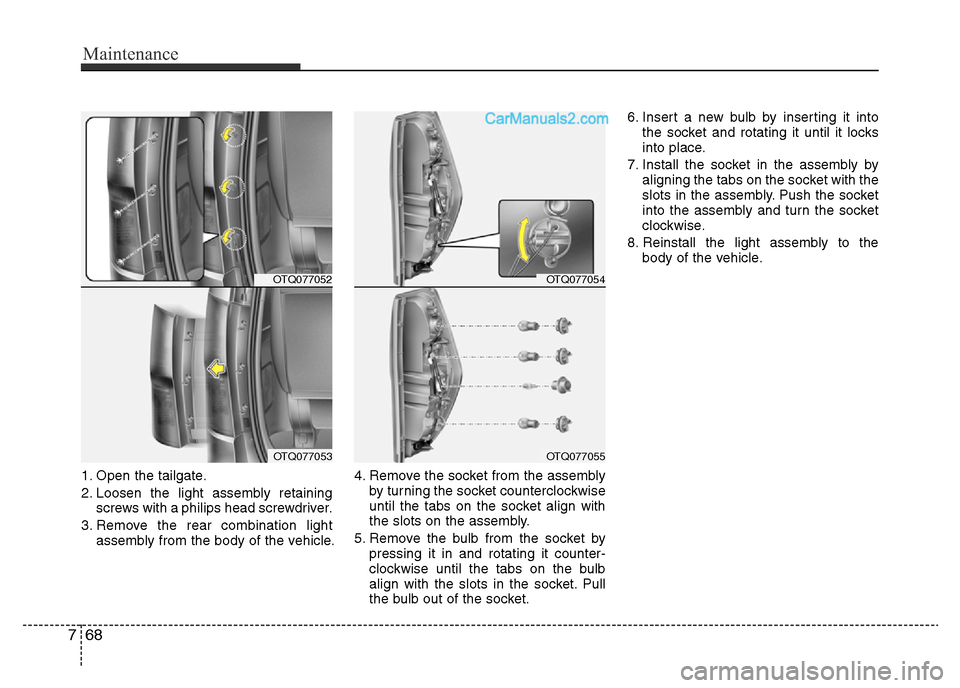
1. Open the tailgate.
2. Loosen the light assembly retaining
screws with a philips head screwdriver.
3. Remove the rear combination light
assembly from the body of the vehicle.4. Remove the socket from the assembly
by turning the socket counterclockwise
until the tabs on the socket align with
the slots on the assembly.
5. Remove the bulb from the socket by
pressing it in and rotating it counter-
clockwise until the tabs on the bulb
align with the slots in the socket. Pull
the bulb out of the socket.6. Insert a new bulb by inserting it into
the socket and rotating it until it locks
into place.
7. Install the socket in the assembly by
aligning the tabs on the socket with the
slots in the assembly. Push the socket
into the assembly and turn the socket
clockwise.
8. Reinstall the light assembly to the
body of the vehicle.
OTQ077054
OTQ077055
OTQ077052
OTQ077053
Page 334 of 353
Maintenance
70 7
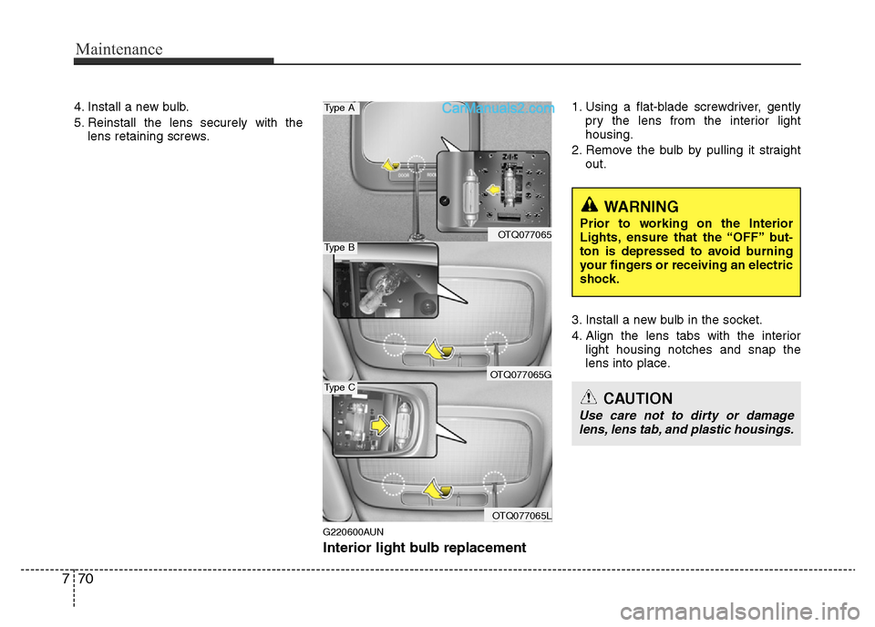
4. Install a new bulb.
5. Reinstall the lens securely with the
lens retaining screws.
G220600AUN
Interior light bulb replacement
1. Using a flat-blade screwdriver, gently
pry the lens from the interior light
housing.
2. Remove the bulb by pulling it straight
out.
3. Install a new bulb in the socket.
4. Align the lens tabs with the interior
light housing notches and snap the
lens into place.
WARNING
Prior to working on the Interior
Lights, ensure that the “OFF” but-
ton is depressed to avoid burning
your fingers or receiving an electric
shock.
CAUTION
Use care not to dirty or damage
lens, lens tab, and plastic housings.
OTQ077065
OTQ077065G
OTQ077065L
Type A
Type B
Type C