wheel torque Hyundai H350 2015 Owner's Manual
[x] Cancel search | Manufacturer: HYUNDAI, Model Year: 2015, Model line: H350, Model: Hyundai H350 2015Pages: 473, PDF Size: 26.4 MB
Page 298 of 473
5-27
Driving your vehicle
5
VDC OFF usage
When Driving
The VDC OFF mode should only be
used briefly to help free the vehicle if
stuck in snow or mud by temporarily
stopping operation of the VDC to
maintain wheel torque.
To turn VDC off while driving, press
the VDC OFF button while driving on
a flat road surface.To prevent damage to thetransaxle:
Do not allow wheel(s) of one
axle to spin excessively while
the VDC, ABS, and brake warn-
ing lights are displayed. The
repairs would not be covered by
the vehicle warranty. Reduce
engine power and do not spin
the wheel(s) excessively while
these lights are displayed.
When operating the vehicle on a dynamometer, ensure the VDC isturned off (VDC OFF light illumi-nated).
Information
Turning the VDC off does not affect
ABS or standard brake system opera-
tion.
Hill-Start Assist Control (HAC) (if equipped)
The Hill-Start Assist Control (HAC)
prevents the vehicle from rolling
backwards when starting a vehicle
from a stop on a hill. The system
operates the brakes automatically for
approximately 2 seconds and releas-
es the brake when the acceleratorpedal is depressed or after 2 sec-
onds.
i
NOTICE
Always be ready to depress the
accelerator pedal when starting
off on an incline. The HAC acti-
vates only for approximately 2seconds.
WARNING
Page 334 of 473
5-63
Driving your vehicle
5
GVWR (Gross vehicle weight rating)
This is the maximum allowable
weight of the fully loaded vehicle
(including all options, equipment,
passengers and cargo). The GVWR
is shown on the certification label.
Overloading
A locking differential, if equipped, is
for the rear wheel differential only.
The features of this locking differen-
tial are described below:
Just as with a conventional differen-
tial, the wheel on one side is allowed
to turn at a different speed from thewheel on the other side when the
vehicle is cornering. The difference
between the locking differential and a
conventional differential is that if the
wheel on one side of the vehicle
loses traction, a greater amount oftorque is applied to the rear wheel on
the other side to improve traction.Information
In a stationary position, the LD
(Locking Differential) will operate
when the difference of the revolution
speed between the rear right wheel
and the rear left wheel occurs.
i
The gross axle weight rating
(GAWR) and the gross vehicle
weight rating (GVWR) for your
vehicle are on the certification
label attached to the driver's (or
front passenger’s) door.Exceeding these ratings can
cause an accident or vehicle
damage. You can calculate the
weight of your load by weighing
the items (and people) before
putting them in the vehicle. Be
careful not to overload your
vehicle.
WARNING
LL OO CCKK IINN GG DD IIFF FFEE RR EENN TTIIAA LL
(
( IIFF EE QQ UUIIPP PP EEDD ))
Page 348 of 473
6-13
What to do in an emergency
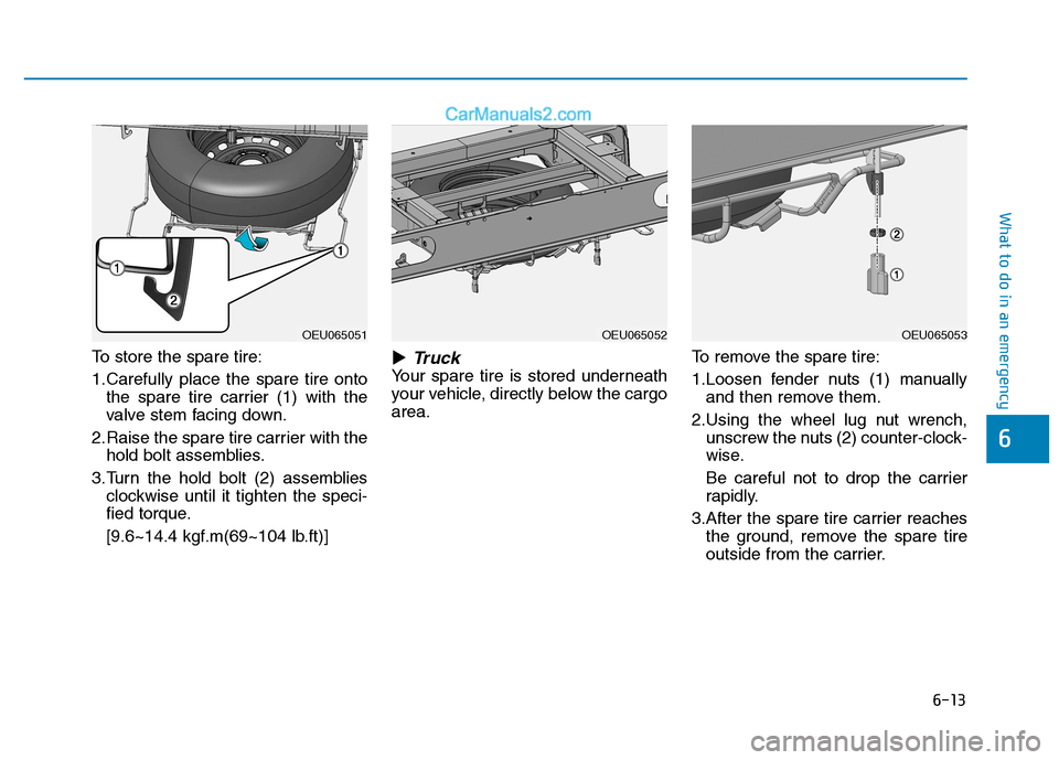
To store the spare tire:
1.Carefully place the spare tire ontothe spare tire carrier (1) with the
valve stem facing down.
2.Raise the spare tire carrier with the hold bolt assemblies.
3.Turn the hold bolt (2) assemblies clockwise until it tighten the speci-
fied torque.
[9.6~14.4 kgf.m(69~104 lb.ft)] �Truck
Your spare tire is stored underneath
your vehicle, directly below the cargoarea.
To remove the spare tire:
1.Loosen fender nuts (1) manually
and then remove them.
2.Using the wheel lug nut wrench, unscrew the nuts (2) counter-clock-
wise.
Be careful not to drop the carrier
rapidly.
3.After the spare tire carrier reaches the ground, remove the spare tire
outside from the carrier.
6
OEU065051OEU065052OEU065053
Page 349 of 473
6-14
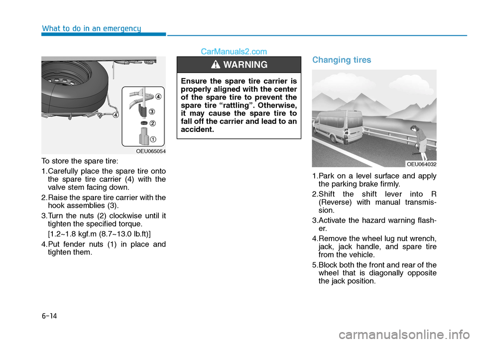
To store the spare tire:
1.Carefully place the spare tire onto
the spare tire carrier (4) with the
valve stem facing down.
2.Raise the spare tire carrier with the hook assemblies (3).
3.Turn the nuts (2) clockwise until it tighten the specified torque.
[1.2~1.8 kgf.m (8.7~13.0 lb.ft)]
4.Put fender nuts (1) in place and tighten them.
Changing tires
1.Park on a level surface and applythe parking brake firmly.
2.Shift the shift lever into R (Reverse) with manual transmis- sion.
3.Activate the hazard warning flash- er.
4.Remove the wheel lug nut wrench, jack, jack handle, and spare tire
from the vehicle.
5.Block both the front and rear of the wheel that is diagonally opposite
the jack position.
What to do in an emergency
OEU065054
OEU064032
Ensure the spare tire carrier is
properly aligned with the center
of the spare tire to prevent the
spare tire “rattling”. Otherwise,
it may cause the spare tire tofall off the carrier and lead to anaccident.
WARNING
Page 354 of 473
6-19
What to do in an emergency
6
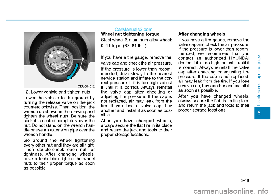
12. Lower vehicle and tighten nuts
Lower the vehicle to the ground by
turning the release valve on the jack
counterclockwise. Then position the
wrench as shown in the drawing and
tighten the wheel nuts. Be sure the
socket is seated completely over the
nut. Do not stand on the wrench han-
dle or use an extension pipe over the
wrench handle. Go around the wheel tightening
every other nut until they are all tight.
Then double-check each nut for
tightness. After changing wheels,
have a technician tighten the wheel
nuts to their proper torque as soon
as possible.Wheel nut tightening torque:
Steel wheel & aluminum alloy wheel:
9~11 kg.m (67~81 lb.ft)
If you have a tire gauge, remove the
valve cap and check the air pressure.
If the pressure is lower than recom-
mended, drive slowly to the nearest
service station and inflate to the cor-
rect pressure. If it is too high, adjust
it until it is correct. Always reinstall
the valve cap after checking or
adjusting tire pressure. If the cap is
not replaced, air may leak from the
tire. If you lose a valve cap, buyanother and install it as soon as pos-
sible.
After you have changed wheels,
always secure the flat tire in its place
and return the jack and tools to their
proper storage locations.
After changing wheels
If you have a tire gauge, remove the
valve cap and check the air pressure.
If the pressure is lower than recom-
mended, we recommend that you
contact an authorized HYUNDAI
dealer. If it is too high, adjust it until it
is correct. Always reinstall the valve
cap after checking or adjusting tire
pressure. If the cap is not replaced,
air may leak from the tire. If you lose
a valve cap, buy another and install it
as soon as possible.
After you have changed wheels,
always secure the flat tire in its place
and return the jack and tools to their
proper storage locations.
OEU064012
Page 384 of 473
7-21
7
Maintenance
Coolant
The coolant should be changed at
the intervals specified in the mainte-
nance schedule.
Manual transmission fluid (if equipped)
Inspect the manual transmission fluid according to the maintenance
schedule.
Brake hoses and lines
Visually check for proper installation,
chafing, cracks, deterioration and
any leakage. Replace any deteriorat-
ed or damaged parts immediately.
Brake fluid
Check brake fluid level in the brake
fluid reservoir. The level should be
between “MIN” and “MAX” marks on
the side of the reservoir. Use only
hydraulic brake fluid conforming to
DOT 4 specification.
Parking brake
Inspect the parking brake system
including the parking brake lever and
cables.
Brake discs, pads, calipers
and rotors
Check the pads for excessive wear,
discs for run out and wear, and
calipers for fluid leakage.
For more information on checking
the pads or lining wear limit, refer to
the HYUNDAI web site. (http://brakeman
ual.hmc.co.kr)
Suspension mounting bolts
Check the suspension connections
for looseness or damage. Retighten
to the specified torque.
Steering gear box, linkage &
boots/lower arm ball joint
With the vehicle stopped and engine
off, check for excessive free-play in
the steering wheel.
Check the linkage for bends or dam-
age. Check the dust boots and ball
joints for deterioration, cracks, or
damage. Replace any damaged
parts.
Power steering pump, belt and hoses
Check the power steering pump and
hoses for leakage and damage.
Replace any damaged or leaking
parts immediately. Inspect the power
steering belt (or drive belt) for evi-
dence of cuts, cracks, excessive
wear, oiliness and proper tension.
Replace or adjust it if necessary.
Air conditioning refrigerant (if equipped)
Check the air conditioning lines and
connections for leakage and dam-
age.
Page 458 of 473
8-5
8
Specifications & Consumer information
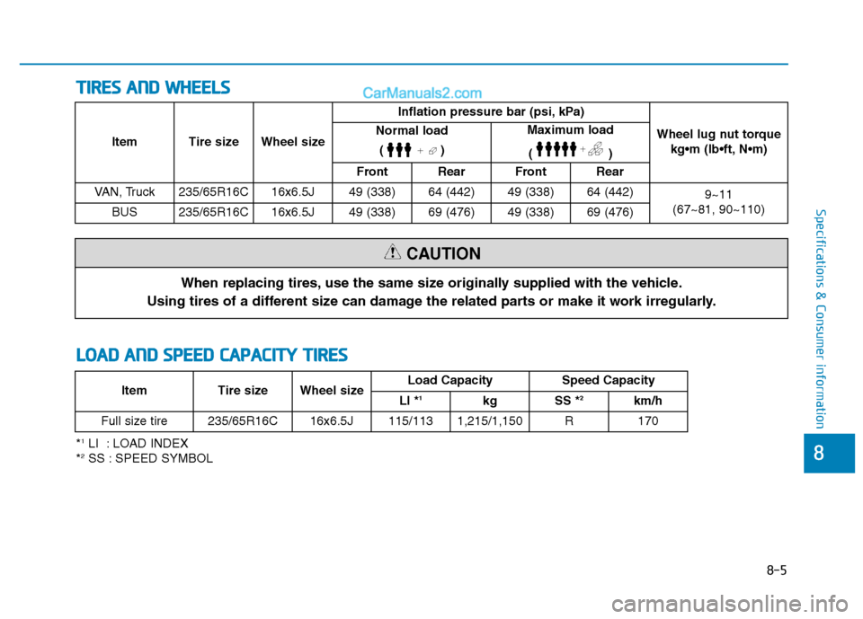
TTIIRR EESS AA NN DD WW HHEEEELLSS
When replacing tires, use the same size originally supplied with the vehicle.
Using tires of a different size can damage the related parts or make it work irregularly.
CAUTION
LL OO AADD AA NN DD SS PP EEEEDD CC AA PPAA CCIITT YY TT IIRR EESS
Item Tire size Wheel size Inflation pressure bar (psi, kPa)
Wheel lug nut torquekg•m (lb N
Normal load
()Maximum load
()
Front Rear Front Rear
VAN, Truck 235/65R16C 16x6.5J 49 (338) 64 (442) 49 (338) 64 (442) 9~11
(67~81, 90~110)
BUS 235/65R16C 16x6.5J 49 (338) 69 (476) 49 (338) 69 (476)
* 1
LI : LOAD INDEX
* 2
SS : SPEED SYMBOL Item Tire size Wheel size
Load Capacity Speed Capacity
LI * 1
kg SS * 2
km/h
Full size tire 235/65R16C 16x6.5J 115/113 1,215/1,150 R 170