light HYUNDAI I10 2010 Owners Manual
[x] Cancel search | Manufacturer: HYUNDAI, Model Year: 2010, Model line: I10, Model: HYUNDAI I10 2010Pages: 354, PDF Size: 37.04 MB
Page 308 of 354
Maintenance
46
7
G200601AUN
Compact spare tire replacement (if
equipped)
A compact spare tire has a shorter
tread life than a regular size tire.
Replace it when you can see the
tread wear indicator bars on the tire.The replacement compact spare tire
should be the same size and design
tire as the one provided with your
new vehicle and should be mountedon the same compact spare tire
wheel. The compact spare tire is notdesigned to be mounted on a regular
size wheel, and the compact spare
tire wheel is not designed for mount-
ing a regular size tire. G200700BUN Wheel replacement
When replacing the metal wheels for
any reason, make sure the new
wheels are equivalent to the original
factory units in diameter, rim widthand offset.
G200800AUN Tire traction
Tire traction can be reduced if you
drive on worn tires, tires that are
improperly inflated or on slippery
road surfaces. Tires should be
replaced when tread wear indicators
appear. To reduce the possibility of
losing control, slow down whenever
there is rain, snow or ice on the road.
G200900AUN Tire maintenance In addition to proper inflation, correct wheel alignment helps to decrease
tire wear. If you find a tire is worn
unevenly, have your dealer check thewheel alignment.
When you have new tires installed,
make sure they are balanced. This
will increase vehicle ride comfort and
tire life. Additionally, a tire should
always be rebalanced if it is removedfrom the wheel.
WARNING
A wheel that is not the correct
size may adversely affect wheel
and bearing life, braking and
stopping abilities, handling
characteristics, ground clear-
ance, body-to-tire clearance,
snow chain clearance,speedometer and odometer cal-
ibration, headlight aim and
bumper height.
Page 313 of 354
751
Maintenance
FUSES
G210000APA
A vehicle’s electrical system is protected
from electrical overload damage by
fuses. This vehicle has 2 (or 3) fuse panels, one
located in the driver’s side panel bolster,
the other(s) in the engine compartment.
If any of your vehicle’s lights, acces-
sories, or controls do not work, check the
appropriate circuit fuse. If a fuse has
blown, the element inside the fuse will bemelted.
If the electrical system does not work,
first check the driver’s side fuse panel.
Always replace a blown fuse with one of
the same rating.
If the replacement fuse blows, this indi-
cates an electrical problem. Avoid using
the system involved and immediately
consult an authorized HYUNDAI dealer.
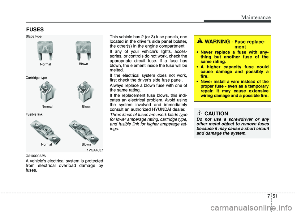
Three kinds of fuses are used: blade type
for lower amperage rating, cartridge type,
and fusible link for higher amperage rat- ings.
1VQA4037
Normal
Normal
Blade type
Cartridge type
Fusible link Blown
Blown
Normal Blown
WARNING - Fuse replace-
ment
Never replace a fuse with any- thing but another fuse of the same rating.
A higher capacity fuse could cause damage and possibly a
fire.
Never install a wire instead of the proper fuse - even as a temporary
repair. It may cause extensive
wiring damage and a possible fire.
CAUTION
Do not use a screwdriver or any
other metal object to remove fuses because it may cause a short circuitand damage the system.
Page 314 of 354
Maintenance
52
7
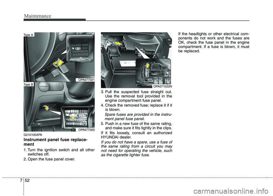
G210100APA Instrument panel fuse replace- ment
1. Turn the ignition switch and all other
switches off.
2. Open the fuse panel cover. 3. Pull the suspected fuse straight out.
Use the removal tool provided in the
engine compartment fuse panel.
4. Check the removed fuse; replace it if it is blown.
Spare fuses are provided in the instru-
ment panel fuse panel.
5. Push in a new fuse of the same rating, and make sure it fits tightly in the clips.
If it fits loosely, consult an authorized
HYUNDAI dealer.
If you do not have a spare, use a fuse of the same rating from a circuit you maynot need for operating the vehicle, suchas the cigarette lighter fuse.
If the headlights or other electrical com-
ponents do not work and the fuses are
OK, check the fuse panel in the engine
compartment. If a fuse is blown, it mustbe replaced.
OPA071022N
OPA077021
OPA077020
Type A
Type B
Page 315 of 354
753
Maintenance
G210101AUN
Memory fuse
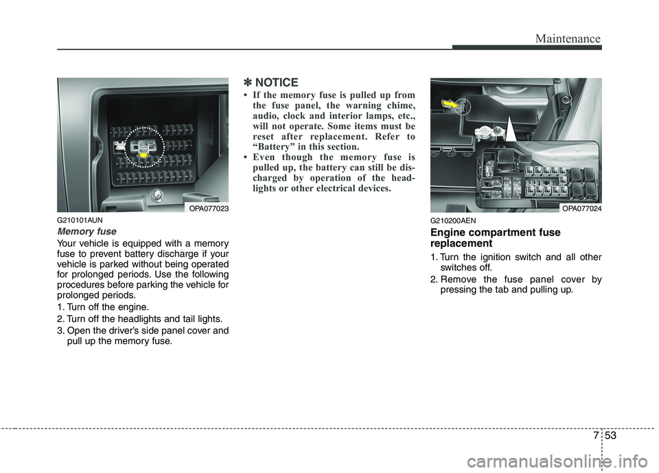
Your vehicle is equipped with a memory
fuse to prevent battery discharge if your
vehicle is parked without being operated
for prolonged periods. Use the following
procedures before parking the vehicle for
prolonged periods.
1. Turn off the engine.
2. Turn off the headlights and tail lights.
3. Open the driver’s side panel cover andpull up the memory fuse.
✽✽ NOTICE
If the memory fuse is pulled up from the fuse panel, the warning chime,
audio, clock and interior lamps, etc.,
will not operate. Some items must be
reset after replacement. Refer to
“Battery” in this section.
Even though the memory fuse is
pulled up, the battery can still be dis-
charged by operation of the head-
lights or other electrical devices.
G210200AEN
Engine compartment fuse replacement
1. Turn the ignition switch and all other switches off.
2. Remove the fuse panel cover by pressing the tab and pulling up.
OPA077023OPA077024
Page 319 of 354
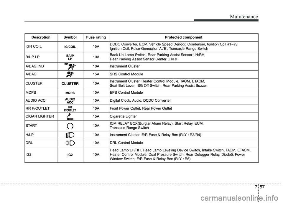
757
Maintenance
Descrption Symbol Fuse ratingProtected component
IGN COIL
15A DCDC Converter, ECM, Vehicle Speed Dendor, Condenser, Ignition Coil #1~#3,
Ignition Coil, Pulse Generator 'A'/'B', Transaxle Range Switch
B/UP LP
10A Back-Up Lamp Switch, Rear Parking Assist Sensor LH/RH,
Rear Parking Assist Sensor Center LH/RH
A/BAG IND
10A Instrument Cluster
A/BAG
15A SRS Control Module
CLUSTER
10A Instrument Cluster, Heater Control Module, TACM, ETACM,
Seat Belt Lever, ISG Off Switch, Rear Parking Assist Buzzer
MDPS
10A EPS Control Module
AUDIO ACC
10A Digital Clock, Audio, DCDC Converter
RR P/OUTLET
10A Front Power Outlet, Rear Power Outlet
CIGAR LIGHTER
15A Cigarette Lighter
START
10A ICM RELAY BOX(Burglar Alram Relay), Start Relay, ECM,
Transaxle Range Switch
H/LP
10A Instrument Cluster, E/R Fuse & Relay Box (RLY : R3/R4)
DRL
10A DRL Control Module
IG2
10A Head Lamp LH/RH, Head Lamp Leveling Device Switch, Intake Switch, TACM, ETACM,
Heater Control Module, Dual Pressure Switch, Rear Defogger Relay, Diode5, Power
Window Switch, E/R Fuse & Relay Box (RLY : R6)
Page 325 of 354
763
Maintenance
LIGHT BULBS
G220000AEN
Use only the bulbs of the specified wattage.
✽✽ NOTICE
After heavy, driving rain or washing,
headlight and taillight lenses could
appear frosty. This condition is caused by
the temperature difference between the
lamp inside and outside. This is similar
to the condensation on your windows
inside your vehicle during the rain and
doesn’t indicate a problem with your
vehicle. If the water leaks into the lamp
bulb circuitry, have the vehicle checked
by an authorized HYUNDAI dealer.
G220100AUN
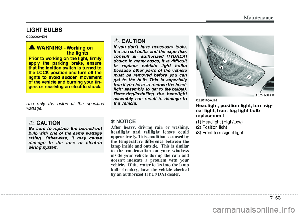
Headlight, position light, turn sig-
nal light, front fog light bulbreplacement
(1) Headlight (High/Low)
(2) Position light
(3) Front turn signal light
WARNING - Working on
the lights
Prior to working on the light, firmly
apply the parking brake, ensure
that the ignition switch is turned tothe LOCK position and turn off the
lights to avoid sudden movement
of the vehicle and burning your fin-
gers or receiving an electric shock.
CAUTION
Be sure to replace the burned-out bulb with one of the same wattage
rating. Otherwise, it may cause damage to the fuse or electricwiring system.
CAUTION
If you don’t have necessary tools,the correct bulbs and the expertise,
consult an authorized HYUNDAIdealer. In many cases, it is difficultto replace vehicle light bulbs because other parts of the vehicle
must be removed before you canget to the bulb. This is especiallytrue if you have to remove the head-
light assembly to
get to the bulb(s).
Removing/installingthe headlight
assembly can result in damage to the vehicle.OPA071033
Page 326 of 354
Maintenance
64
7
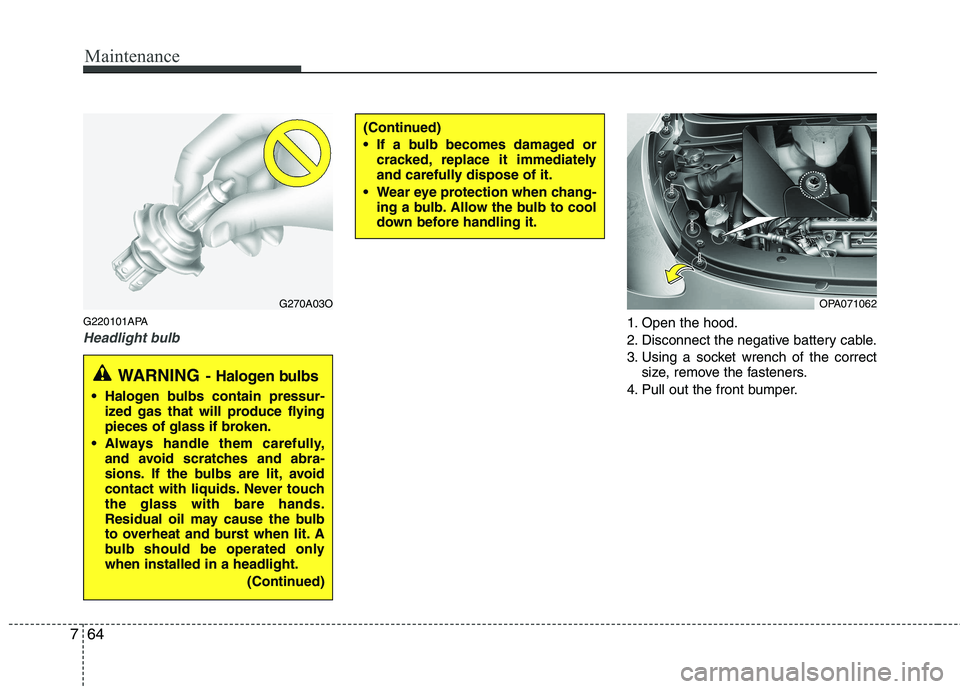
G220101APA
Headlight bulb1. Open the hood.
2. Disconnect the negative battery cable.
3. Using a socket wrench of the correct
size, remove the fasteners.
4. Pull out the front bumper.
(Continued)
If a bulb becomes damaged or cracked, replace it immediately
and carefully dispose of it.
Wear eye protection when chang- ing a bulb. Allow the bulb to cool
down before handling it.
G270A03O
WARNING - Halogen bulbs
Halogen bulbs contain pressur-
ized gas that will produce flying
pieces of glass if broken.
Always handle them carefully, and avoid scratches and abra-
sions. If the bulbs are lit, avoid
contact with liquids. Never touchthe glass with bare hands.
Residual oil may cause the bulb
to overheat and burst when lit. A
bulb should be operated onlywhen installed in a headlight.
(Continued)
OPA071062
Page 327 of 354
765
Maintenance
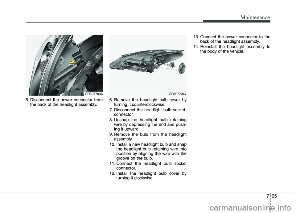
5. Disconnect the power connector fromthe back of the headlight assembly. 6. Remove the headlight bulb cover by
turning it counterclockwise.
7. Disconnect the headlight bulb socket- connector.
8. Unsnap the headlight bulb retaining wire by depressing the end and push-
ing it upward.
9. Remove the bulb from the headlight assembly.
10. Install a new headlight bulb and snap the headlight bulb retaining wire into
position by aligning the wire with the
groove on the bulb.
11. Connect the headlight bulb socket connector.
12. Install the headlight bulb cover by turning it clockwise. 13. Connect the power connector to the
back of the headlight assembly.
14. Reinstall the headlight assembly to the body of the vehicle.
OPA077036OPA077047
Page 328 of 354
Maintenance
66
7
Position light bulb
1. Remove the socket from the assembly
by pulling it out.
2. Remove the bulb by pulling it straight out.
3. Insert a new bulb into the socket.
4. Install the socket into the assembly by pushing it in.
Turn signal light bulb
1. Remove the socket from the assembly by turning the socket counter clock-
wise until the tabs on the socket align
with the slots on the assembly.
2. Remove the bulb from the socket by pressing it in and rotating it until the
tabs on the bulb align with the slots in
the socket. Pull the bulb out of the
socket.
3. Insert a new bulb by inserting it into the socket and rotating it until it locks
into place.
4. Install the socket into the assembly by aligning the tabs on the socket with the
slots in the assembly. Push the socket
into the assembly and turn the socket
clockwise. G220102APA
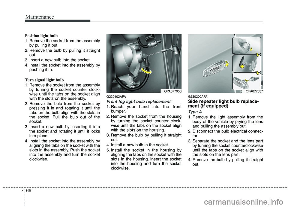
Front fog light bulb replacement
1. Reach your hand into the front
bumper.
2. Remove the socket from the housing by turning the socket counter clock-
wise until the tabs on the socket alignwith the slots on the housing.
3. Remove the bulb by pulling it straight out.
4. Install a new bulb in the socket.
5. Install the socket in the housing by aligning the tabs on the socket with the
slots in the housing. Insert the socket
into the housing and turn the socket
clockwise. G220200APA
Side repeater light bulb replace- ment (if equipped)
Type A
1. Remove the light assembly from the
body of the vehicle by prying the lens
and pulling the assembly out.
2. Disconnect the bulb electrical connec- tor.
3. Separate the socket and the lens part by turning the socket counterclockwise
until the tabs on the socket align with
the slots on the lens part.
4. Remove the bulb by pulling it straight out.
OPA077037OPA077056
Page 329 of 354
767
Maintenance
5. Insert a new bulb in the socket.
6. Reassemble the socket and the lenspart.
7. Connect the bulb electrical connector.
8. Reinstall the light assembly to the body of the vehicle.
Type B
If the light bulb is not operating, have the
vehicle checked by an authorized
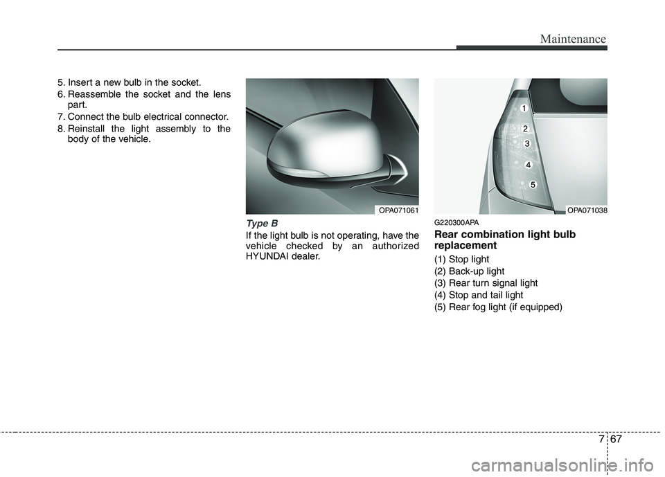
HYUNDAI dealer. G220300APA
Rear combination light bulb replacement (1) Stop light
(2) Back-up light
(3) Rear turn signal light(4) Stop and tail light
(5) Rear fog light (if equipped)
OPA071038OPA071061