HYUNDAI I10 2011 Owners Manual
Manufacturer: HYUNDAI, Model Year: 2011, Model line: I10, Model: HYUNDAI I10 2011Pages: 354, PDF Size: 37.04 MB
Page 131 of 354
Features of your vehicle
52
4
Listed below are the examples of proper
switch settings. For loading conditions
other than those listed below, adjust the
switch position so that the beam level
may be the nearest as the conditionobtained according to the list.
D200100APA
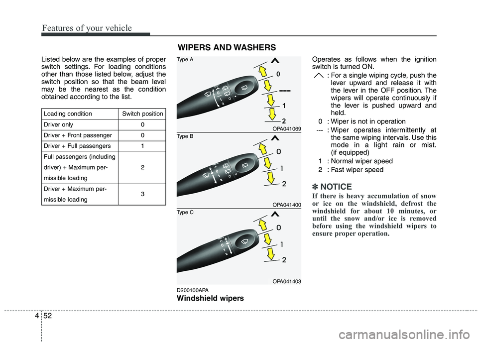
Windshield wipers Operates as follows when the ignition
switch is turned ON.
: For a single wiping cycle, push thelever upward and release it with
the lever in the OFF position. The
wipers will operate continuously if
the lever is pushed upward andheld.
0 : Wiper is not in operation
--- : Wiper operates intermittently at the same wiping intervals. Use this
mode in a light rain or mist.(if equipped)
1 : Normal wiper speed
2 : Fast wiper speed
✽✽ NOTICE
If there is heavy accumulation of snow
or ice on the windshield, defrost the
windshield for about 10 minutes, or
until the snow and/or ice is removed
before using the windshield wipers to
ensure proper operation.
Loading condition
Driver only
Driver + Front passenger
Driver + Full passengers Full passengers (including
driver) + Maximum per-
missible loading
Driver + Maximum per-
missible loading Switch position
001 2 3
OPA041069
OPA041400
OPA041403
Type B
Type A
Type C
WIPERS AND WASHERS
Page 132 of 354
453
Features of your vehicle
D200200AUN
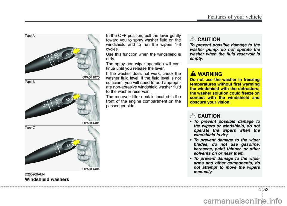
Windshield washers In the OFF position, pull the lever gently
toward you to spray washer fluid on the
windshield and to run the wipers 1-3
cycles. Use this function when the windshield is
dirty.
The spray and wiper operation will con-
tinue until you release the lever.
If the washer does not work, check the
washer fluid level. If the fluid level is not
sufficient, you will need to add appropri-
ate non-abrasive windshield washer fluid
to the washer reservoir.
The reservoir filler neck is located in the
front of the engine compartment on the
passenger side.
CAUTION
To prevent possible damage to the
washer pump, do not operate the
washer when the fluid reservoir is empty.
WARNING
Do not use the washer in freezing
temperatures without first warming
the windshield with the defrosters;
the washer solution could freeze oncontact with the windshield and
obscure your vision.
CAUTION
To prevent possible damage to the wipers or windshield, do not
operate the wipers when thewindshield is dry.
To prevent damage to the wiper blades, do not use gasoline,
kerosene, paint thinner, or othersolvents on or near them.
To prevent damage to the wiper arms and other components, do
not attempt to move the wipersmanually.
OPA041070
OPA041401
OPA041404
Type B
Type A
Type C
Page 133 of 354
Features of your vehicle
54
4
D200300APA
Rear window wiper and washer
switch (if equipped)
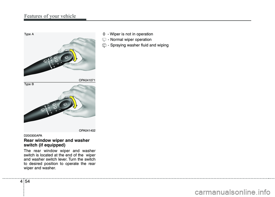
The rear window wiper and washer
switch is located at the end of the wiper
and washer switch lever. Turn the switch
to desired position to operate the rear
wiper and washer. 0 - Wiper is not in operation
- Normal wiper operation
- Spraying washer fluid and wiping
OPA041071
OPA041402
Type A
Type B
Page 134 of 354
455
Features of your vehicle
D210000AEN
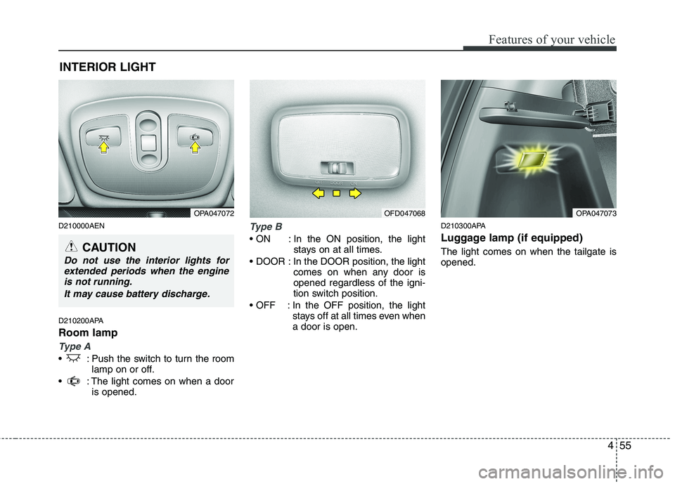
D210200APA Room lamp
Type A
: Push the switch to turn the roomlamp on or off.
: The light comes on when a door is opened.
Type B
In the ON position, the light stays on at all times.
In the DOOR position, the light comes on when any door is opened regardless of the igni-
tion switch position.
In the OFF position, the light stays off at all times even whena door is open. D210300APA
Luggage lamp (if equipped) The light comes on when the tailgate is opened.
INTERIOR LIGHT
CAUTION
Do not use the interior lights for
extended periods when the engineis not running.
It may cause battery discharge.
OPA047072OPA047073OFD047068
Page 135 of 354
Features of your vehicle
56
4
D220000APA
✽✽
NOTICE
If you want to defrost and defog the
front windshield, refer to “Windshield
defrosting and defogging” in this sec-
tion. D220100AEN
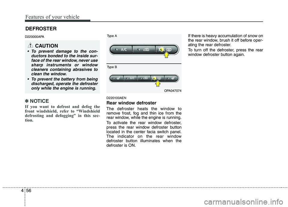
Rear window defroster
The defroster heats the window to
remove frost, fog and thin ice from the
rear window, while the engine is running.
To activate the rear window defroster,
press the rear window defroster button
located in the center facia switch panel.
The indicator on the rear window
defroster button illuminates when thedefroster is ON. If there is heavy accumulation of snow on
the rear window, brush it off before oper-
ating the rear defroster.
To turn off the defroster, press the rear
window defroster button again.
CAUTION
To prevent damage to the con-
ductors bonded to the inside sur-face of the rear window, never use
sharp instruments or windowcleaners containing abrasives to clean the window.
To prevent the battery from being discharged, operate the defrosteronly while the engine is running.
OPA047074
Type A
Type B
DEFROSTER
Page 136 of 354
457
Features of your vehicle
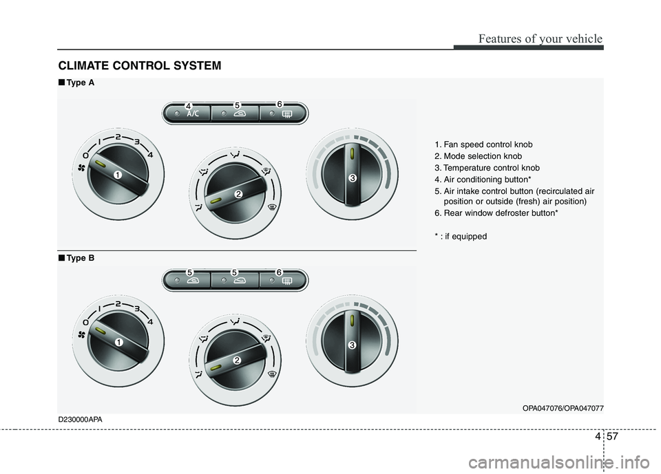
CLIMATE CONTROL SYSTEM
OPA047076/OPA047077
1. Fan speed control knob
2. Mode selection knob
3. Temperature control knob
4. Air conditioning button*
5. Air intake control button (recirculated air
position or outside (fresh) air position)
6. Rear window defroster button*
* : if equipped
D230000APA
■■ Type A
■
■ Type B
Page 137 of 354
Features of your vehicle
58
4
OPA047078/OPA047079
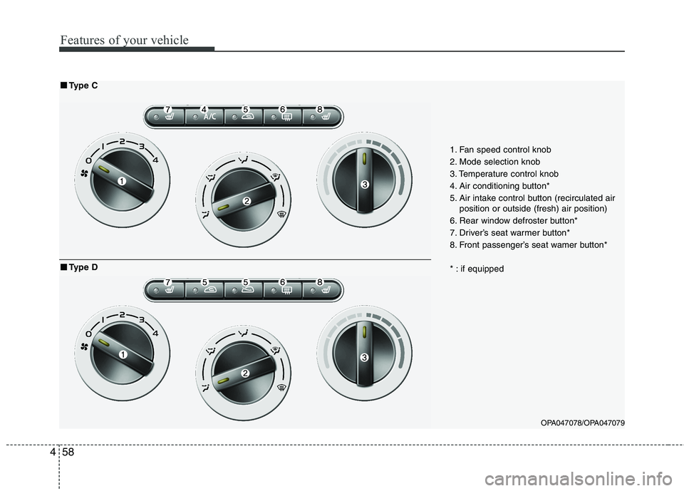
1. Fan speed control knob
2. Mode selection knob
3. Temperature control knob
4. Air conditioning button*
5. Air intake control button (recirculated air
position or outside (fresh) air position)
6. Rear window defroster button*
7. Driver’s seat warmer button*
8. Front passenger’s seat wamer button*
* : if equipped
■■ Type C
■
■ Type D
Page 138 of 354
459
Features of your vehicle
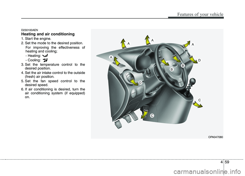
D230100AEN Heating and air conditioning
1. Start the engine.
2. Set the mode to the desired position.For improving the effectiveness of heating and cooling;- Heating: - Cooling:
3. Set the temperature control to the desired position.
4. Set the air intake control to the outside (fresh) air position.
5. Set the fan speed control to the desired speed.
6. If air conditioning is desired, turn the air conditioning system (if equipped) on.
OPA047080
Page 139 of 354
Features of your vehicle
60
4
D230101APA
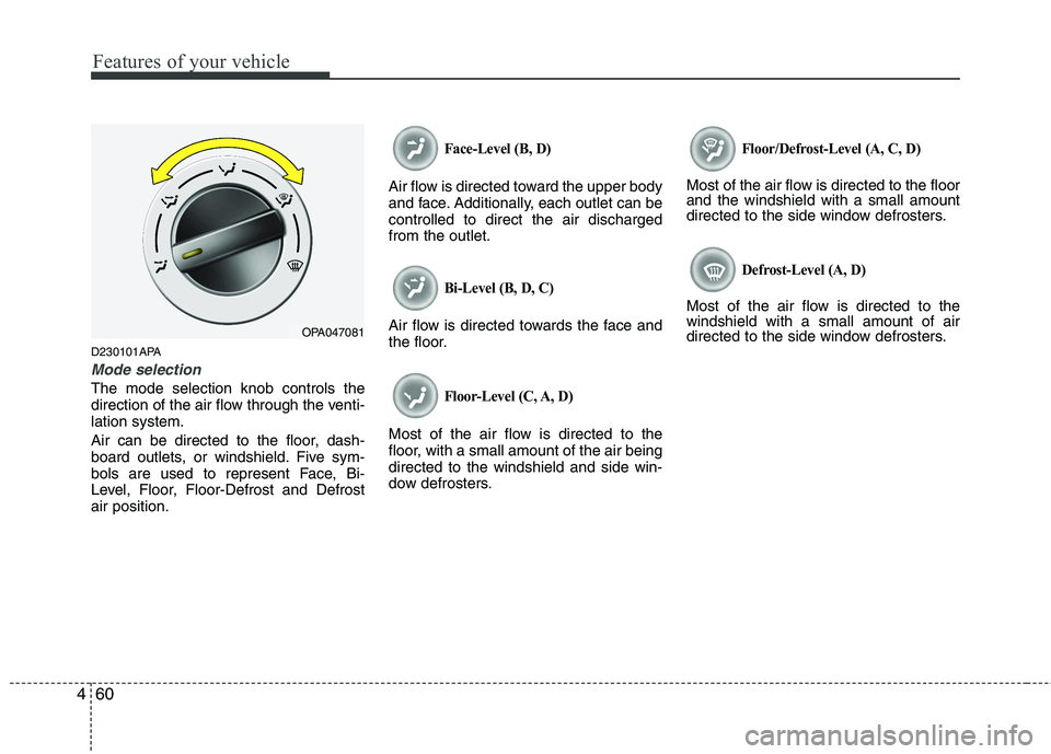
Mode selection
The mode selection knob controls the
direction of the air flow through the venti-lation system.
Air can be directed to the floor, dash-
board outlets, or windshield. Five sym-
bols are used to represent Face, Bi-
Level, Floor, Floor-Defrost and Defrostair position.
Face-Level (B, D)
Air flow is directed toward the upper body
and face. Additionally, each outlet can becontrolled to direct the air dischargedfrom the outlet.
Bi-Level (B, D, C)
Air flow is directed towards the face and
the floor.
Floor-Level (C, A, D)
Most of the air flow is directed to the
floor, with a small amount of the air beingdirected to the windshield and side win-
dow defrosters.
Floor/Defrost-Level (A, C, D)
Most of the air flow is directed to the floor and the windshield with a small amount
directed to the side window defrosters.
Defrost-Level (A, D)
Most of the air flow is directed to thewindshield with a small amount of air
directed to the side window defrosters.
OPA047081
Page 140 of 354
461
Features of your vehicle
Instrument panel vents
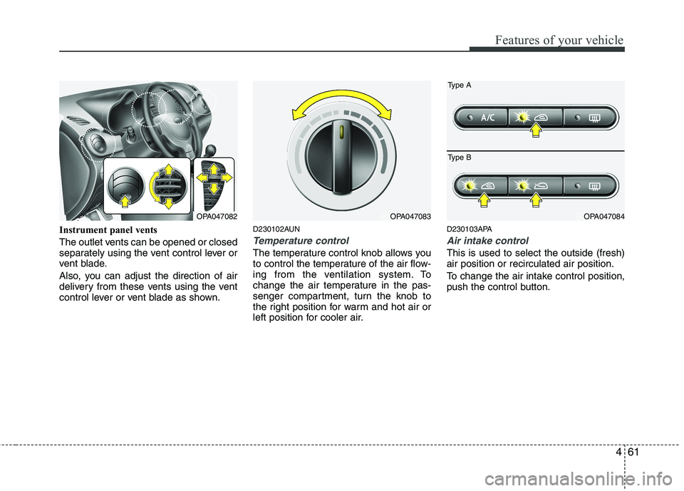
The outlet vents can be opened or closed
separately using the vent control lever or
vent blade.
Also, you can adjust the direction of air
delivery from these vents using the vent
control lever or vent blade as shown.D230102AUN
Temperature control
The temperature control knob allows you
to control the temperature of the air flow-
ing from the ventilation system. To
change the air temperature in the pas-
senger compartment, turn the knob to
the right position for warm and hot air or
left position for cooler air.D230103APA
Air intake control
This is used to select the outside (fresh) air position or recirculated air position.
To change the air intake control position,
push the control button.
OPA047083OPA047084OPA047082
Type A
Type B