turn signal HYUNDAI I10 2013 User Guide
[x] Cancel search | Manufacturer: HYUNDAI, Model Year: 2013, Model line: I10, Model: HYUNDAI I10 2013Pages: 343, PDF Size: 9.14 MB
Page 149 of 343
Features of your vehicle
88 4
✽NOTICE
• If you install an aftermarket HID
head lamp, your vehicle’s audio and
electronic device may malfunction.
• Prevent chemicals such as perfume,
cosmetic oil, sun cream, hand cleaner
and air freshener from contacting the
interior parts because they may cause
damage or discoloration.
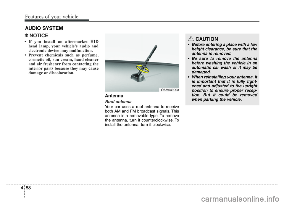
Antenna
Roof antenna
Your car uses a roof antenna to receive
both AM and FM broadcast signals. This
antenna is a removable type. To remove
the antenna, turn it counterclockwise. To
install the antenna, turn it clockwise.
AUDIO SYSTEM
CAUTION
• Before entering a place with a low
height clearance, be sure that the
antenna is removed.
• Be sure to remove the antenna
before washing the vehicle in an
automatic car wash or it may be
damaged.
• When reinstalling your antenna, it
is important that it is fully tight-
ened and adjusted to the upright
position to ensure proper recep-
tion. But it could be removed
when parking the vehicle.
OAM049093
Page 192 of 343
✽NOTICE - USING THE
Bluetooth®Wireless Technology
CELLULAR PHONE
• Do not use a cellular phone or perform
Bluetooth®Wireless Technology set-
tings (e.g. pairing a phone) while driv-
ing.
• Some Bluetooth
®Wireless Technology -
enabled phones may not be recognized
by the system or fully compatible with
the system.
• Before using Bluetooth
®Wireless
Technology related features of the
audio system, refer your phone’s User’s
Manual for phone-side Bluetooth
®
Wireless Technology operations.
• The phone must be paired to the audio
system to use Bluetooth
®Wireless
Technology related features.
• You will not be able to use the hands-
free feature when your phone (in the
car) is outside of the cellular service
area (e.g. in a tunnel, in a underground,
in a mountainous area, etc.).
(Continued)(Continued)
• If the cellular phone signal is poor or
the vehicles interior noise is too loud, it
may be difficult to hear the other per-
son’s voice during a call.
• Do not place the phone near or inside
metallic objects, otherwise communica-
tions with Bluetooth
®Wireless
Technology system or cellular service
stations can be disturbed.
• While a phone is connected through
Bluetooth
®Wireless Technology your
phone may discharge quicker than
usual for additional Bluetooth
®
Wireless Technology-related opera-
tions.
• Some cellular phones or other devices
may cause interference noise or mal-
function to audio system. In this case,
store the device in a different location
may resolve the condition.
• Phone contact names should be saved
in English or they may not be displayed
correctly.
(Continued)(Continued)
• If Priority is set upon vehicle
ignition(IGN/ACC ON), the Bluetooth
®
Wireless Technology phone will be
automatically connected.
Even if you are outside, the Bluetooth
®
Wireless Technology phone will be
automatically connected once you are
in the vicinity of the vehicle.
If you do not want automatic
Bluetooth
®Wireless Technology con-
nection, turn the Bluetooth®Wireless
Technology feature off.
• The hands-free call volume and quality
may differ depending on the mobile
phone type.
•Bluetooth
®Wireless Technology fea-
tures can be used only when the mobile
phone has been paired and connected
with the device. For more information
on pairing and connecting Bluetooth
®
Wireless Technology enabled mobile
phones, refer to the “Phone Setup” sec-
tion.
(Continued)
Features of your vehicle
131 4
Page 224 of 343
531
Driving your vehicle
Emergency Stop Signal (ESS)
(if equipped)
The Emergency Stop Signal system
alerts the driver behind by blinking the
stop light when the vehicle brakes rapid-
ly and severely.
The system is activated when:
• The vehicle suddenly stops (vehicle
speed is over 55km/h (34mph) and the
vehicle deceleration is greater than
7m/s2).
• The ABS is activating.
When vehicle speed is under 40 km/h
(25mph) and the ABS deactivates or
the sudden stop situation is over, the
stop light will stop blinking. Instead, the
hazard warning flasher will turn on
automatically. The hazard warning
flasher will turn off when vehicle speed
is over 10km/h (6mph) after the vehicle
has stopped. Also, it will turn off when
the vehicle is driven at low speed for
some time. You can turn it off manually
by pressing the hazard warning flasher
switch.
Good braking practices Wet brakes can be dangerous! The
brakes may get wet if the vehicle is driv-
en through standing water or if it is
washed. Your vehicle will not stop as
quickly if the brakes are wet. Wet brakes
may cause the vehicle to pull to one side.
To dry the brakes, apply the brakes light-
ly until the braking action returns to nor-
mal, taking care to keep the vehicle
under control at all times. If the braking
action does not return to normal, stop as
soon as it is safe to do so and we rec-
ommend that you call an authorized
HYUNDAI dealer for assistance.
DO NOT drive with your foot resting on
the brake pedal. Even light, but constant
pedal pressure can result in the brakes
overheating, brake wear, and possibly
even brake failure.
If a tire goes flat while you are driving,
apply the brakes gently and keep the
vehicle pointed straight ahead while you
slow down. When you are moving slowly
enough for it to be safe to do so, pull off
the road and stop in a safe location.
Keep your foot firmly on the brake pedal
when the vehicle is stopped to prevent
the vehicle from rolling forward.
WARNING
Whenever leaving the vehicle or
parking, always come to a complete
stop and continue to depress the
brake pedal. Move the shift lever
into the 1st gear (for manual
transaxle vehicle) or P (Park, for
automatic transaxle vehicle) posi-
tion, then apply the parking brake,
and place the ignition switch in the
LOCK/OFF position.
Vehicles with the parking brake not
fully engaged are at risk for moving
inadvertently and causing injury to
yourself or others.
Page 235 of 343
What to do in an emergency
2 6
ROAD WARNING
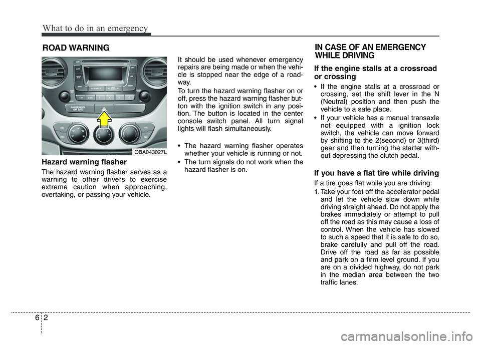
Hazard warning flasher
The hazard warning flasher serves as a
warning to other drivers to exercise
extreme caution when approaching,
overtaking, or passing your vehicle.It should be used whenever emergency
repairs are being made or when the vehi-
cle is stopped near the edge of a road-
way.
To turn the hazard warning flasher on or
off, press the hazard warning flasher but-
ton with the ignition switch in any posi-
tion. The button is located in the center
console switch panel. All turn signal
lights will flash simultaneously.
• The hazard warning flasher operates
whether your vehicle is running or not.
• The turn signals do not work when the
hazard flasher is on.
If the engine stalls at a crossroad
or crossing
• If the engine stalls at a crossroad or
crossing, set the shift lever in the N
(Neutral) position and then push the
vehicle to a safe place.
• If your vehicle has a manual transaxle
not equipped with a ignition lock
switch, the vehicle can move forward
by shifting to the 2(second) or 3(third)
gear and then turning the starter with-
out depressing the clutch pedal.
If you have a flat tire while driving
If a tire goes flat while you are driving:
1. Take your foot off the accelerator pedal
and let the vehicle slow down while
driving straight ahead. Do not apply the
brakes immediately or attempt to pull
off the road as this may cause a loss of
control. When the vehicle has slowed
to such a speed that it is safe to do so,
brake carefully and pull off the road.
Drive off the road as far as possible
and park on a firm level ground. If you
are on a divided highway, do not park
in the median area between the two
traffic lanes.
IN CASE OF AN EMERGENCY
WHILE DRIVING
OBA043027L
Page 254 of 343
• Tire sidewall labeling . . . . . . . . . . . . . . . . . . . . . . . . . 7-47
• Low aspect ratio tire . . . . . . . . . . . . . . . . . . . . . . . . . . 7-51
FUSES . . . . . . . . . . . . . . . . . . . . . . . . . . . . . . . . . . . 7-52
• Instrument panel fuse replacement . . . . . . . . . . . . . . 7-53
• Engine compartment panel fuse replacement . . . . . 7-55
• Main fuse (multi fuse) . . . . . . . . . . . . . . . . . . . . . . . . . 7-56
• Fuse/relay panel description. . . . . . . . . . . . . . . . . . . . 7-57
LIGHT BULBS. . . . . . . . . . . . . . . . . . . . . . . . . . . . 7-69
• Headlight, position light, turn signal light, and
front fog light bulb replacement . . . . . . . . . . . . . . . 7-70
• Side repeater light bulb replacement . . . . . . . . . . . . 7-72
• Rear combination light bulb replacement . . . . . . . . 7-72
• Rear fog light bulb replacement . . . . . . . . . . . . . . . . 7-74
• High mounted stop light . . . . . . . . . . . . . . . . . . . . . . . 7-74
• License plate light bulb replacement . . . . . . . . . . . . 7-74
• Interior light bulb replacement . . . . . . . . . . . . . . . . . 7-75
APPEARANCE CARE . . . . . . . . . . . . . . . . . . . . . 7-76
• Exterior care . . . . . . . . . . . . . . . . . . . . . . . . . . . . . . . . 7-76
• Interior care . . . . . . . . . . . . . . . . . . . . . . . . . . . . . . . . . 7-81
EMISSION CONTROL SYSTEM . . . . . . . . . . . . 7-82
• Crankcase emission control system . . . . . . . . . . . . . . 7-82
• Evaporative emission control system. . . . . . . . . . . . . 7-82
• Exhaust emission control system . . . . . . . . . . . . . . . . 7-83
7
Page 322 of 343
Maintenance
70 7
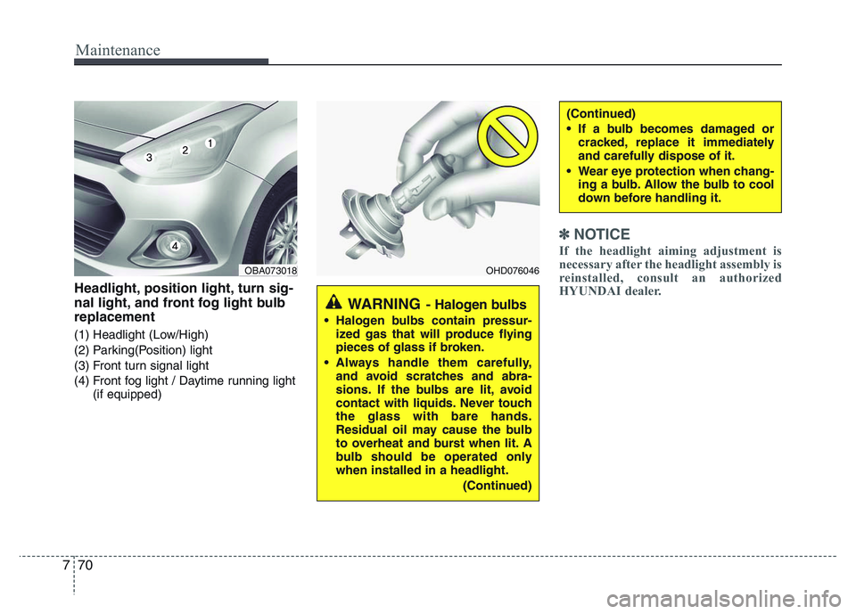
Headlight, position light, turn sig-
nal light, and front fog light bulb
replacement
(1) Headlight (Low/High)
(2) Parking(Position) light
(3) Front turn signal light
(4) Front fog light / Daytime running light
(if equipped)
✽NOTICE
If the headlight aiming adjustment is
necessary after the headlight assembly is
reinstalled, consult an authorized
HYUNDAI dealer.
OBA073018OHD076046
WARNING- Halogen bulbs
• Halogen bulbs contain pressur-
ized gas that will produce flying
pieces of glass if broken.
• Always handle them carefully,
and avoid scratches and abra-
sions. If the bulbs are lit, avoid
contact with liquids. Never touch
the glass with bare hands.
Residual oil may cause the bulb
to overheat and burst when lit. A
bulb should be operated only
when installed in a headlight.
(Continued)
(Continued)
• If a bulb becomes damaged or
cracked, replace it immediately
and carefully dispose of it.
• Wear eye protection when chang-
ing a bulb. Allow the bulb to cool
down before handling it.
Page 323 of 343
771
Maintenance
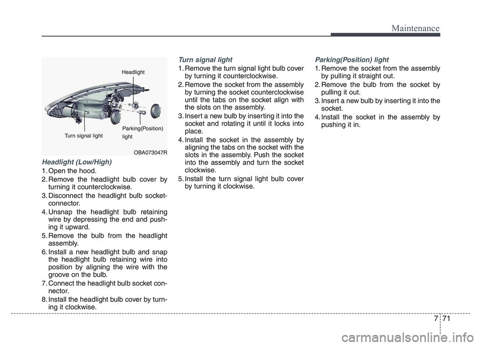
Headlight (Low/High)
1. Open the hood.
2. Remove the headlight bulb cover by
turning it counterclockwise.
3. Disconnect the headlight bulb socket-
connector.
4. Unsnap the headlight bulb retaining
wire by depressing the end and push-
ing it upward.
5. Remove the bulb from the headlight
assembly.
6. Install a new headlight bulb and snap
the headlight bulb retaining wire into
position by aligning the wire with the
groove on the bulb.
7. Connect the headlight bulb socket con-
nector.
8. Install the headlight bulb cover by turn-
ing it clockwise.
Turn signal light
1. Remove the turn signal light bulb cover
by turning it counterclockwise.
2. Remove the socket from the assembly
by turning the socket counterclockwise
until the tabs on the socket align with
the slots on the assembly.
3. Insert a new bulb by inserting it into the
socket and rotating it until it locks into
place.
4. Install the socket in the assembly by
aligning the tabs on the socket with the
slots in the assembly. Push the socket
into the assembly and turn the socket
clockwise.
5. Install the turn signal light bulb cover
by turning it clockwise.
Parking(Position) light
1. Remove the socket from the assembly
by pulling it straight out.
2. Remove the bulb from the socket by
pulling it out.
3. Insert a new bulb by inserting it into the
socket.
4. Install the socket in the assembly by
pushing it in.
OBA073047R
Headlight
Parking(Position)
light Turn signal light
Page 324 of 343
Maintenance
72 7
Front fog light bulb replacement
1. Reach your hand into the back of the
front bumper.
2. Disconnect the power connector from
the socket.
3. Remove the bulb-socket from the
housing by turning the socket counter-
clockwise until the tabs on the socket
align with the slots on the housing.
4. Install the new bulb-socket into the
housing by aligning the tabs on the
socket with the slots in the housing.
Push the socket into the housing and
turn the socket clockwise.
5. Connect the power connector to the
socket.
6. Reinstall the front bumper under cover.
Side repeater light bulb replace-
ment
If the light bulb does not operate, we rec-
ommend that the vehicle be checked by
an authorized HYUNDAI dealer.
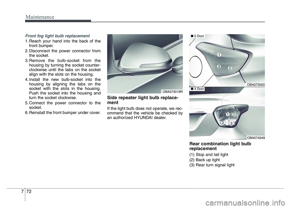
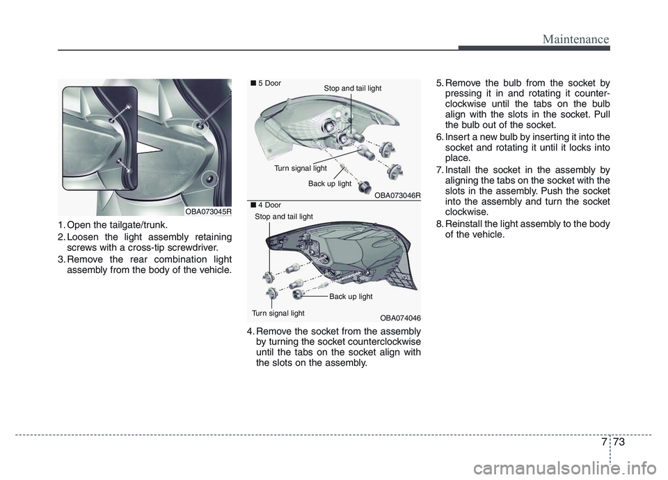
Rear combination light bulb
replacement
(1) Stop and tail light
(2) Back up light
(3) Rear turn signal light
OBA073019R
OBA073020
OBA074049
■5 Door
■4 Door
Page 325 of 343
773
Maintenance
1. Open the tailgate/trunk.
2. Loosen the light assembly retaining
screws with a cross-tip screwdriver.
3. Remove the rear combination light
assembly from the body of the vehicle.
4. Remove the socket from the assembly
by turning the socket counterclockwise
until the tabs on the socket align with
the slots on the assembly.5. Remove the bulb from the socket by
pressing it in and rotating it counter-
clockwise until the tabs on the bulb
align with the slots in the socket. Pull
the bulb out of the socket.
6. Insert a new bulb by inserting it into the
socket and rotating it until it locks into
place.
7. Install the socket in the assembly by
aligning the tabs on the socket with the
slots in the assembly. Push the socket
into the assembly and turn the socket
clockwise.
8. Reinstall the light assembly to the body
of the vehicle.
OBA073045R
OBA073046R
OBA074046 ■5 Door
■4 Door
Back up light
Turn signal light
Stop and tail light
Turn signal lightBack up light
Stop and tail light
Page 338 of 343
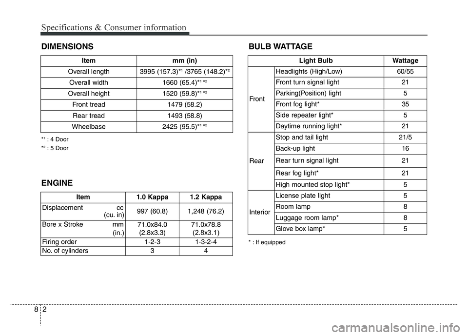
BULB WATTAGE
Specifications & Consumer information
2 8
DIMENSIONS
* : If equipped *
1: 4 Door
*2: 5 Door
Light Bulb Wattage
FrontHeadlights (High/Low) 60/55
Front turn signal light 21
Parking(Position) light 5
Front fog light* 35
Side repeater light* 5
Daytime running light* 21
RearStop and tail light 21/5
Back-up light 16
Rear turn signal light 21
Rear fog light* 21
High mounted stop light* 5
InteriorLicense plate light 5
Room lamp 8
Luggage room lamp* 8
Glove box lamp* 5
ENGINE
Item 1.0 Kappa 1.2 Kappa
Displacement cc
(cu. in) 997 (60.8) 1,248 (76.2)
Bore x Stroke mm
(in.)71.0x84.0
(2.8x3.3)71.0x78.8
(2.8x3.1)
Firing order 1-2-3 1-3-2-4
No. of cylinders 3 4
Item mm (in)
Overall length 3995 (157.3)*
1/3765 (148.2)*2
Overall width 1660 (65.4)*1 *2
Overall height 1520 (59.8)*1 *2
Front tread 1479 (58.2)
Rear tread 1493 (58.8)
Wheelbase 2425 (95.5)*
1 *2