HYUNDAI I10 2013 Owners Manual
Manufacturer: HYUNDAI, Model Year: 2013, Model line: I10, Model: HYUNDAI I10 2013Pages: 343, PDF Size: 9.14 MB
Page 301 of 343
749
Maintenance
4. Tire ply composition and material
The number of layers or plies of rub-
ber-coated fabric are in the tire. Tire
manufacturers also must indicate the
materials in the tire, which include
steel, nylon, polyester, and others.
The letter "R" means radial ply con-
struction; the letter "D" means diago-
nal or bias ply construction; and the
letter "B" means belted-bias ply con-
struction.
5. Maximum permissible inflation
pressure
This number is the greatest amount
of air pressure that should be put in
the tire. Do not exceed the maximum
permissible inflation pressure. Refer
to the Tire and Loading Information
label for recommended inflation
pressure.
6. Maximum load rating
This number indicates the maximum
load in kilograms and pounds that
can be carried by the tire. When
replacing the tires on the vehicle,
always use a tire that has the same
load rating as the factory installed
tire.
7. Uniform tire quality grading
Quality grades can be found where
applicable on the tire sidewall
between tread shoulder and maxi-
mum section width.
For example:
TREADWEAR 200
TRACTION AA
TEMPERATURE A
Tread wear
The tread wear grade is a compara-
tive rating based on the wear rate of
the tire when tested under controlled
conditions on a specified govern-
ment test course. For example, a tire
graded 150 would wear one-and-a-
half times (1½) as well on the gov-
ernment course as a tire graded 100.
The relative performance of tires
depends upon the actual conditions
of their use, however, and may
depart significantly from the norm
due to variations in driving habits,
service practices and differences in
road characteristics and climate.
WARNING - Tire age
Tires degrade over time, even
when they are not being used.
Regardless of the remaining
tread, we recommend that tires
generally be replaced after six
(6) years of normal service.
Heat caused by not climates or
frequent high loading condi-
tions can accelerate the aging
process. Failure to follow this
Warning can result in sudden
tire failure, which could lead to
a loss of control and an acci-
dent involving serious injury or
death.
Page 302 of 343
Maintenance
50 7
These grades are molded on the
side-walls of passenger vehicle tires.
The tires available as standard or
optional equipment on your vehicles
may vary with respect to grade.
Traction - AA, A, B & C
The traction grades, from highest to
lowest, are AA, A, B and C. Those
grades represent the tires ability to
stop on wet pavement as measured
under controlled conditions on spec-
ified government test surfaces of
asphalt and concrete. A tire marked
C may have poor traction perform-
ance.
Temperature -A, B & C
The temperature grades are A (the
highest), B and C representing the
tire’s resistance to the generation of
heat and its ability to dissipate heat
when tested under controlled condi-
tions on a specified indoor laboratory
test wheel.
Sustained high temperature can
cause the material of the tire to
degenerate and reduce tire life, and
excessive temperature can lead to
sudden tire failure. Grades B and A
represent higher levels of perform-
ance on the laboratory test wheel
than the minimum required by law.
WARNING
The traction grade assigned to
this tire is based on straight-
ahead braking traction tests,
and does not include accelera-
tion, cornering, hydroplaning,
or peak traction characteristics.
WARNING - Tire
temperature
The temperature grade for this
tire is established for a tire that
is properly inflated and not
overloaded. Excessive speed,
underinflation, or excessive
loading, either separately or in
combination, can cause heat
build-up and possible sudden
tire failure. This can cause loss
of vehicle control and serious
injury or death.
Page 303 of 343
751
Maintenance
Low aspect ratio tire (if equipped)
Low aspect ratio tires, the aspect
ratio is lower than 50, are provided
for sporty looks.
Because the low aspect ratio tires
are optimized for handling and brak-
ing, it may be more uncomfortable to
ride in and there is more noise com-
pare with normal tires.CAUTION
Because the sidewall of the low
aspect ratio tire is shorter than
the normal, the wheel and tire of
the low aspect ratio tire is easi-
er to be damaged. So, follow the
instructions below.
- When driving on a rough road
or off road, drive cautiously
because tires and wheels may
be damaged. And after driving,
inspect tires and wheels.
- When passing over a pothole,
speed bump, manhole, or curb
stone, drive slowly so that the
tires and wheels are not dam-
aged.
- If the tire is impacted, we rec-
ommend that you inspect the
tire condition or contact an
authorized HYUNDAI dealer.
- To prevent damage to the tire,
inspect the tire condition and
pressure every 3,000km.
CAUTION
• It is not easy to recognize the
tire damage with your own
eyes. But if there is the slight-
est hint of tire damage, even
though you cannot see the tire
damage with your own eyes,
have the tire checked or
replaced because the tire
damage may cause air leak-
age from the tire.
• If the tire is damaged by driv-
ing on a rough road, off road,
pothole, manhole, or curb
stone, it will not be covered by
the warranty.
• You can find out the tire infor-
mation on the tire sidewall.
Page 304 of 343
Maintenance
52 7
FUSES
A vehicle’s electrical system is protected
from electrical overload damage by
fuses.
This vehicle has 2 fuse panels, one locat-
ed in the driver’s side panel bolster, the
other in the engine compartment near
the battery.
If any of your vehicle’s lights, acces-
sories, or controls do not work, check the
appropriate circuit fuse. If a fuse has
blown, the element inside the fuse will
melt.
If the electrical system does not work,
first check the driver’s side fuse panel.
Always replace a blown fuse with one of
the same rating.
If the replacement fuse blows, this indi-
cates an electrical problem. Avoid using
the system involved and we recommend
that you consult an authorized HYUNDAI
dealer.
✽NOTICE
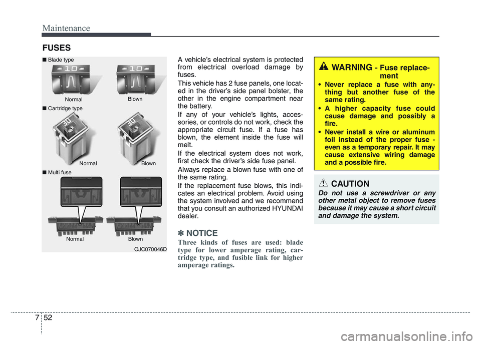
Three kinds of fuses are used: blade
type for lower amperage rating, car-
tridge type, and fusible link for higher
amperage ratings.OJC070046D Normal Normal ■Blade type
■Cartridge type
■Multi fuseBlown
Blown
Normal Blown
WARNING - Fuse replace-
ment
• Never replace a fuse with any-
thing but another fuse of the
same rating.
• A higher capacity fuse could
cause damage and possibly a
fire.
• Never install a wire or aluminum
foil instead of the proper fuse -
even as a temporary repair. It may
cause extensive wiring damage
and a possible fire.
CAUTION
Do not use a screwdriver or any
other metal object to remove fuses
because it may cause a short circuit
and damage the system.
Page 305 of 343
753
Maintenance
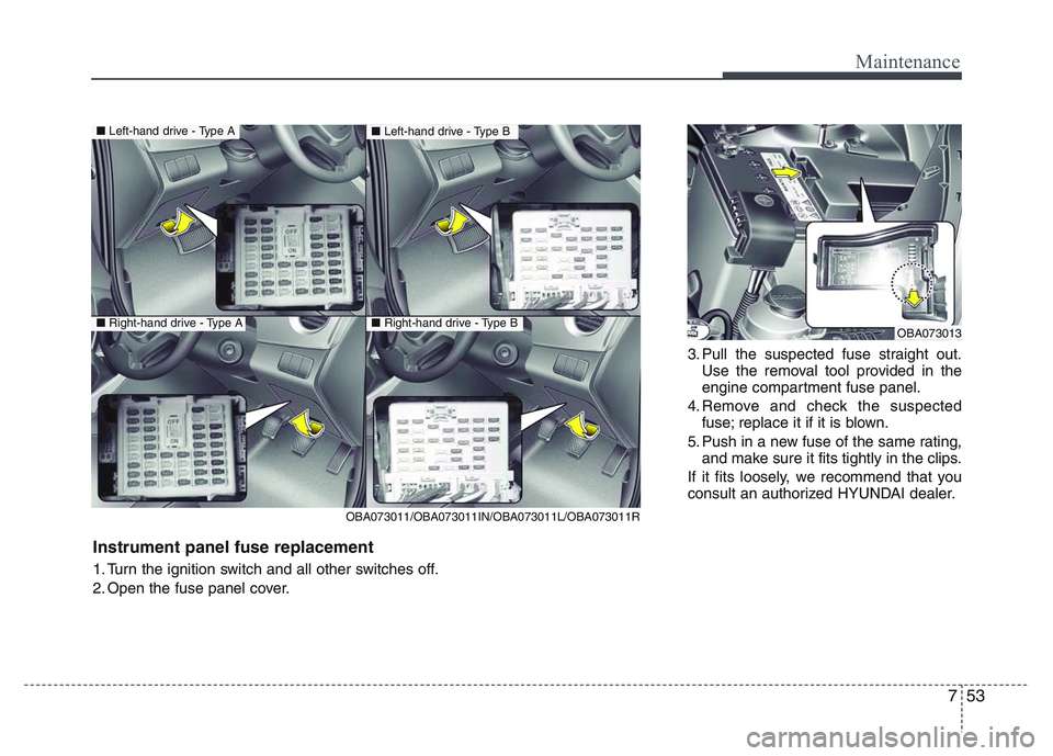
3. Pull the suspected fuse straight out.
Use the removal tool provided in the
engine compartment fuse panel.
4. Remove and check the suspected
fuse; replace it if it is blown.
5. Push in a new fuse of the same rating,
and make sure it fits tightly in the clips.
If it fits loosely, we recommend that you
consult an authorized HYUNDAI dealer.
OBA073013
■Left-hand drive - Type A
■Right-hand drive - Type A
■Left-hand drive - Type B
■Right-hand drive - Type B
OBA073011/OBA073011IN/OBA073011L/OBA073011R
Instrument panel fuse replacement
1. Turn the ignition switch and all other switches off.
2. Open the fuse panel cover.
Page 306 of 343
Maintenance
54 7
In an emergency, if you do not have a
spare, use a fuse of the same rating from
a circuit you may not need for operating
the vehicle, such as the cigarette lighter
fuse.
If the headlights or other electrical com-
ponents do not work and the fuses are
OK, check the fuse block in the engine
compartment. If a fuse is blown, it must
be replaced.
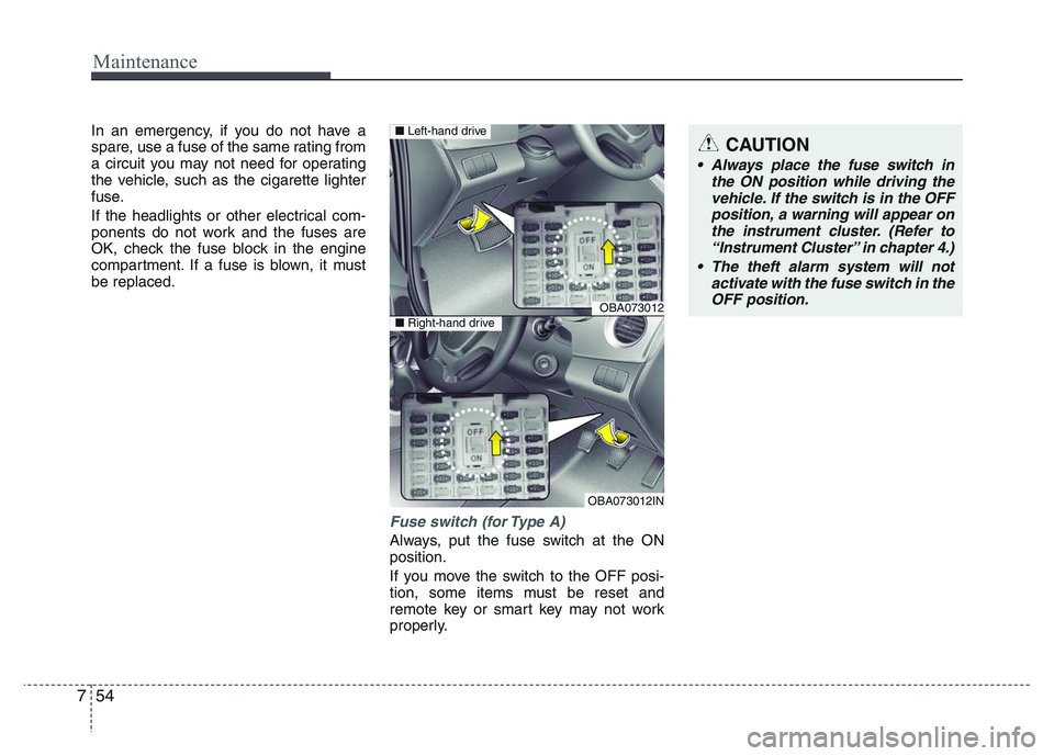
Fuse switch (for Type A)
Always, put the fuse switch at the ON
position.
If you move the switch to the OFF posi-
tion, some items must be reset and
remote key or smart key may not work
properly.
CAUTION
• Always place the fuse switch in
the ON position while driving the
vehicle. If the switch is in the OFF
position, a warning will appear on
the instrument cluster. (Refer to
“Instrument Cluster” in chapter 4.)
• The theft alarm system will not
activate with the fuse switch in the
OFF position.
OBA073012
OBA073012IN
■Left-hand drive
■Right-hand drive
Page 307 of 343
755
Maintenance
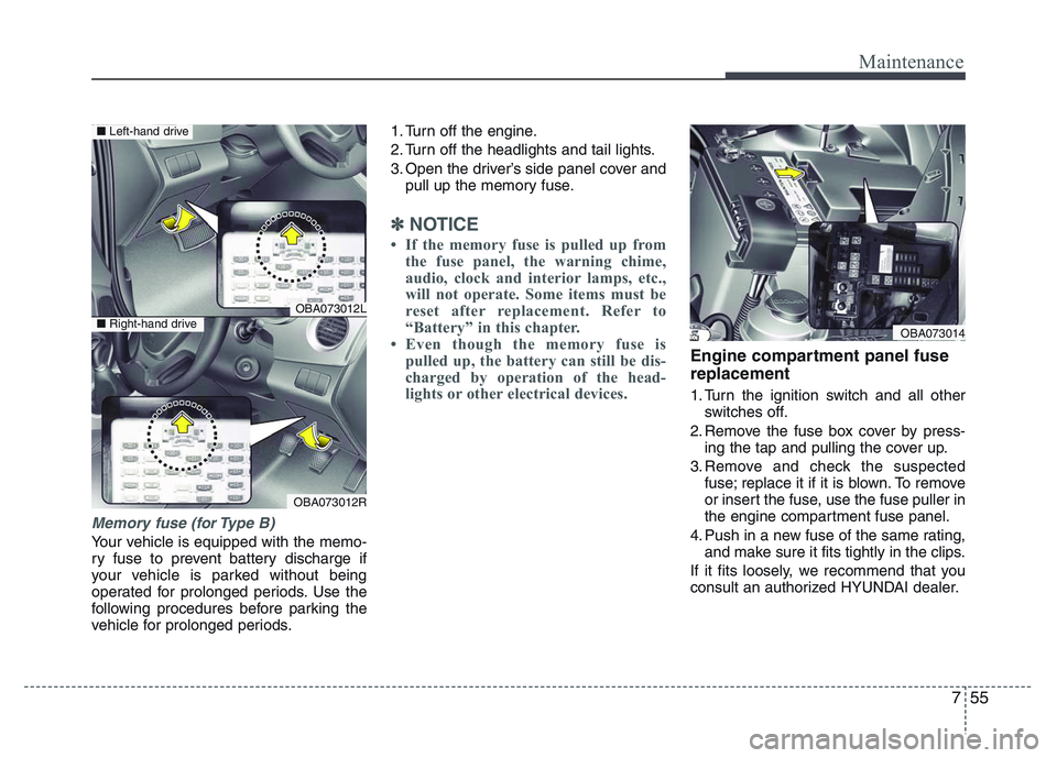
Memory fuse (for Type B)
Your vehicle is equipped with the memo-
ry fuse to prevent battery discharge if
your vehicle is parked without being
operated for prolonged periods. Use the
following procedures before parking the
vehicle for prolonged periods.1. Turn off the engine.
2. Turn off the headlights and tail lights.
3. Open the driver’s side panel cover and
pull up the memory fuse.
✽NOTICE
• If the memory fuse is pulled up from
the fuse panel, the warning chime,
audio, clock and interior lamps, etc.,
will not operate. Some items must be
reset after replacement. Refer to
“Battery” in this chapter.
• Even though the memory fuse is
pulled up, the battery can still be dis-
charged by operation of the head-
lights or other electrical devices.
Engine compartment panel fuse
replacement
1. Turn the ignition switch and all other
switches off.
2. Remove the fuse box cover by press-
ing the tap and pulling the cover up.
3. Remove and check the suspected
fuse; replace it if it is blown. To remove
or insert the fuse, use the fuse puller in
the engine compartment fuse panel.
4. Push in a new fuse of the same rating,
and make sure it fits tightly in the clips.
If it fits loosely, we recommend that you
consult an authorized HYUNDAI dealer.
OBA073012L
OBA073012R
■Left-hand drive
■Right-hand driveOBA073014
Page 308 of 343
Maintenance
56 7
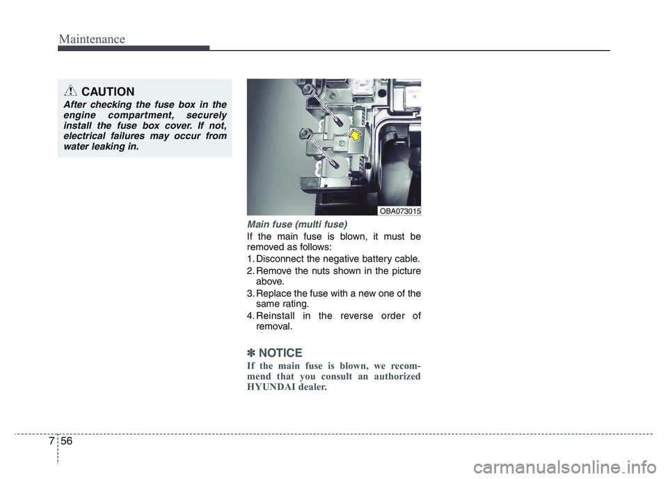
Main fuse (multi fuse)
If the main fuse is blown, it must be
removed as follows:
1. Disconnect the negative battery cable.
2. Remove the nuts shown in the picture
above.
3. Replace the fuse with a new one of the
same rating.
4. Reinstall in the reverse order of
removal.
✽NOTICE
If the main fuse is blown, we recom-
mend that you consult an authorized
HYUNDAI dealer.
CAUTION
After checking the fuse box in the
engine compartment, securely
install the fuse box cover. If not,
electrical failures may occur from
water leaking in.
OBA073015
Page 309 of 343
757
Maintenance
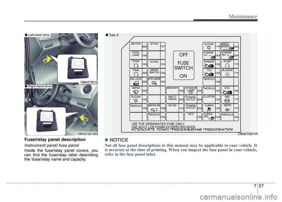
Fuse/relay panel description
Instrument panel fuse panel
Inside the fuse/relay panel covers, you
can find the fuse/relay label describing
the \fuse/relay name and capacity.
OBA073016
OBA073016INOBA073041R ■Type A
■Left-hand drive
■Right-hand drive
✽NOTICE
Not all fuse panel descriptions in this manual may be applicable to your vehicle. It
is accurate at the time of printing. When you inspect the fuse panel in your vehicle,
refer to the fuse panel label.
Page 310 of 343
Maintenance
58 7
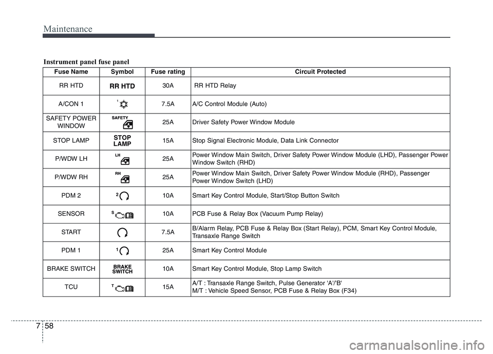
Fuse Name Symbol Fuse rating Circuit Protected
RR HTD
30A RR HTD Relay
A/CON 1
7.5A A/C Control Module (Auto)
SAFETY POWER
WINDOW
25A Driver Safety Power Window Module
STOP LAMP
STOP
LAMP15A Stop Signal Electronic Module, Data Link Connector
P/WDW LH
25APower Window Main Switch, Driver Safety Power Window Module (LHD), Passenger Power
Window Switch (RHD)
P/WDW RH
25APower Window Main Switch, Driver Safety Power Window Module (RHD), Passenger
Power Window Switch (LHD)
PDM 2
210A Smart Key Control Module, Start/Stop Button Switch
SENSOR
S10A PCB Fuse & Relay Box (Vacuum Pump Relay)
START
7.5AB/Alarm Relay, PCB Fuse & Relay Box (Start Relay), PCM, Smart Key Control Module,
Transaxle Range Switch
PDM 1
125A Smart Key Control Module
BRAKE SWITCH
10A Smart Key Control Module, Stop Lamp Switch
TCU
T15AA/T : Transaxle Range Switch, Pulse Generator 'A'/'B'
M/T : Vehicle Speed Sensor, PCB Fuse & Relay Box (F34)
Instrument panel fuse panel