ABS HYUNDAI I10 2017 User Guide
[x] Cancel search | Manufacturer: HYUNDAI, Model Year: 2017, Model line: I10, Model: HYUNDAI I10 2017Pages: 343, PDF Size: 9.14 MB
Page 298 of 343
Maintenance
46 7
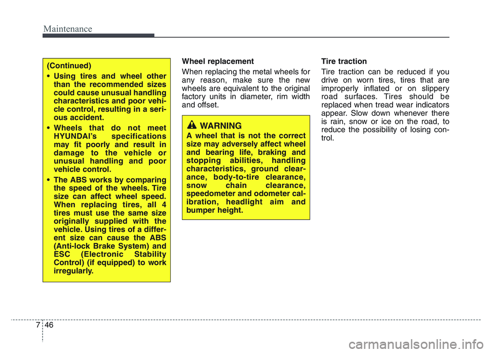
Wheel replacement
When replacing the metal wheels for
any reason, make sure the new
wheels are equivalent to the original
factory units in diameter, rim width
and offset.Tire traction
Tire traction can be reduced if you
drive on worn tires, tires that are
improperly inflated or on slippery
road surfaces. Tires should be
replaced when tread wear indicators
appear. Slow down whenever there
is rain, snow or ice on the road, to
reduce the possibility of losing con-
trol.
WARNING
A wheel that is not the correct
size may adversely affect wheel
and bearing life, braking and
stopping abilities, handling
characteristics, ground clear-
ance, body-to-tire clearance,
snow chain clearance,
speedometer and odometer cal-
ibration, headlight aim and
bumper height.
(Continued)
• Using tires and wheel other
than the recommended sizes
could cause unusual handling
characteristics and poor vehi-
cle control, resulting in a seri-
ous accident.
• Wheels that do not meet
HYUNDAI’s specifications
may fit poorly and result in
damage to the vehicle or
unusual handling and poor
vehicle control.
• The ABS works by comparing
the speed of the wheels. Tire
size can affect wheel speed.
When replacing tires, all 4
tires must use the same size
originally supplied with the
vehicle. Using tires of a differ-
ent size can cause the ABS
(Anti-lock Brake System) and
ESC (Electronic Stability
Control) (if equipped) to work
irregularly.
Page 312 of 343
Maintenance
60 7
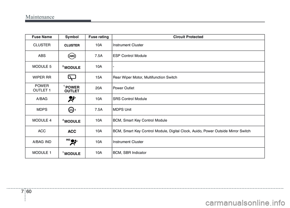
Fuse Name Symbol Fuse rating Circuit Protected
CLUSTER
10A Instrument Cluster
ABS
7.5A ESP Control Module
MODULE 5
5 MODULE10A -
WIPER RR
15A Rear Wiper Motor, Multifunction Switch
POWER
OUTLET 1
1 POWER
OUTLET20A Power Outlet
A/BAG
10A SRS Control Module
MDPS
7.5A MDPS Unit
MODULE 4
4 MODULE10A BCM, Smart Key Control Module
ACC
10A BCM, Smart Key Control Module, Digital Clock, Auido, Power Outside Mirror Switch
A/BAG IND
10A Instrument Cluster
MODULE 1
1 MODULE10A BCM, SBR Indicator
Page 315 of 343
763
Maintenance
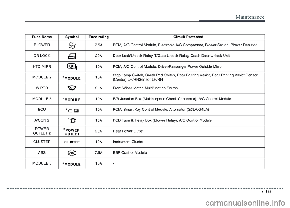
Fuse Name Symbol Fuse rating Circuit Protected
BLOWER
7.5A PCM, A/C Control Module, Electronic A/C Compressor, Blower Switch, Blower Resistor
DR LOCK
20A Door Lock/Unlock Relay, T/Gate Unlock Relay, Crash Door Unlock Unit
HTD MIRR
10A PCM, A/C Control Module, Driver/Passenger Power Outside Mirror
MODULE 2
2 MODULE10AStop Lamp Switch, Crash Pad Switch, Rear Parking Assist, Rear Parking Assist Sensor
(Center) LH/RHSensor LH/RH
WIPER
25A Front Wiper Motor, Multifunction Switch
MODULE 3
3 MODULE10A E/R Junction Box (Multipurpose Check Connector), A/C Control Module
ECU
E10A PCM, Smart Key Control Module, Alternator (G3LA/G4LA)
A/CON 2
10A PCB Fuse & Relay Box (Blower Relay), A/C Control Module
POWER
OUTLET 2
2 POWER
OUTLET20A Rear Power Outlet
CLUSTER
10A Instrument Cluster
ABS
7.5A ESP Control Module
MODULE 5
5 MODULE10A -
Page 323 of 343
771
Maintenance
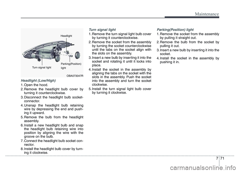
Headlight (Low/High)
1. Open the hood.
2. Remove the headlight bulb cover by
turning it counterclockwise.
3. Disconnect the headlight bulb socket-
connector.
4. Unsnap the headlight bulb retaining
wire by depressing the end and push-
ing it upward.
5. Remove the bulb from the headlight
assembly.
6. Install a new headlight bulb and snap
the headlight bulb retaining wire into
position by aligning the wire with the
groove on the bulb.
7. Connect the headlight bulb socket con-
nector.
8. Install the headlight bulb cover by turn-
ing it clockwise.
Turn signal light
1. Remove the turn signal light bulb cover
by turning it counterclockwise.
2. Remove the socket from the assembly
by turning the socket counterclockwise
until the tabs on the socket align with
the slots on the assembly.
3. Insert a new bulb by inserting it into the
socket and rotating it until it locks into
place.
4. Install the socket in the assembly by
aligning the tabs on the socket with the
slots in the assembly. Push the socket
into the assembly and turn the socket
clockwise.
5. Install the turn signal light bulb cover
by turning it clockwise.
Parking(Position) light
1. Remove the socket from the assembly
by pulling it straight out.
2. Remove the bulb from the socket by
pulling it out.
3. Insert a new bulb by inserting it into the
socket.
4. Install the socket in the assembly by
pushing it in.
OBA073047R
Headlight
Parking(Position)
light Turn signal light
Page 324 of 343
Maintenance
72 7
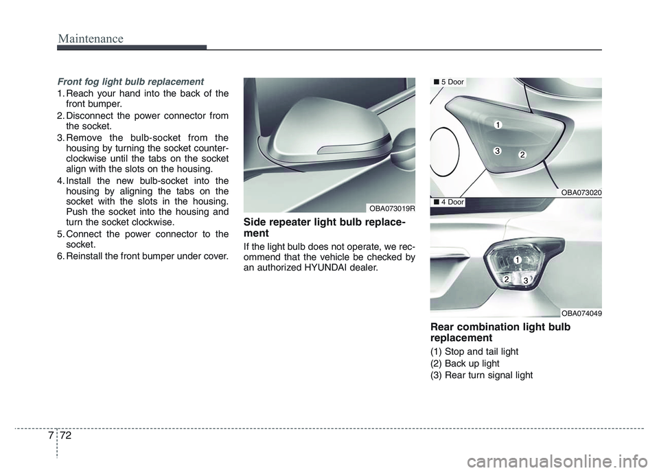
Front fog light bulb replacement
1. Reach your hand into the back of the
front bumper.
2. Disconnect the power connector from
the socket.
3. Remove the bulb-socket from the
housing by turning the socket counter-
clockwise until the tabs on the socket
align with the slots on the housing.
4. Install the new bulb-socket into the
housing by aligning the tabs on the
socket with the slots in the housing.
Push the socket into the housing and
turn the socket clockwise.
5. Connect the power connector to the
socket.
6. Reinstall the front bumper under cover.
Side repeater light bulb replace-
ment
If the light bulb does not operate, we rec-
ommend that the vehicle be checked by
an authorized HYUNDAI dealer.
Rear combination light bulb
replacement
(1) Stop and tail light
(2) Back up light
(3) Rear turn signal light
OBA073019R
OBA073020
OBA074049
■5 Door
■4 Door
Page 325 of 343
773
Maintenance
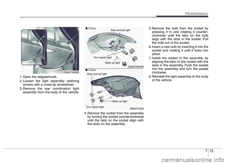
1. Open the tailgate/trunk.
2. Loosen the light assembly retaining
screws with a cross-tip screwdriver.
3. Remove the rear combination light
assembly from the body of the vehicle.
4. Remove the socket from the assembly
by turning the socket counterclockwise
until the tabs on the socket align with
the slots on the assembly.5. Remove the bulb from the socket by
pressing it in and rotating it counter-
clockwise until the tabs on the bulb
align with the slots in the socket. Pull
the bulb out of the socket.
6. Insert a new bulb by inserting it into the
socket and rotating it until it locks into
place.
7. Install the socket in the assembly by
aligning the tabs on the socket with the
slots in the assembly. Push the socket
into the assembly and turn the socket
clockwise.
8. Reinstall the light assembly to the body
of the vehicle.
OBA073045R
OBA073046R
OBA074046 ■5 Door
■4 Door
Back up light
Turn signal light
Stop and tail light
Turn signal lightBack up light
Stop and tail light
Page 326 of 343
Maintenance
74 7
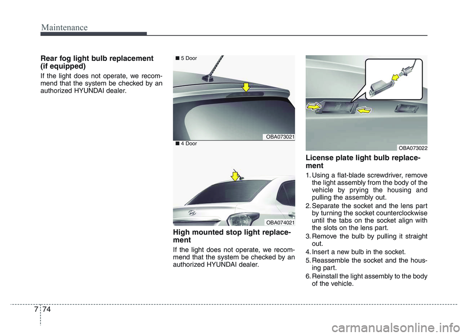
Rear fog light bulb replacement
(if equipped)
If the light does not operate, we recom-
mend that the system be checked by an
authorized HYUNDAI dealer.
High mounted stop light replace-
ment
If the light does not operate, we recom-
mend that the system be checked by an
authorized HYUNDAI dealer.
License plate light bulb replace-
ment
1. Using a flat-blade screwdriver, remove
the light assembly from the body of the
vehicle by prying the housing and
pulling the assembly out.
2. Separate the socket and the lens part
by turning the socket counterclockwise
until the tabs on the socket align with
the slots on the lens part.
3. Remove the bulb by pulling it straight
out.
4. Insert a new bulb in the socket.
5. Reassemble the socket and the hous-
ing part.
6. Reinstall the light assembly to the body
of the vehicle.
OBA073022
OBA073021
OBA074021
■5 Door
■4 Door
Page 327 of 343
775
Maintenance
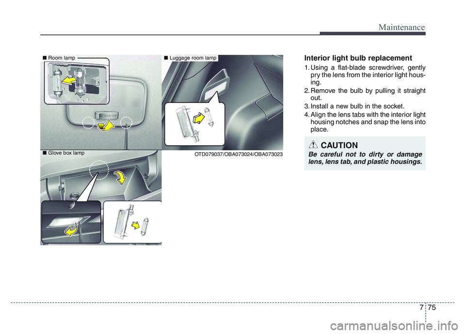
Interior light bulb replacement
1. Using a flat-blade screwdriver, gently
pry the lens from the interior light hous-
ing.
2. Remove the bulb by pulling it straight
out.
3. Install a new bulb in the socket.
4. Align the lens tabs with the interior light
housing notches and snap the lens into
place.
CAUTION
Be careful not to dirty or damage
lens, lens tab, and plastic housings.
■Room lamp
■Glove box lamp ■Luggage room lamp
OTD079037/OBA073024/OBA073023
Page 334 of 343
Maintenance
82 7
EMISSION CONTROL SYSTEM
The emission control system of your
vehicle is covered by a written limited
warranty. Please see the warranty infor-
mation contained in the Service Passport
in your vehicle.
Your vehicle is equipped with an emis-
sion control system to meet all emission
regulations.
There are three emission control sys-
tems which are as follows.
(1) Crankcase emission control system
(2) Evaporative emission control system
(3) Exhaust emission control system
In order to assure the proper function of
the emission control systems, it is rec-
ommended that you have your vehicle
inspected and maintained by an author-
ized HYUNDAI dealer in accordance with
the maintenance schedule in this manu-
al.Caution for the Inspection and
Maintenance Test (With Electronic
Stability Control (ESC) system)
• To prevent the vehicle from misfir-
ing during dynamometer testing,
turn the Electronic Stability Control
(ESC) system off by pressing the
ESC switch.
• After dynamometer testing is com-
pleted, turn the ESC system back on
by pressing the ESC switch again.
1. Crankcase emission control
system
The positive crankcase ventilation sys-
tem is employed to prevent air pollution
caused by blow-by gases being emitted
from the crankcase. This system supplies
fresh filtered air to the crankcase through
the air intake hose. Inside the crankcase,
the fresh air mixes with blow-by gases,
which then pass through the PCV valve
into the induction system.
2. Evaporative emission control
System
The Evaporative Emission Control
System is designed to prevent fuel
vapors from escaping into the atmos-
phere.
Canister
Fuel vapors generated inside the fuel
tank are absorbed and stored in the
onboard canister. When the engine is
running, the fuel vapors absorbed in the
canister are drawn into the surge tank
through the purge control solenoid valve.
Purge Control Solenoid Valve (PCSV)
The purge control solenoid valve is con-
trolled by the Engine Control Module
(ECM); when the engine coolant temper-
ature is low during idling, the PCSV clos-
es so that evaporated fuel is not taken
into the engine. After the engine warms
up during ordinary driving, the PCSV
opens to introduce evaporated fuel to the
engine.