check engine HYUNDAI I30 2011 Workshop Manual
[x] Cancel search | Manufacturer: HYUNDAI, Model Year: 2011, Model line: I30, Model: HYUNDAI I30 2011Pages: 635, PDF Size: 40.66 MB
Page 347 of 635
Maintenance
30
7
✽✽
NOTICE
“C” (COLD) range is for reference only
and should NOT be used to determine
transaxle fluid level. ✽
✽
NOTICE
New automatic transaxle fluid should be
red. The red dye is added so the assem-
bly plant can identify it as automatic
transaxle fluid and distinguish it from
engine oil or antifreeze. The red dye,
which is not an indicator of fluid quali-
ty, is not permanent. As the vehicle is
driven, the automatic transaxle fluid
will begin to look darker. The color may
eventually appear light brown.
Therefore, have an authorized
HYUNDAI dealer change the automatic
transaxle fluid according to the
Scheduled Maintenance at the begin-
ning of this section.
Use only the specified automatic
transaxle fluid. (Refer to “Recommended
lubricants and capacities” in section 9.) G100200AFD Changing the automatic transaxle fluid
Have automatic transaxle fluid changed
by an authorized HYUNDAI dealeraccording to the Maintenance Scheduleat the beginning of this section.
WARNING - Transaxle fluid
The transaxle fluid level should be
checked when the engine is at nor-
mal operating temperature. This
means that the engine, radiator,
radiator hose and exhaust system
etc., are very hot. Exercise great
care not to burn yourself during
this procedure.
WARNING - Parking brake
To avoid sudden movement of the
vehicle, apply parking brake and
depress the brake pedal before
moving the shift lever.
CAUTION
Low fluid level causes transaxle slippage. Overfilling can cause
foaming, loss of fluid and transaxlemalfunction.
The use of a non-specified fluid could result in transaxle malfunc-
tion and failure.
Page 349 of 635
Maintenance
32
7
FUEL FILTER (FOR DIESEL)
G150100AFD
Draining water from fuel filter
The fuel filter for diesel engine plays an
important role of separating water from
fuel and accumulating the water in itsbottom.
If water accumulates in the fuel filter, the
warning light comes on when the ignition
switch is in the ON position.
If the light is turned on, take your car to
the authorised HYUNDAI dealer and
have drain the water and checked thesystem. G150200AFD
Fuel filter cartridge replacement
✽✽NOTICE
When replacing the fuel filter cartridge,
use HYUNDAI genuine parts.
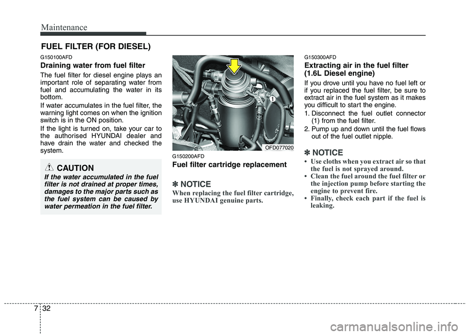
G150300AFD Extracting air in the fuel filter (1.6L Diesel engine)
If you drove until you have no fuel left or
if you replaced the fuel filter, be sure to
extract air in the fuel system as it makes
you difficult to start the engine.
1. Disconnect the fuel outlet connector (1) from the fuel filter.
2. Pump up and down until the fuel flows out of the fuel outlet nipple.
✽✽ NOTICE
Use cloths when you extract air so that the fuel is not sprayed around.
Clean the fuel around the fuel filter or the injection pump before starting the
engine to prevent fire.
Finally, check each part if the fuel is
leaking. OFD077020
CAUTION
If the water accumulated in the fuel
filter is not drained at proper times,damages to the major parts such as
the fuel system can be caused by water permeation in the fuel filter.
Page 359 of 635
Maintenance
42
7
G130300AUN Reset items
Items should be reset after the battery
has been discharged or the battery hasbeen disconnected.
Auto up/down window (See section 4)
Sunroof (See section 4)
Trip computer (See section 4)
Climate control system
(See section 4)
Clock (See section 4)
Audio (See section 4)(Continued)
Before performing maintenance or recharging the battery, turn off all accessories and stop the
engine.
The negative battery cable must be removed first and installed
last when the battery is discon-nected.WARNING - Recharging
battery
When recharging the battery,
observe the following precautions:
The battery must be removed from the vehicle and placed in an area with good ventilation.
Do not allow cigarettes, sparks, or flame near the battery.
Watch the battery during charg- ing, and stop or reduce the charg-
ing rate if the battery cells begin
gassing (boiling) violently or if
the temperature of the electrolyte
of any cell exceeds 49°C (120°F).
Wear eye protection when check- ing the battery during charging.
Disconnect the battery charger in the following order.
1. Turn off the battery charger main switch.
2. Unhook the negative clamp from the negative battery terminal.
3. Unhook the positive clamp from the positive battery terminal.
(Continued)
Page 370 of 635
753
Maintenance
FUSES
G210000AFD
A vehicle’s electrical system is protected
from electrical overload damage by
fuses. This vehicle has 2 (or 3) fuse panels, one
located in the driver’s side panel bolster,
the other in the engine compartment
near the battery.
If any of your vehicle’s lights, acces-
sories, or controls do not work, check the
appropriate circuit fuse. If a fuse has
blown, the element inside the fuse will bemelted.
If the electrical system does not work,
first check the driver’s side fuse panel.
Always replace a blown fuse with one of
the same rating.
If the replacement fuse blows, this indi-
cates an electrical problem. Avoid using
the system involved and immediately
consult an authorized HYUNDAI dealer.
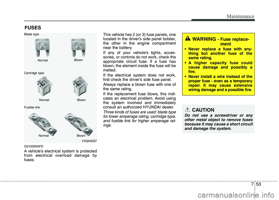
Three kinds of fuses are used: blade type
for lower amperage rating, cartridge type,
and fusible link for higher amperage rat-ings.
1VQA4037
Normal
Normal
Blade type
Cartridge type
Fusible link Blown
Blown
Normal Blown
WARNING - Fuse replace-
ment
Never replace a fuse with any- thing but another fuse of the same rating.
A higher capacity fuse could cause damage and possibly a
fire.
Never install a wire instead of the proper fuse - even as a temporary
repair. It may cause extensive
wiring damage and a possible fire.
CAUTION
Do not use a screwdriver or any
other metal object to remove fuses because it may cause a short circuitand damage the system.
Page 371 of 635
Maintenance
54
7
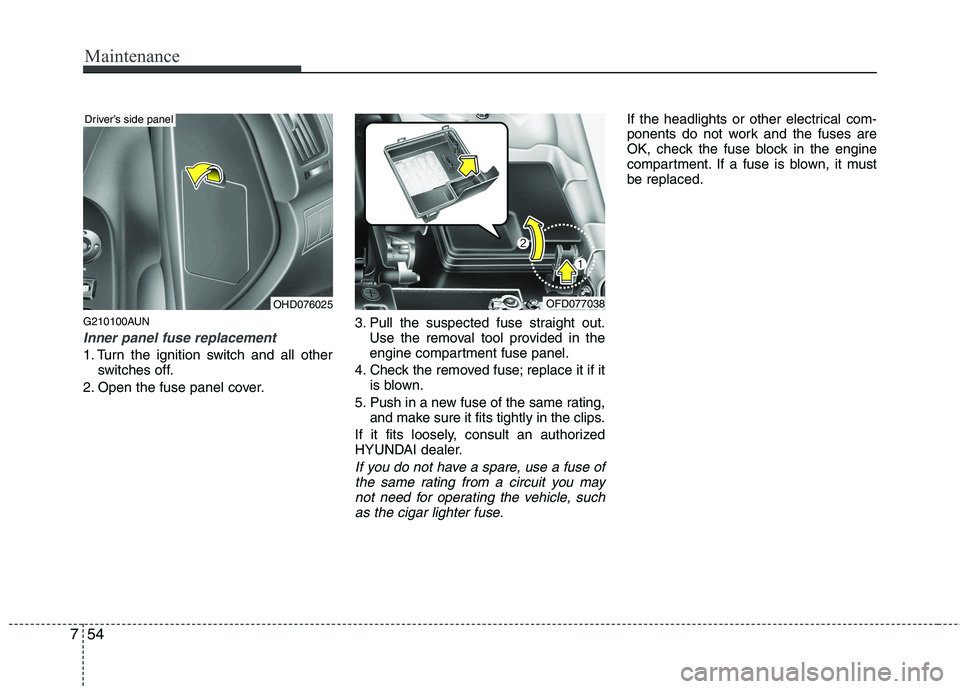
G210100AUN
Inner panel fuse replacement
1. Turn the ignition switch and all other
switches off.
2. Open the fuse panel cover. 3. Pull the suspected fuse straight out.
Use the removal tool provided in the
engine compartment fuse panel.
4. Check the removed fuse; replace it if it is blown.
5. Push in a new fuse of the same rating, and make sure it fits tightly in the clips.
If it fits loosely, consult an authorized
HYUNDAI dealer.
If you do not have a spare, use a fuse of the same rating from a circuit you may
not need for operating the vehicle, such as the cigar lighter fuse.
If the headlights or other electrical com-
ponents do not work and the fuses are
OK, check the fuse block in the engine
compartment. If a fuse is blown, it mustbe replaced.
OHD076025
Driver’s side panel
OFD077038
Page 372 of 635
755
Maintenance
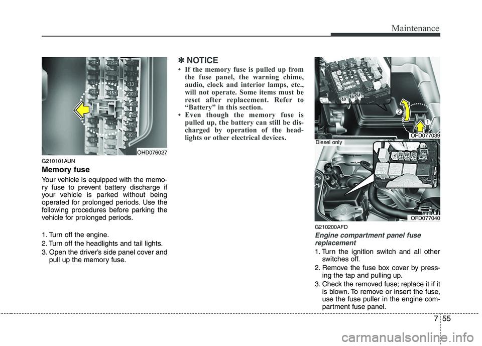
G210101AUN
Memory fuse
Your vehicle is equipped with the memo-
ry fuse to prevent battery discharge if
your vehicle is parked without being
operated for prolonged periods. Use the
following procedures before parking the
vehicle for prolonged periods.
1. Turn off the engine.
2. Turn off the headlights and tail lights.
3. Open the driver’s side panel cover andpull up the memory fuse.
✽✽ NOTICE
If the memory fuse is pulled up from the fuse panel, the warning chime,
audio, clock and interior lamps, etc.,
will not operate. Some items must be
reset after replacement. Refer to
“Battery” in this section.
Even though the memory fuse is
pulled up, the battery can still be dis-
charged by operation of the head-
lights or other electrical devices.
G210200AFD
Engine compartment panel fuse
replacement
1. Turn the ignition switch and all other switches off.
2. Remove the fuse box cover by press- ing the tap and pulling up.
3. Check the removed fuse; replace it if it is blown. To remove or insert the fuse, use the fuse puller in the engine com-
partment fuse panel.
OHD076027
OFD077039
OFD077040
Diesel only
Page 373 of 635
Maintenance
56
7
4. Push in a new fuse of the same rating,
and make sure it fits tightly in the clips.
If it fits loosely, consult an authorized
HYUNDAI dealer.
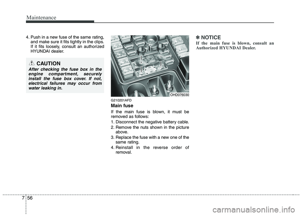
G210201AFD Main fuse
If the main fuse is blown, it must be
removed as follows:
1. Disconnect the negative battery cable.
2. Remove the nuts shown in the pictureabove.
3. Replace the fuse with a new one of the same rating.
4. Reinstall in the reverse order of removal.✽✽ NOTICE
If the main fuse is blown, consult an
Authorized HYUNDAI Dealer.
CAUTION
After checking the fuse box in the engine compartment, securelyinstall the fuse box cover. If not,electrical failures may occur from
water leaking in.
OHD076030
Page 377 of 635
Maintenance
60
7
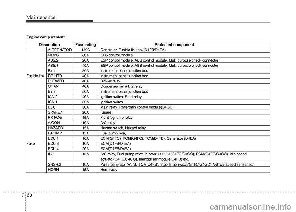
Engine compartment
Description Fuse rating Protected component
ALTERNATOR 150A Generator, Fusible link box(D4FB/D4EA)
MDPS 80A EPS control module
ABS.2 20A ESP control module, ABS control module, Multi purpose check connector
ABS.1 40A ESP control module, ABS control module, Multi purpose check connector
B+.1 50A Instrument panel junction box
Fusible link RR HTD 40A Instrument panel junction box BLOWER 40A Blower relay
C/FAN 40A Condenser fan #1, 2 relay
B+.2 50A Instrument panel junction box
IGN.2 40A Ignition switch, Start relay
IGN.1 30A Ignition switch
ECU 30A Main relay, Powertrain control module(G4GC)
SPARE.1 20A (Spare)
FR FOG 15A Front fog lamp relay
A/CON 10A A/C relay
HAZARD 15A Hazard switch, Hazard relay
F/PUMP 15A Fuel pump relay
ECU.1 10A ECM(G4FC), PCM(G4FC), TCM(D4FB), Generator (D4EA)
Fuse ECU.3 10A ECM(D4FB/D4EA) ECU.4 20A ECM(D4FB/D4EA)
INJ 15A A/C relay, Fuel pump relay, Injector #1,2,3,4(G4FC/G4GC), PCM(G4FC/G4GC), Idle speed actuator(G4FC/G4GC), Immobilizer module(D4FB) etc.
SNSR.2 10A Pulse generator 'A', 'B, 'TCM(D4FB), Stop lamp switch(G4FC/G4GC), Vehicle speed sensor etc.
HORN 15A Horn relay
Page 378 of 635
761
Maintenance
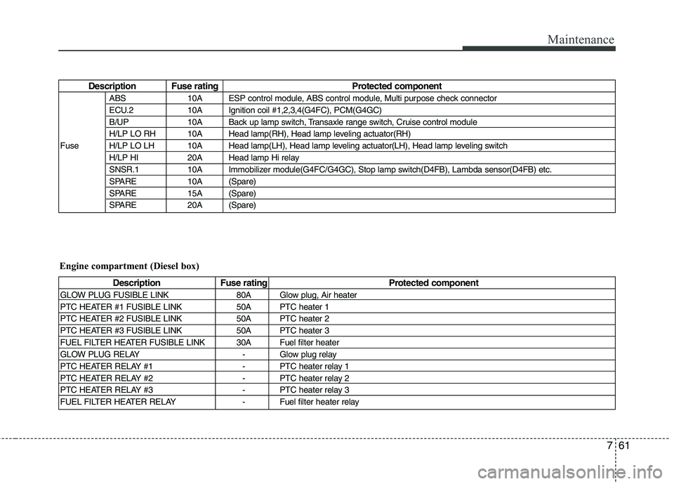
Description Fuse rating Protected componentABS 10A ESP control module, ABS control module, Multi purpose check connector
ECU.2 10A Ignition coil #1,2,3,4(G4FC), PCM(G4GC)
B/UP 10A Back up lamp switch, Transaxle range switch, Cruise control module
H/LP LO RH 10A Head lamp(RH), Head lamp leveling actuator(RH)
Fuse H/LP LO LH 10A Head lamp(LH), Head lamp leveling actuator(LH), Head lamp leveling switch H/LP HI 20A Head lamp Hi relay
SNSR.1 10A Immobilizer module(G4FC/G4GC), Stop lamp switch(D4FB), Lambda sensor(D4FB) etc.
SPARE 10A (Spare)
SPARE 15A (Spare)
SPARE 20A (Spare)
Description Fuse rating Protected component
GLOW PLUG FUSIBLE LINK 80A Glow plug, Air heater
PTC HEATER #1 FUSIBLE LINK 50A PTC heater 1
PTC HEATER #2 FUSIBLE LINK 50A PTC heater 2
PTC HEATER #3 FUSIBLE LINK 50A PTC heater 3
FUEL FILTER HEATER FUSIBLE LINK 30A Fuel filter heater
GLOW PLUG RELAY - Glow plug relay
PTC HEATER RELAY #1 - PTC heater relay 1
PTC HEATER RELAY #2 - PTC heater relay 2
PTC HEATER RELAY #3 - PTC heater relay 3
FUEL FILTER HEATER RELAY - Fuel filter heater relay
Engine compartment (Diesel box)
Page 392 of 635
775
Maintenance
G270300AUN
3. Exhaust emission control system
The Exhaust Emission Control System is
a highly effective system which controls
exhaust emissions while maintaining
good vehicle performance.
G270301AUN
Vehicle modifications
This vehicle should not be modified.
Modification of your vehicle could affect
its performance, safety or durability and
may even violate governmental safety
and emissions regulations.
In addition, damage or performance
problems resulting from any modification
may not be covered under warranty.
G270302AUN
Engine exhaust gas precautions (car- bon monoxide)
Carbon monoxide can be present with other exhaust fumes. Therefore, if you
smell exhaust fumes of any kind inside
your vehicle, have it inspected and
repaired immediately. If you ever sus-
pect exhaust fumes are coming into
your vehicle, drive it only with all the
windows fully open. Have your vehicle
checked and repaired immediately. Do not operate the engine in confined
or closed areas (such as garages) any
more than what is necessary to move
the vehicle in or out of the area.
When the vehicle is stopped in an open area for more than a short time
with the engine running, adjust the
ventilation system (as needed) to draw
outside air into the vehicle.
Never sit in a parked or stopped vehi- cle for any extended time with the
engine running.
When the engine stalls or fails to start, excessive attempts to restart the
engine may cause damage to theemission control system. G270303BFD
Operating precautions for catalytic
converters (if equipped)
Your vehicle is equipped with a catalytic
converter emission control device.
Therefore, the following precautions
must be observed:
Use only UNLEADED FUEL for gaso- line engine.
Do not operate the vehicle when there are signs of engine malfunction, such
as misfire or a noticeable loss of per-
formance.
Do not misuse or abuse the engine. Examples of misuse are coasting withthe ignition off and descending steep
grades in gear with the ignition off.
Do not operate the engine at high idle speed for extended periods (5 minutesor more).
WARNING - Exhaust
Engine exhaust gases contain car-
bon monoxide (CO). Though color-
less and odorless, it is dangerousand could be lethal if inhaled.
Follow the instructions following to
avoid CO poisoning.
WARNING - Fire
A hot exhaust system can ignite
flammable items under your vehi-
cle. Do not park, idle, or drive the
vehicle over or near flammable
objects, such as dry grass, paper,
leaves, etc.