tow HYUNDAI I40 2016 User Guide
[x] Cancel search | Manufacturer: HYUNDAI, Model Year: 2016, Model line: I40, Model: HYUNDAI I40 2016Pages: 534, PDF Size: 11.05 MB
Page 157 of 534
Downloaded from www.Manualslib.com manuals search engine Features of your vehicle
70
4
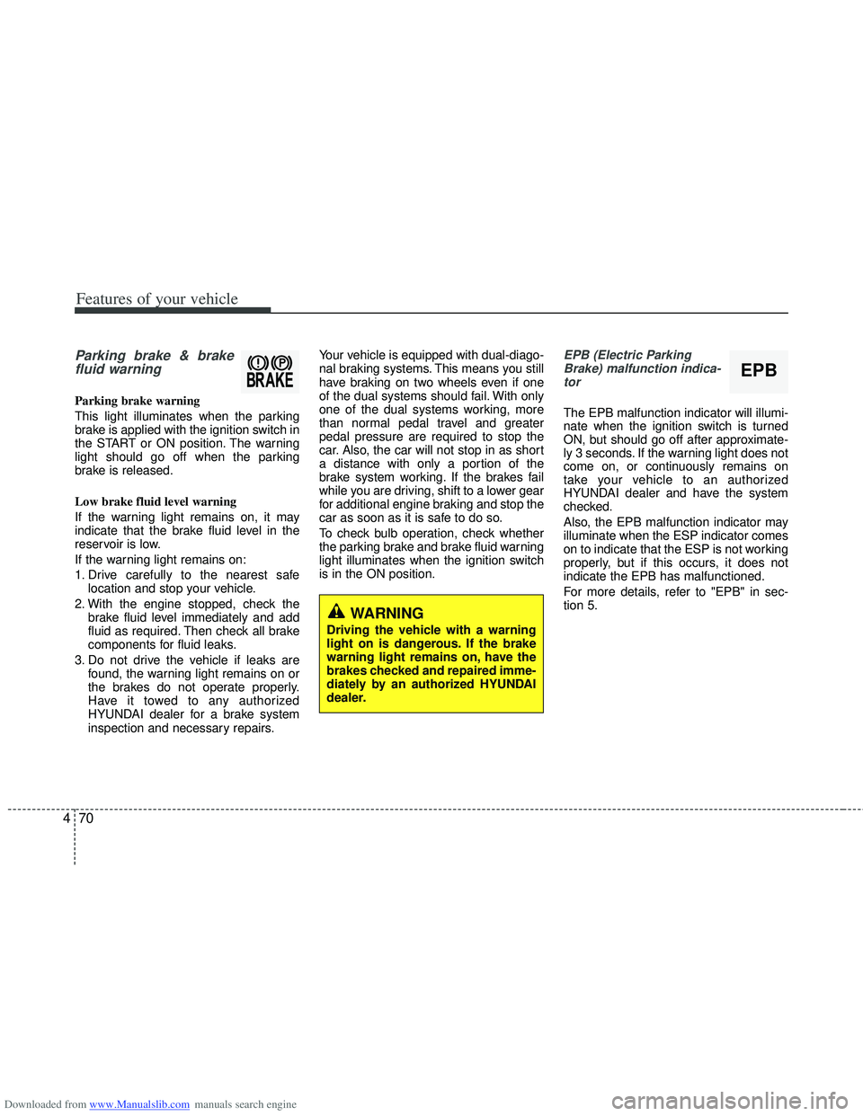
Parking brake & brake
fluid warning
Parking brake warning
This light illuminates when the parking
brake is applied with the ignition switch in
the START or ON position. The warning
light should go off when the parking
brake is released.
Low brake fluid level warning
If the warning light remains on, it may
indicate that the brake fluid level in the
reservoir is low.
If the warning light remains on:
1. Drive carefully to the nearest safe
location and stop your vehicle.
2. With the engine stopped, check the brake fluid level immediately and add
fluid as required. Then check all brake
components for fluid leaks.
3. Do not drive the vehicle if leaks are found, the warning light remains on or
the brakes do not operate properly.
Have it towed to any authorized
HYUNDAI dealer for a brake system
inspection and necessary repairs. Your vehicle is equipped with dual-diago-
nal braking systems. This means you still
have braking on two wheels even if one
of the dual systems should fail. With only
one of the dual systems working, more
than normal pedal travel and greater
pedal pressure are required to stop the
car. Also, the car will not stop in as short
a distance with only a portion of the
brake system working. If the brakes fail
while you are driving, shift to a lower gear
for additional engine braking and stop the
car as soon as it is safe to do so.
To check bulb operation, check whether
the parking brake and brake fluid warning
light illuminates when the ignition switch
is in the ON position.
EPB (Electric Parking
Brake) malfunction indica-tor
The EPB malfunction indicator will illumi-
nate when the ignition switch is turned
ON, but should go off after approximate-
ly 3 seconds. If the warning light does not
come on, or continuously remains on
take your vehicle to an authorized
HYUNDAI dealer and have the system
checked.
Also, the EPB malfunction indicator may
illuminate when the ESP indicator comes
on to indicate that the ESP is not working
properly, but if this occurs, it does not
indicate the EPB has malfunctioned.
For more details, refer to "EPB" in sec-
tion 5.
WARNING
Driving the vehicle with a warning
light on is dangerous. If the brake
warning light remains on, have the
brakes checked and repaired imme-
diately by an authorized HYUNDAI
dealer.
EPB
Page 187 of 534
Downloaded from www.Manualslib.com manuals search engine Features of your vehicle
100
4
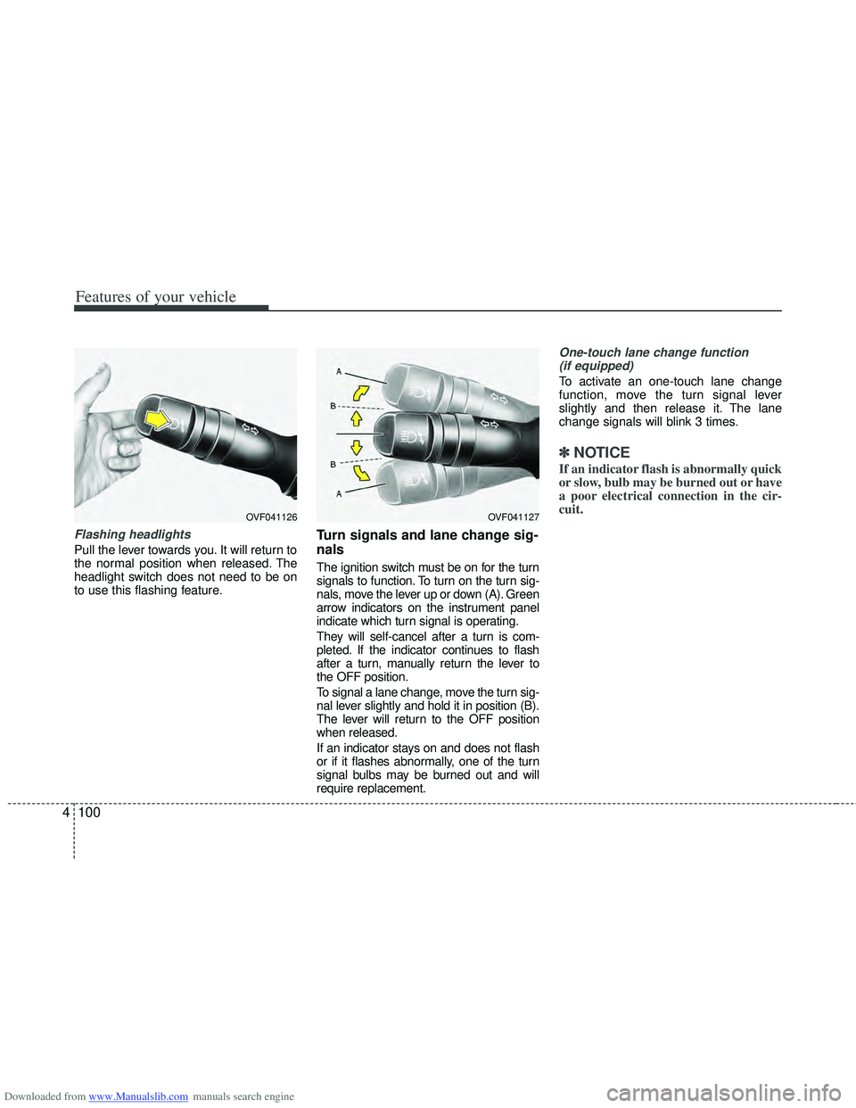
Flashing headlights
Pull the lever towards you. It will return to
the normal position when released. The
headlight switch does not need to be on
to use this flashing feature.
Turn signals and lane change sig-
nals
The ignition switch must be on for the turn
signals to function. To turn on the turn sig-
nals, move the lever up or down (A). Green
arrow indicators on the instrument panel
indicate which turn signal is operating.
They will self-cancel after a turn is com-
pleted. If the indicator continues to flash
after a turn, manually return the lever to
the OFF position.
To signal a lane change, move the turn sig-
nal lever slightly and hold it in position (B).
The lever will return to the OFF position
when released.
If an indicator stays on and does not flash
or if it flashes abnormally, one of the turn
signal bulbs may be burned out and will
require replacement.
One-touch lane change function
(if equipped)
To activate an one-touch lane change
function, move the turn signal lever
slightly and then release it. The lane
change signals will blink 3 times.
✽ ✽ NOTICE
If an indicator flash is abnormally quick
or slow, bulb may be burned out or have
a poor electrical connection in the cir-
cuit.
OVF041127OVF041126
Page 193 of 534
Downloaded from www.Manualslib.com manuals search engine Features of your vehicle
106
4
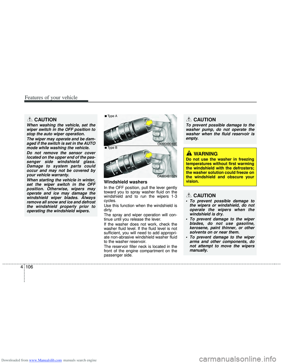
Windshield washers
In the OFF position, pull the lever gently
toward you to spray washer fluid on the
windshield and to run the wipers 1-3
cycles.
Use this function when the windshield is
dirty.
The spray and wiper operation will con-
tinue until you release the lever.
If the washer does not work, check the
washer fluid level. If the fluid level is not
sufficient, you will need to add appropri-
ate non-abrasive windshield washer fluid
to the washer reservoir.
The reservoir filler neck is located in the
front of the engine compartment on the
passenger side.
CAUTION
When washing the vehicle, set the
wiper switch in the OFF position tostop the auto wiper operation.
The wiper may operate and be dam-aged if the switch is set in the AUTOmode while washing the vehicle.
Do not remove the sensor coverlocated on the upper end of the pas-senger side windshield glass.Damage to system parts could occur and may not be covered byyour vehicle warranty.
When starting the vehicle in winter,set the wiper switch in the OFFposition. Otherwise, wipers mayoperate and ice may damage thewindshield wiper blades. Alwaysremove all snow and ice and defrostthe windshield properly prior tooperating the windshield wipers.
OXM049048E
OAM049102N
■Type A
■Type B
CAUTION
To prevent possible damage to the wipers or windshield, do notoperate the wipers when thewindshield is dry.
To prevent damage to the wiper blades, do not use gasoline,kerosene, paint thinner, or othersolvents on or near them.
To prevent damage to the wiper arms and other components, donot attempt to move the wipersmanually.
CAUTION
To prevent possible damage to the
washer pump, do not operate thewasher when the fluid reservoir is empty.
WARNING
Do not use the washer in freezing
temperatures without first warming
the windshield with the defrosters;
the washer solution could freeze on
the windshield and obscure your
vision.
Page 201 of 534
Downloaded from www.Manualslib.com manuals search engine Features of your vehicle
114
4
Face-Level (B, D, F)
Air flow is directed toward the upper body
and face. Additionally, each outlet can be
controlled to direct the air discharged
from the outlet.
Bi-Level (B, D, C, E, F)
Air flow is directed towards the face and
the floor.
Floor-Level (A, C, E, D)
Most of the air flow is directed to the
floor, with a small amount of the air being
directed to the windshield and side win-
dow defrosters.
-
Floor/Defrost-Level (A, C, D, E, F)
Most of the air flow is directed to the floor
and the windshield with a small amount
directed to the side window defrosters.
Defrost-Level (A, D)
Most of the air flow is directed to the
windshield with a small amount of air
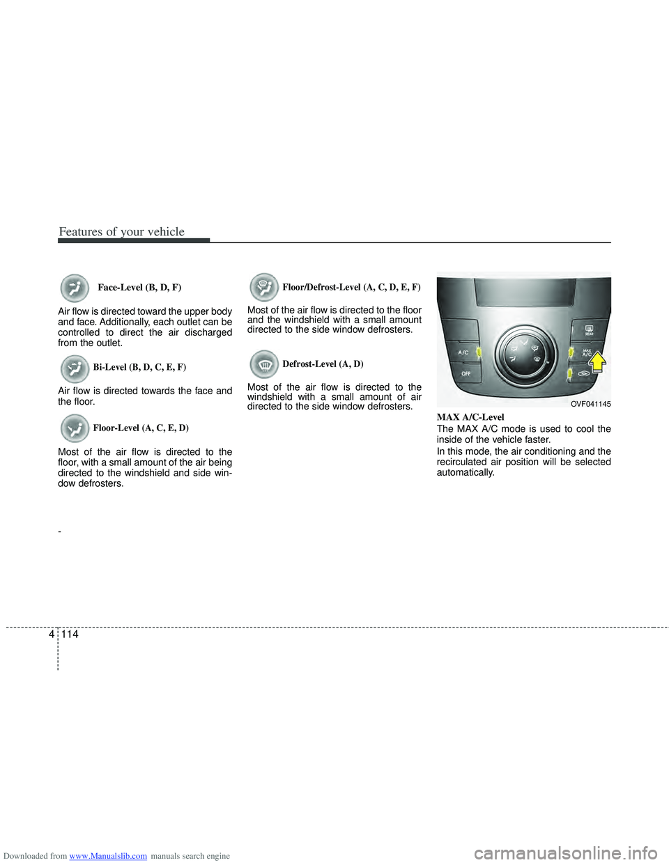
directed to the side window defrosters. MAX A/C-Level
The MAX A/C mode is used to cool the
inside of the vehicle faster.
In this mode, the air conditioning and the
recirculated air position will be selected
automatically.
OVF041145
Page 211 of 534
Downloaded from www.Manualslib.com manuals search engine Features of your vehicle
124
4
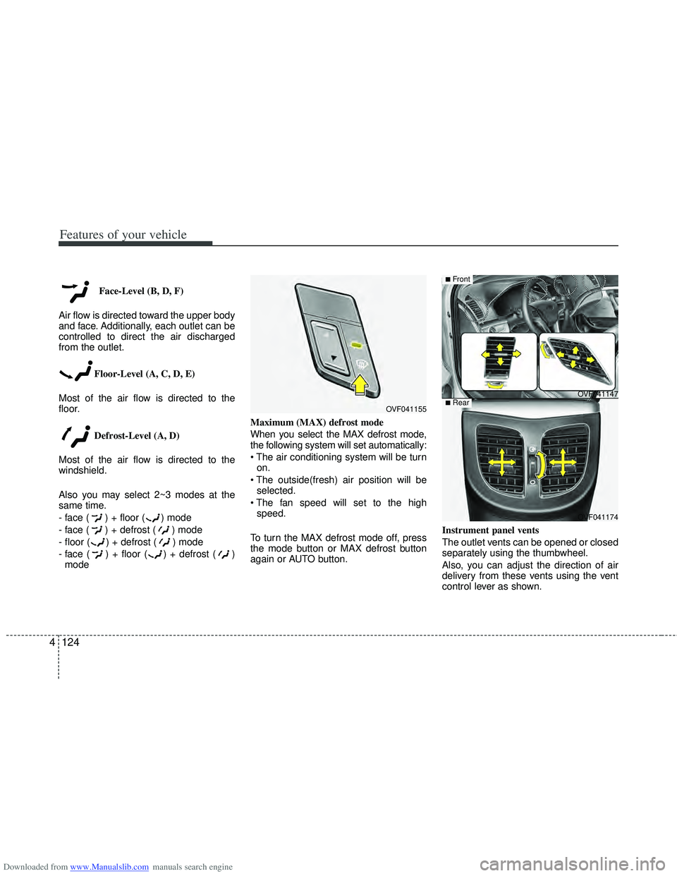
Face-Level (B, D, F)
Air flow is directed toward the upper body
and face. Additionally, each outlet can be
controlled to direct the air discharged
from the outlet.
Floor-Level (A, C, D, E)
Most of the air flow is directed to the
floor.
Defrost-Level (A, D)
Most of the air flow is directed to the
windshield.
Also you may select 2~3 modes at the
same time.
- face ( ) + floor ( ) mode
- face ( ) + defrost ( ) mode
- floor ( ) + defrost ( ) mode
- face ( ) + floor ( ) + defrost ( ) mode Maximum (MAX) defrost mode
When you select the MAX defrost mode,
the following system will set automatically:
on.
selected.
speed.
To turn the MAX defrost mode off, press
the mode button or MAX defrost button
again or AUTO button. Instrument panel vents
The outlet vents can be opened or closed
separately using the thumbwheel.
Also, you can adjust the direction of air
delivery from these vents using the vent
control lever as shown.
OVF041155
OVF041174
■Rear
OVF041147
■Front
Page 222 of 534
Downloaded from www.Manualslib.com manuals search engine 4135
Features of your vehicle
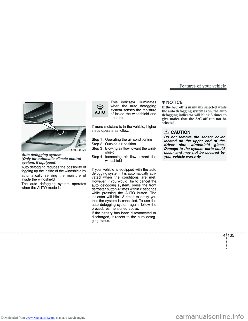
Auto defogging system (Only for automatic climate controlsystem, if equipped)
Auto defogging reduces the possibility of
fogging up the inside of the windshield by
automatically sensing the moisture of
inside the windshield.
The auto defogging system operates
when the AUTO mode is on. This indicator illuminates
when the auto defogging
system senses the moisture
of inside the windshield and
operates.
If more moisture is in the vehicle, higher
steps operate as follow.
Step 1 : Operating the air conditioning
Step 2 : Outside air position
Step 3 : Blowing air flow toward the wind- shield
Step 4 : Increasing air flow toward the windshield
If your vehicle is equipped with the auto
defogging system, it is automatically acti-
vated when the conditions are met.
However, if you would like to cancel the
auto defogging system, press the front
defroster button 4 times within 2 seconds
while pressing the AUTO button. The
indicator will blink 3 times to notify you
that the system is cancelled. To use the
auto defogging system again, follow the
procedures mentioned above.
If the battery has been disconnected or
discharged, it resets to the auto defog-
ging status.
✽ ✽ NOTICE
If the A/C off is manually selected while
the auto defogging system is on, the auto
defogging indicator will blink 3 times to
give notice that the A/C off can not be
selected.
OVF041170
CAUTION
Do not remove the sensor cover
located on the upper end of thedriver side windshield glass. Damage to the system parts couldoccur and may not be covered byyour vehicle warranty.
Page 234 of 534
Downloaded from www.Manualslib.com manuals search engine 4147
Features of your vehicle
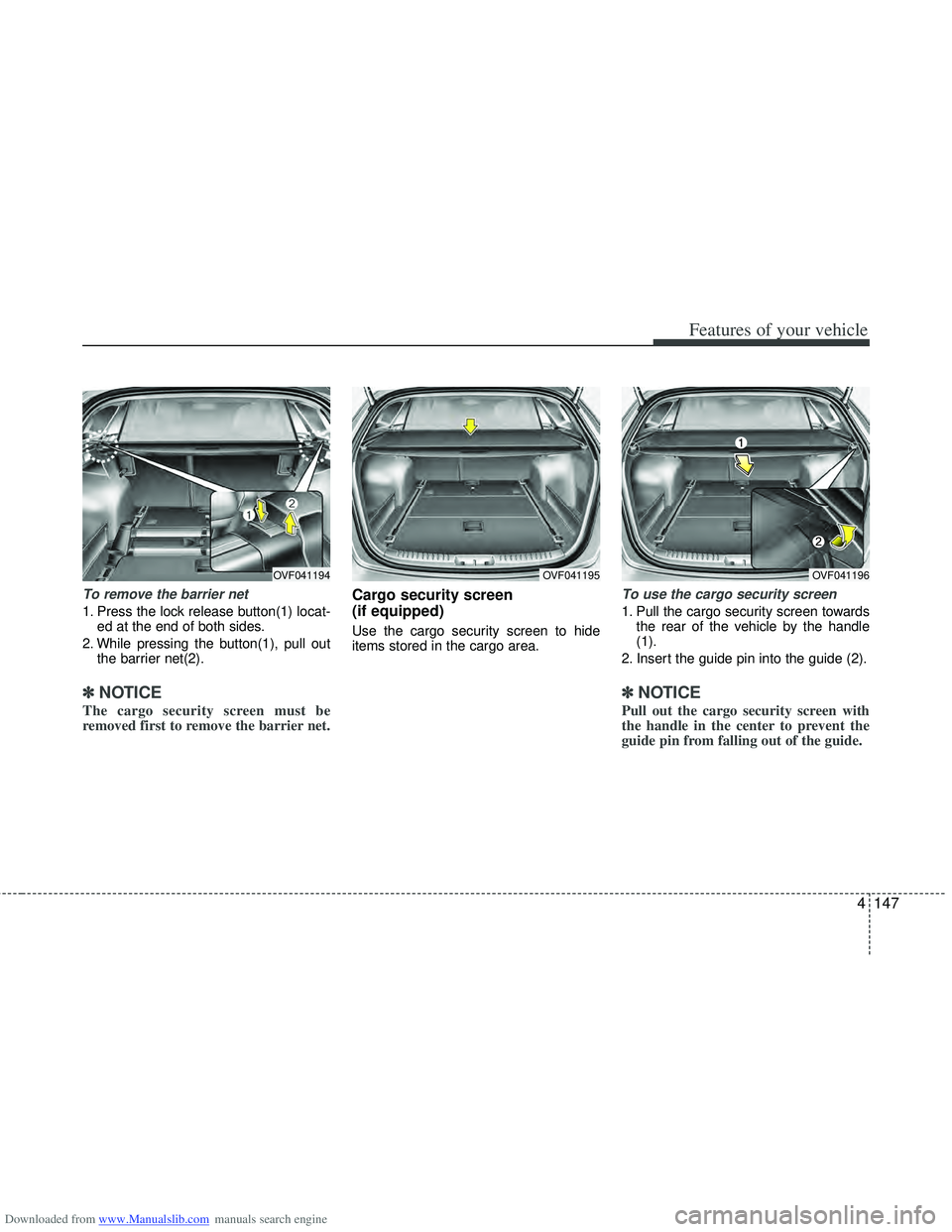
To remove the barrier net
1. Press the lock release button(1) locat-ed at the end of both sides.
2. While pressing the button(1), pull out the barrier net(2).
✽
✽NOTICE
The cargo security screen must be
removed first to remove the barrier net.
Cargo security screen
(if equipped)
Use the cargo security screen to hide
items stored in the cargo area.
To use the cargo security screen
1. Pull the cargo security screen towards
the rear of the vehicle by the handle
(1).
2. Insert the guide pin into the guide (2).
✽ ✽ NOTICE
Pull out the cargo security screen with
the handle in the center to prevent the
guide pin from falling out of the guide.
OVF041194OVF041195OVF041196
Page 235 of 534
Downloaded from www.Manualslib.com manuals search engine Features of your vehicle
148
4
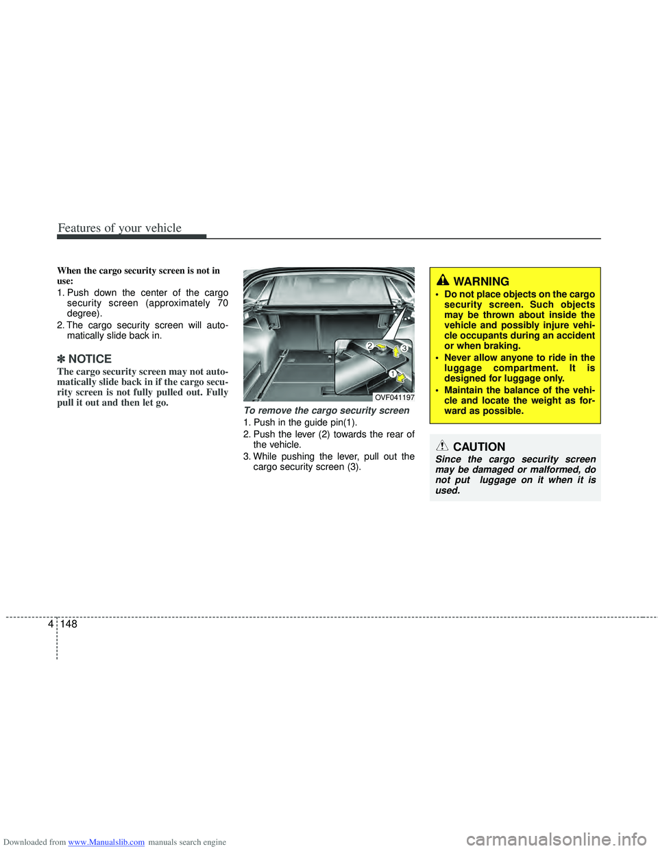
When the cargo security screen is not in
use:
1. Push down the center of the cargo
security screen (approximately 70
degree).
2. The cargo security screen will auto- matically slide back in.
✽ ✽NOTICE
The cargo security screen may not auto-
matically slide back in if the cargo secu-
rity screen is not fully pulled out. Fully
pull it out and then let go.
To remove the cargo security screen
1. Push in the guide pin(1).
2. Push the lever (2) towards the rear of
the vehicle.
3. While pushing the lever, pull out the cargo security screen (3).
WARNING
Do not place objects on the cargosecurity screen. Such objects
may be thrown about inside the
vehicle and possibly injure vehi-
cle occupants during an accident
or when braking.
Never allow anyone to ride in the luggage compartment. It is
designed for luggage only.
Maintain the balance of the vehi- cle and locate the weight as for-
ward as possible.
CAUTION
Since the cargo security screenmay be damaged or malformed, donot put luggage on it when it is used.
OVF041197
Page 242 of 534
Downloaded from www.Manualslib.com manuals search engine 4155
Features of your vehicle
How vehicle audio works
AM and FM radio signals are broadcast
from transmitter towers located around
your city. They are intercepted by the
radio antenna on your vehicle. This signal
is then received by the radio and sent to
your vehicle speakers.
When a strong radio signal has reached
your vehicle, the precise engineering of
your audio system ensures the best pos-
sible quality reproduction. However, in
some cases the signal coming to your
vehicle may not be strong and clear. This
can be due to factors such as the dis-
tance from the radio station, closeness of
other strong radio stations or the pres-
ence of buildings, bridges or other large
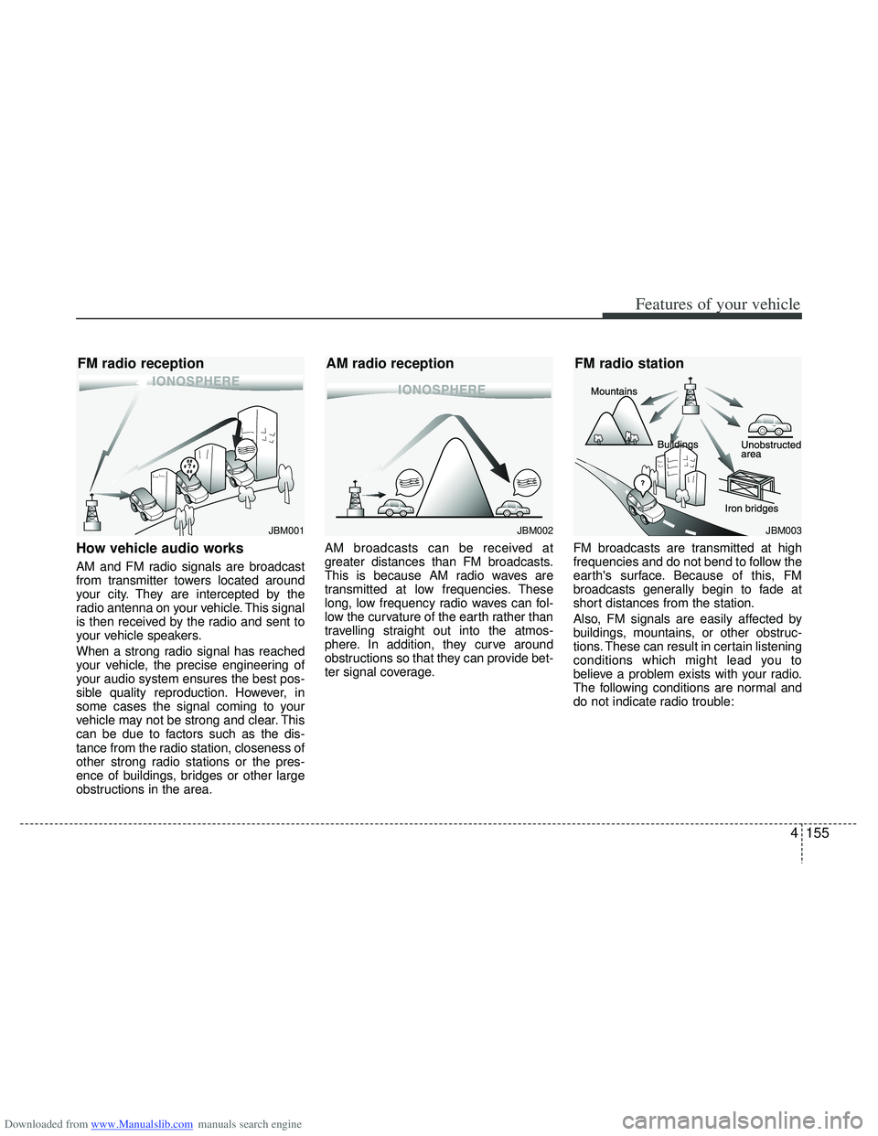
obstructions in the area.AM broadcasts can be received at
greater distances than FM broadcasts.
This is because AM radio waves are
transmitted at low frequencies. These
long, low frequency radio waves can fol-
low the curvature of the earth rather than
travelling straight out into the atmos-
phere. In addition, they curve around
obstructions so that they can provide bet-
ter signal coverage.
FM broadcasts are transmitted at high
frequencies and do not bend to follow the
earth's surface. Because of this, FM
broadcasts generally begin to fade at
short distances from the station.
Also, FM signals are easily affected by
buildings, mountains, or other obstruc-
tions. These can result in certain listening
conditions which might lead you to
believe a problem exists with your radio.
The following conditions are normal and
do not indicate radio trouble:
¢¢¢
JBM001
¢¢¢¢¢¢
JBM002
FM radio reception
AM radio reception
JBM003
FM radio station
Page 294 of 534
Downloaded from www.Manualslib.com manuals search engine 5
Before driving / 5-3
Key positions / 5-4
Engine start/stop button / 5-8
ISG (Idle Stop and Go) system / 5-14
Manual transaxle / 5-19
Automatic transaxle / 5-22
Brake system / 5-29
Cruise control system / 5-48
Speed limit control system / 5-53
Lane keeping assist system (LKAS) / 5-56
Economical operation / 5-63
Special driving conditions / 5-65
Winter driving / 5-69
Trailer towing / 5-73
Vehicle weight / 5-82
Driving your vehicle