brake HYUNDAI IONIQ 5 2023 Owners Manual
[x] Cancel search | Manufacturer: HYUNDAI, Model Year: 2023, Model line: IONIQ 5, Model: HYUNDAI IONIQ 5 2023Pages: 680, PDF Size: 48.22 MB
Page 11 of 680
Foreword / Electric Vehicle System Overview
1-6
VeHiCle data ColleCtion and eVent data reCorderS
This vehicle is equipped with an event data recorder (EDR). The main purpose of
an EDR is to record, in certain crash or near crash-like situations, such as an air bag
deployment or hitting a road obstacle, data that will assist in understanding how a
vehicle’s systems performed. The EDR is designed to record data related to vehicle
dynamics and safety systems for a short period of time, typically 30 seconds or less.
The EDR in this vehicle is designed to record such data as: • How various systems in your vehicle were operating;
• Whether or not the driver and passenger safety belts were buckled/ fastened;
• How far (if at all) the driver was depressing the accelerator and/or brake pedal; and,
• How fast the vehicle was traveling.
These data can help provide a better understanding of the circumstances in which
crashes and injuries occur. NOTE: EDR data are recorded by your vehicle only if a non-
trivial crash situation occurs; no data are recorded by the EDR under normal driving
conditions and no personal data (for example, name, gender, age, and crash location)
are recorded. However, other parties, such as law enforcement, could combine the
EDR data with the type of personally identifying data routinely acquired during a crash
investigation.
To read data recorded by an EDR, special equipment is required, and access to the
vehicle or the EDR is needed. In addition to the vehicle manufacturer, other parties,
such as law enforcement, that have the special equipment, can read the information if
they have access to the vehicle or the EDR.
Page 27 of 680
Foreword / Electric Vehicle System Overview
1-22
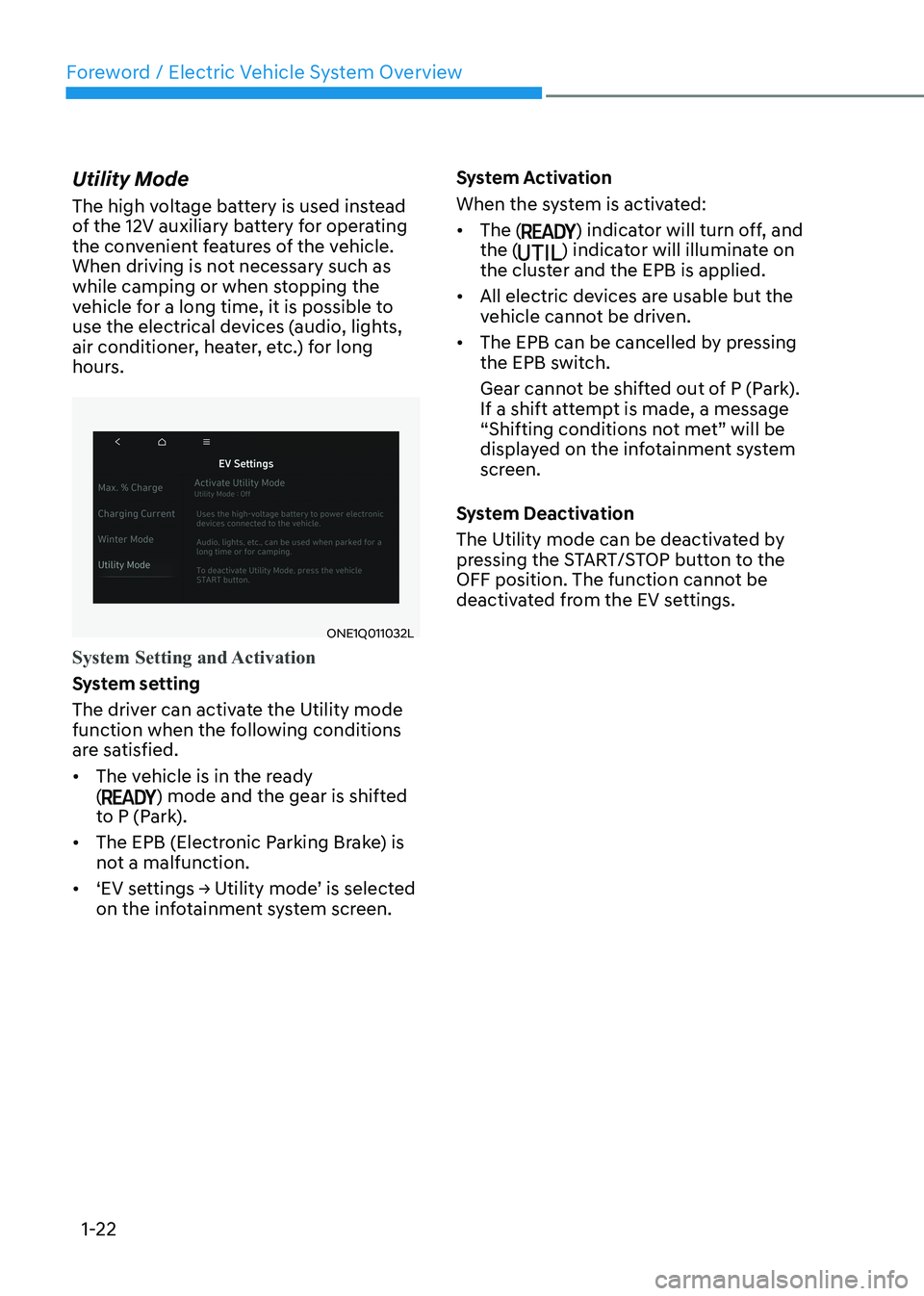
Utility Mode
The high voltage battery is used instead
of the 12V auxiliary battery for operating
the convenient features of the vehicle.
When driving is not necessary such as
while camping or when stopping the
vehicle for a long time, it is possible to
use the electrical devices (audio, lights,
air conditioner, heater, etc.) for long
hours.
ONE1Q011032L
System Setting and Activation
System setting
The driver can activate the Utility mode
function when the following conditions
are satisfied. •
The vehicle is in the ready (
) mode and the gear is shifted
to P (Park).
• The EPB (Electronic Parking Brake) is
not a malfunction.
• ‘EV settings → Utility mode’ is selected on the infotainment system screen. System Activation
When the system is activated:•
The (
) indicator will turn off, and
the () indicator will illuminate on
the cluster and the EPB is applied.
• All electric devices are usable but the
vehicle cannot be driven.
• The EPB can be cancelled by pressing
the EPB switch.
Gear cannot be shifted out of P (Park).
If a shift attempt is made, a message
“Shifting conditions not met” will be
displayed on the infotainment system
screen.
System Deactivation
The Utility mode can be deactivated by
pressing the START/STOP button to the
OFF position. The function cannot be
deactivated from the EV settings.
Page 36 of 680
01
1-31
How to Connect AC Charger
1. Depress the brake pedal and apply the
parking brake.
2. Turn OFF all switches, shift to P (Park), and turn OFF the vehicle.
If charging is initiated without the
gear in P (Park), the charging will start
after the gear is automatically shifted
to P (Park).
ONE1Q011040
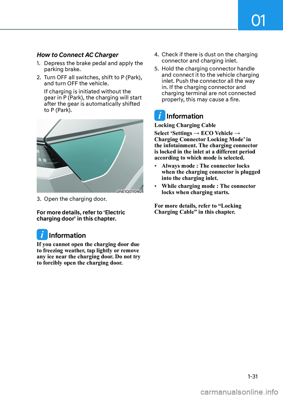
3. Open the charging door.
For more details, refer to ‘Electric
charging door’ in this chapter.
Information
If you cannot open the charging door due
to freezing weather, tap lightly or remove
any ice near the charging door. Do not try
to forcibly open the charging door. 4.
Check if there is dust on the charging
connector and charging inlet.
5. Hold the charging connector handle and connect it to the vehicle charging
inlet. Push the connector all the way
in. If the charging connector and
charging terminal are not connected
properly, this may cause a fire.
Information
Locking Charging Cable
Select ‘Settings → ECO Vehicle →
Charging Connector Locking Mode’ in
the infotainment. The charging connector
is locked in the inlet at a different period according to which mode is selected. • Always mode : The connector locks
when the charging connector is plugged into the charging inlet.
• While charging mode : The connector locks when charging starts.
For more details, refer to “Locking
Charging Cable” in this chapter.
Page 39 of 680
Foreword / Electric Vehicle System Overview
1-34
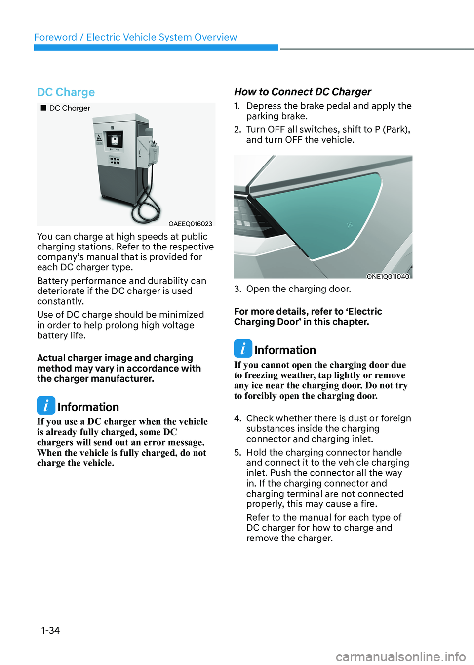
DC Charge
„„DC Charger
OAEEQ016023
You can charge at high speeds at public
charging stations. Refer to the respective
company’s manual that is provided for
each DC charger type.
Battery performance and durability can
deteriorate if the DC charger is used
constantly.
Use of DC charge should be minimized
in order to help prolong high voltage
battery life.
Actual charger image and charging
method may vary in accordance with
the charger manufacturer.
Information
If you use a DC charger when the vehicle
is already fully charged, some DC
chargers will send out an error message. When the vehicle is fully charged, do not charge the vehicle. How to Connect DC Charger
1. Depress the brake pedal and apply the
parking brake.
2. Turn OFF all switches, shift to P (Park), and turn OFF the vehicle.
ONE1Q011040
3. Open the charging door.
For more details, refer to ‘Electric
Charging Door’ in this chapter.
Information
If you cannot open the charging door due
to freezing weather, tap lightly or remove
any ice near the charging door. Do not try
to forcibly open the charging door.
4. Check whether there is dust or foreign
substances inside the charging
connector and charging inlet.
5. Hold the charging connector handle and connect it to the vehicle charging
inlet. Push the connector all the way
in. If the charging connector and
charging terminal are not connected
properly, this may cause a fire.
Refer to the manual for each type of
DC charger for how to charge and
remove the charger.
Page 44 of 680
01
1-39
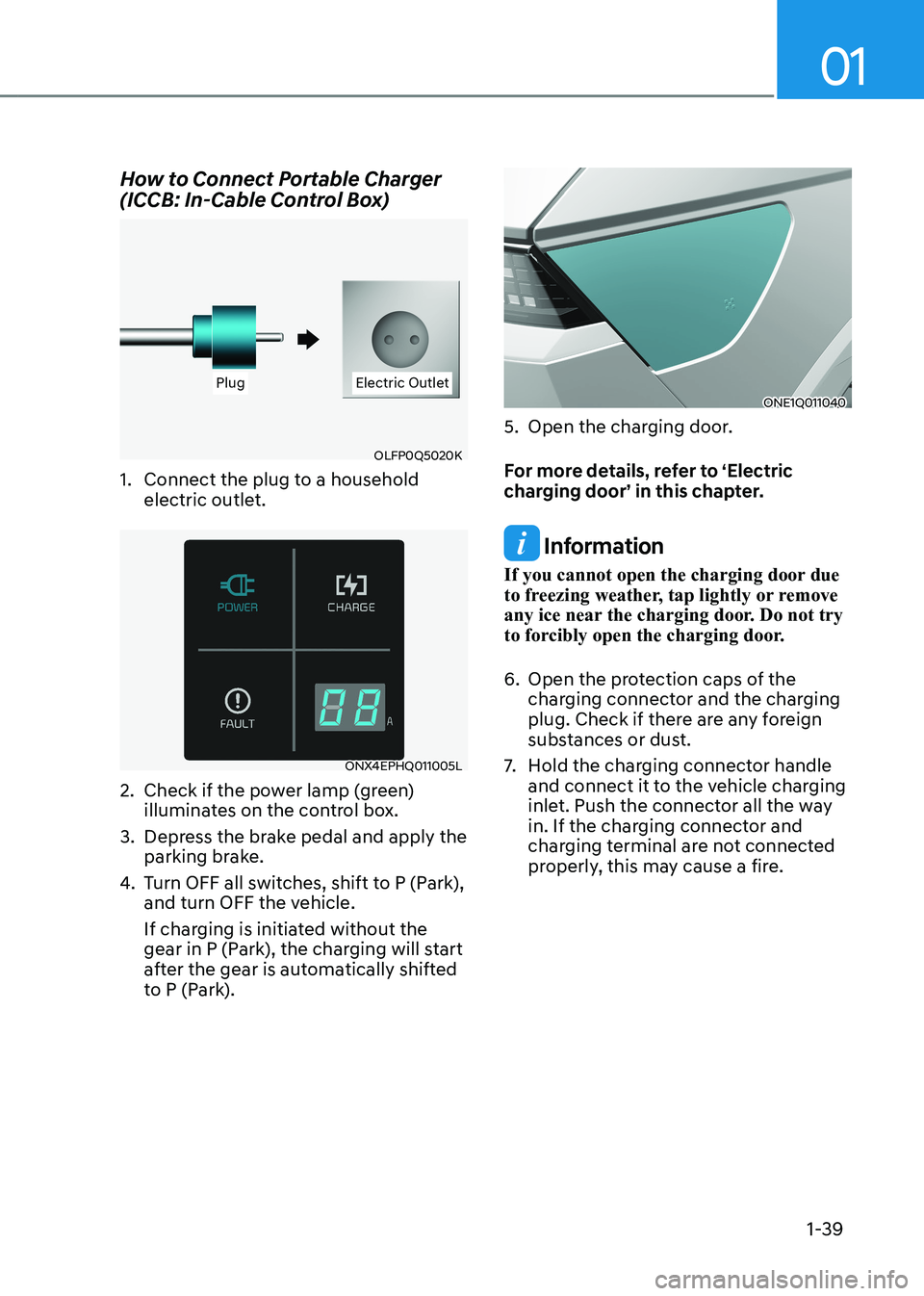
How to Connect Portable Charger
(ICCB: In-Cable Control Box)
PlugPlug Electric OutletElectric Outlet
OLFP0Q5020K
1. Connect the plug to a household electric outlet.
ONX4EPHQ011005L
2. Check if the power lamp (green) illuminates on the control box.
3. Depress the brake pedal and apply the parking brake.
4. Turn OFF all switches, shift to P (Park),
and turn OFF the vehicle.
If charging is initiated without the
gear in P (Park), the charging will start
after the gear is automatically shifted
to P (Park).
ONE1Q011040
5. Open the charging door.
For more details, refer to ‘Electric
charging door’ in this chapter.
Information
If you cannot open the charging door due
to freezing weather, tap lightly or remove
any ice near the charging door. Do not try
to forcibly open the charging door.
6. Open the protection caps of the charging connector and the charging
plug. Check if there are any foreign
substances or dust.
7. Hold the charging connector handle
and connect it to the vehicle charging
inlet. Push the connector all the way
in. If the charging connector and
charging terminal are not connected
properly, this may cause a fire.
Page 55 of 680
Foreword / Electric Vehicle System Overview
1-50
driVing eleCtriC VeHiCle
How to Start the Vehicle
1. Holding the smart key, sit in the driver’s seat.
2. Fasten the seat belt before starting the vehicle.
3. Make sure to engage the parking brake.
4. Turn OFF all electrical devices.
5. Make sure to depress and hold the brake pedal.
6. While depressing the brake pedal, shift to P (Park).
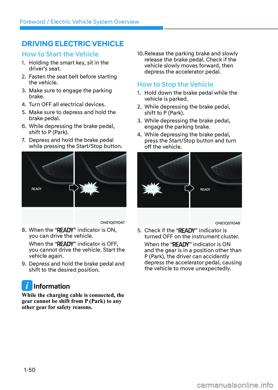
7. Depress and hold the brake pedal
while pressing the Start/Stop button.
ONE1Q011047
8. When the “
” indicator is ON,
you can drive the vehicle. When the “
” indicator is OFF,
you cannot drive the vehicle. Start the
vehicle again.
9. Depress and hold the brake pedal and
shift to the desired position.
Information
While the charging cable is connected, the
gear cannot be shift from P (Park) to any
other gear for safety reasons. 10. Release the parking brake and slowly
release the brake pedal. Check if the
vehicle slowly moves forward, then
depress the accelerator pedal.
How to Stop the Vehicle
1. Hold down the brake pedal while the
vehicle is parked.
2. While depressing the brake pedal, shift to P (Park).
3. While depressing the brake pedal, engage the parking brake.
4. While depressing the brake pedal,
press the Start/Stop button and turn
off the vehicle.
ONE1Q011048
5. Check if the “
” indicator is
turned OFF on the instrument cluster. When the “
” indicator is ON
and the gear is in a position other than
P (Park), the driver can accidently
depress the accelerator pedal, causing
the vehicle to move unexpectedly.
Page 59 of 680
Foreword / Electric Vehicle System Overview
1-54
3. ‘Electronics’ shows the power and
energy consumption which are used
by the vehicle systems including the
cluster, infotainment system(speaker
and navigation), headlamp, vehicle
control unit, etc.
4. ‘Driving’ shows the total power
and energy consumption of the
driving motor’s driving energy and
regenerative energy.
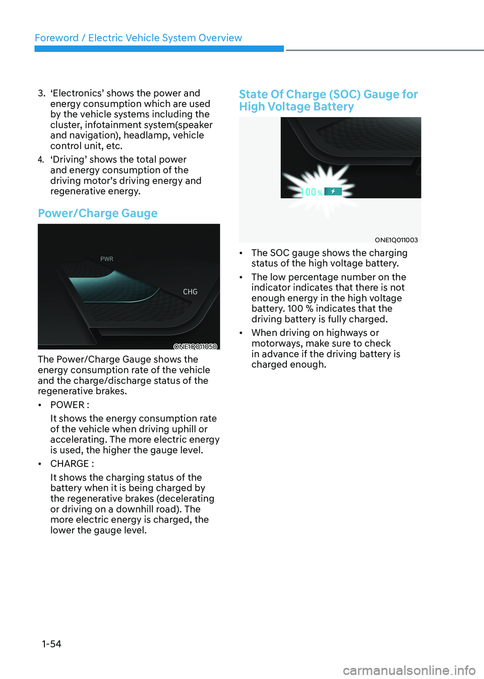
Power/Charge Gauge
ONE1Q011050
The Power/Charge Gauge shows the
energy consumption rate of the vehicle
and the charge/discharge status of the
regenerative brakes. • POWER :
It shows the energy consumption rate
of the vehicle when driving uphill or
accelerating. The more electric energy
is used, the higher the gauge level.
• CHARGE :
It shows the charging status of the
battery when it is being charged by
the regenerative brakes (decelerating
or driving on a downhill road). The
more electric energy is charged, the
lower the gauge level.
State Of Charge (SOC) Gauge for
High Voltage Battery
ONE1Q011003
• The SOC gauge shows the charging
status of the high voltage battery.
• The low percentage number on the
indicator indicates that there is not
enough energy in the high voltage
battery. 100 % indicates that the
driving battery is fully charged.
• When driving on highways or
motorways, make sure to check
in advance if the driving battery is
charged enough.
Page 62 of 680
01
1-57
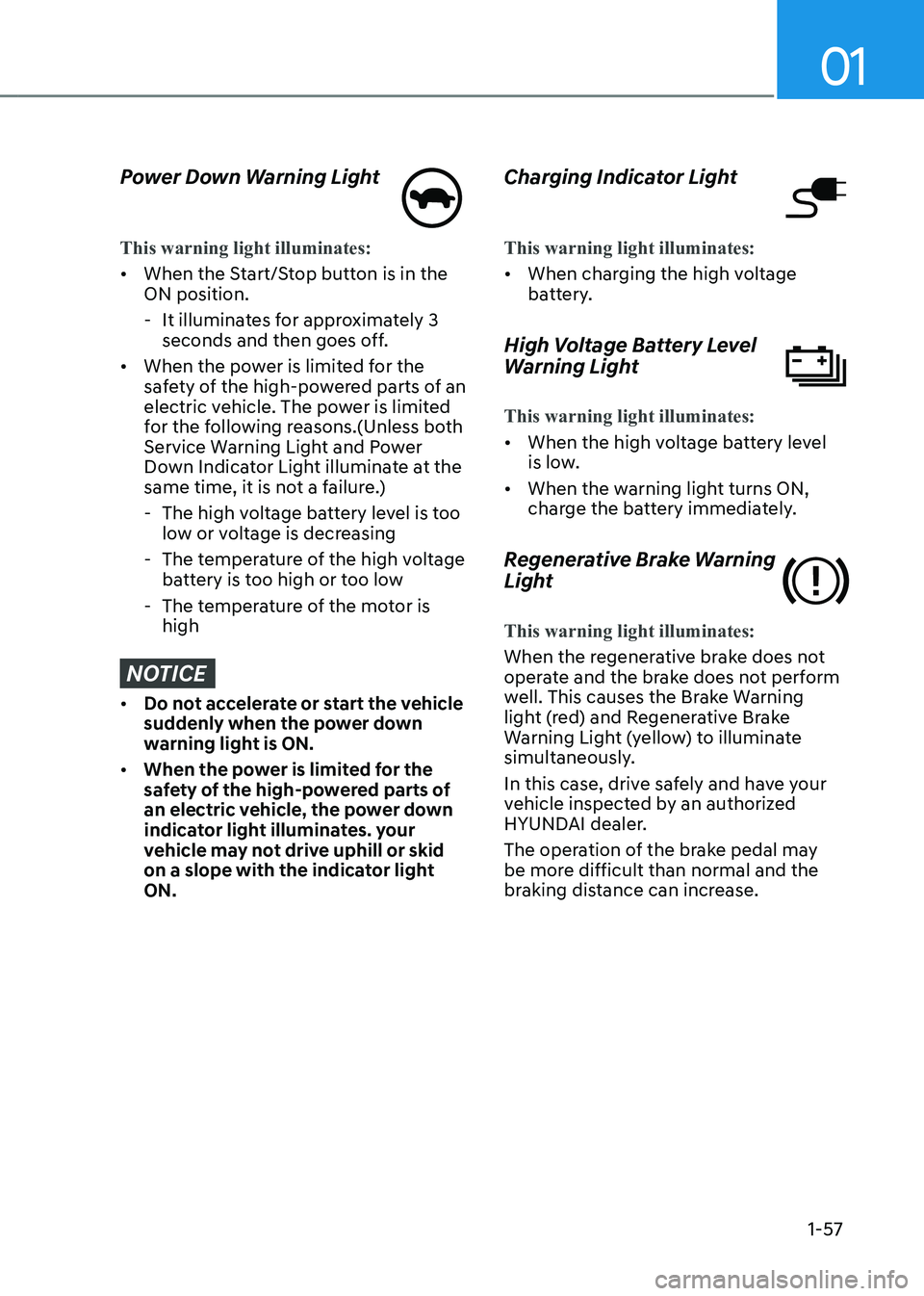
Power Down Warning Light
This warning light illuminates:
• When the Start/Stop button is in the ON position.
- It illuminates for approximately 3 seconds and then goes off.
• When the power is limited for the
safety of the high-powered parts of an
electric vehicle. The power is limited
for the following reasons.(Unless both
Service Warning Light and Power
Down Indicator Light illuminate at the
same time, it is not a failure.)
- The high voltage battery level is too low or voltage is decreasing
- The temperature of the high voltage battery is too high or too low
- The temperature of the motor is high
NOTICE
• Do not accelerate or start the vehicle
suddenly when the power down
warning light is ON.
• When the power is limited for the
safety of the high-powered parts of
an electric vehicle, the power down
indicator light illuminates. your
vehicle may not drive uphill or skid
on a slope with the indicator light ON. Charging Indicator Light
This warning light illuminates:
•
When charging the high voltage
battery.
High Voltage Battery Level
Warning Light
This warning light illuminates:
• When the high voltage battery level
is low.
• When the warning light turns ON,
charge the battery immediately.
Regenerative Brake Warning
Light
This warning light illuminates:
When the regenerative brake does not
operate and the brake does not perform
well. This causes the Brake Warning
light (red) and Regenerative Brake
Warning Light (yellow) to illuminate
simultaneously.
In this case, drive safely and have your
vehicle inspected by an authorized
HYUNDAI dealer.
The operation of the brake pedal may
be more difficult than normal and the
braking distance can increase.
Page 64 of 680
01
1-59
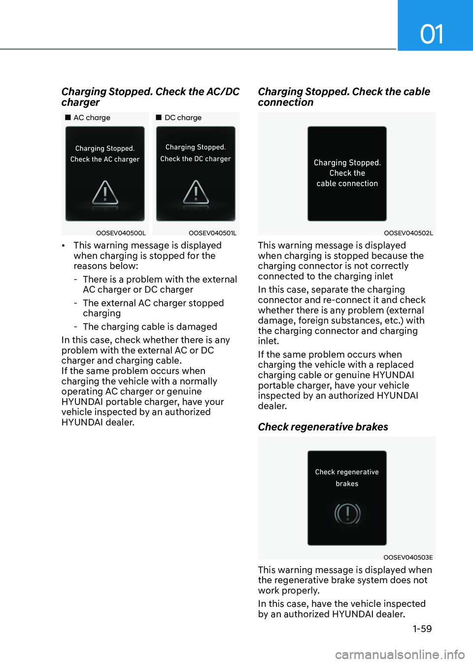
Charging Stopped. Check the AC/DC
charger
„„AC charge
„„DC charge
OOSEV040500LOOSEV040501L
• This warning message is displayed
when charging is stopped for the
reasons below:
- There is a problem with the external AC charger or DC charger
- The external AC charger stopped charging
- The charging cable is damaged
In this case, check whether there is any
problem with the external AC or DC
charger and charging cable.
If the same problem occurs when
charging the vehicle with a normally
operating AC charger or genuine
HYUNDAI portable charger, have your
vehicle inspected by an authorized
HYUNDAI dealer. Charging Stopped. Check the cable
connectionOOSEV040502L
This warning message is displayed
when charging is stopped because the
charging connector is not correctly
connected to the charging inlet
In this case, separate the charging
connector and re-connect it and check
whether there is any problem (external
damage, foreign substances, etc.) with
the charging connector and charging
inlet.
If the same problem occurs when
charging the vehicle with a replaced
charging cable or genuine HYUNDAI
portable charger, have your vehicle
inspected by an authorized HYUNDAI
dealer.
Check regenerative brakes
OOSEV040503E
This warning message is displayed when
the regenerative brake system does not
work properly.
In this case, have the vehicle inspected
by an authorized HYUNDAI dealer.
Page 74 of 680
2-4
Vehicle Information, Consumer Information and Reporting Safety Defects
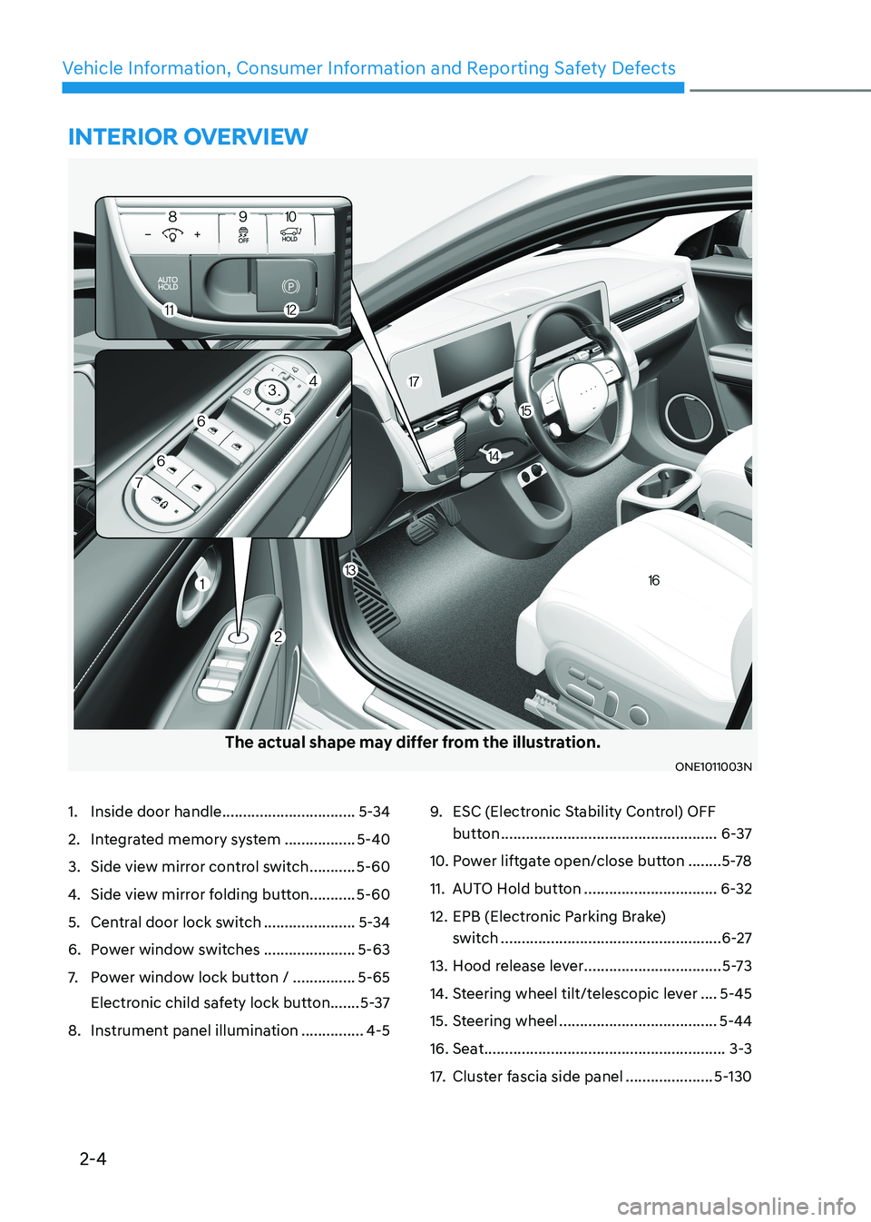
The actual shape may differ from the illustration.
ONE1011003N
1. Inside door handle ................................5-34
2. Integrated memory system .................5-40
3. Side view mirror control switch ...........5-60
4. Side view mirror folding button........... 5-60
5. Central door lock switch ......................5-34
6. Power window switches ......................5-63
7. Power window lock button / ...............5-65
Electronic child safety lock button .......5-37
8. Instrument panel illumination ...............4-59.
ESC (Electronic Stability Control) OFF
button .................................................... 6-37
10. Power liftgate open/close button ........5-78
11. AUTO Hold button ................................6-32
12. EPB (Electronic Parking Brake) switch ..................................................... 6-27
13. Hood release lever .................................5-73
14. Steering wheel tilt/telescopic lever ....5-45
15. Steering wheel ...................................... 5-44
16. Seat .......................................................... 3-3
17. Cluster fascia side panel .....................5-130
InterIor overvIew