clock Hyundai Ioniq Electric 2018 Owner's Manual
[x] Cancel search | Manufacturer: HYUNDAI, Model Year: 2018, Model line: Ioniq Electric, Model: Hyundai Ioniq Electric 2018Pages: 541, PDF Size: 19.83 MB
Page 20 of 541
Safety Precautions
Adjusting the seats so that you are sit-
ting in a safe, comfortable position
plays an important role in driver and
passenger safety together with the
seat belts and air bags in an accident.
Air bags
You can take steps to reduce the risk
of being injured by an inflating air
bag. Sitting too close to an air bag
greatly increases the risk of injury in
the event the air bag inflates.
The National Highway Traffic Safety
Administration (NHTSA) recommends
that drivers allow at least 10 inches
(25 cm) between the center of the
steering wheel and their chest.
Do not use a cushion that
reduces friction between the seat
and the passenger. The passen-
ger's hips may slide under the
lap portion of the seat belt during
an accident or a sudden stop.
Serious or fatal internal injuries
could result because the seat
belt cannot operate properly.
WARNING
To reduce the risk of serious
injury or death from an inflating
air bag, take the following pre-
cautions:
•Adjust the driver's seat as far to
the rear as possible while main-
taining the ability to maintain
full control of the vehicle.
Adjust the front passenger seat
as far to the rear as possible.
Hold the steering wheel by the
rim with hands at the 9 o'clock
and 3 o'clock positions to mini-
mize the risk of injuries to your
hands and arms.
NEVER place anything or any-
one between the steering wheel
and the air bag.
Do not allow the front passen-
ger to place feet or legs on the
dashboard to minimize the risk
of leg injuries.
WARNING
2-5
Safety system of your vehicle
2
Page 66 of 541
2-51
Safety system of your vehicle
2
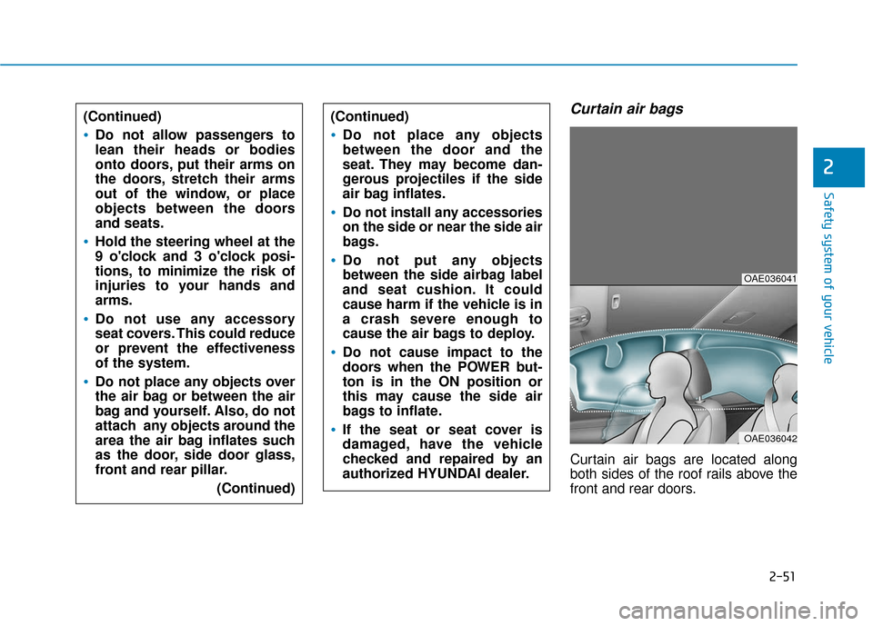
Curtain air bags
Curtain air bags are located along
both sides of the roof rails above the
front and rear doors.
(Continued)
Do not allow passengers to
lean their heads or bodies
onto doors, put their arms on
the doors, stretch their arms
out of the window, or place
objects between the doors
and seats.
Hold the steering wheel at the
9 o'clock and 3 o'clock posi-
tions, to minimize the risk of
injuries to your hands and
arms.
Do not use any accessory
seat covers. This could reduce
or prevent the effectiveness
of the system.
Do not place any objects over
the air bag or between the air
bag and yourself. Also, do not
attach any objects around the
area the air bag inflates such
as the door, side door glass,
front and rear pillar.
(Continued)
(Continued)
Do not place any objects
between the door and the
seat. They may become dan-
gerous projectiles if the side
air bag inflates.
Do not install any accessories
on the side or near the side air
bags.
Do not put any objects
between the side airbag label
and seat cushion. It could
cause harm if the vehicle is in
a crash severe enough to
cause the air bags to deploy.
Do not cause impact to the
doors when the POWER but-
ton is in the ON position or
this may cause the side air
bags to inflate.
If the seat or seat cover is
damaged, have the vehicle
checked and repaired by an
authorized HYUNDAI dealer.
OAE036041
OAE036042
Page 70 of 541
2-55
Safety system of your vehicle
2
To help provide protection, the airbags must inflate rapidly. The speed
of air bag inflation is a consequence
of extremely short time in which to
inflate the air bag between the
occupant and the vehicle structures
before the occupant impacts those
structures. This speed of inflation
reduces the risk of serious or life-
threatening injuries and is thus a
necessary part of air bag design.
However, the rapid air bag inflation
can also cause injuries which can
include facial abrasions, bruises and
broken bones because the inflation
speed also causes the air bags to
expand with a great deal of force.
There are even circumstances under which contact with the air
bag can cause fatal injuries, espe-
cially if the occupant is positioned
excessively close to the air bag.
You can take steps to help reduce
the risk of being injured by an inflat-
ing air bag. The greatest risk is sitting
too close to the air bag. An air bag
needs about 10 inches (25 cm) of
space to inflate. NHTSA recom-
mends that drivers allow at least 10
inches (25 cm) between the center of
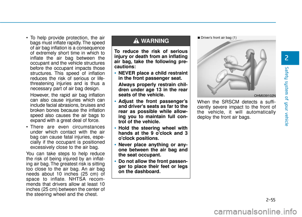
the steering wheel and the chest. When the SRSCM detects a suffi-
ciently severe impact to the front of
the vehicle, it will automatically
deploy the front air bags.
OHM039102N
■Driver’s front air bag (1)
To reduce the risk of serious
injury or death from an inflating
air bag, take the following pre-
cautions:
NEVER place a child restraint
in the front passenger seat.
Always properly restrain chil-
dren under age 13 in the rear
seats of the vehicle.
Adjust the front passenger’s
and driver's seats as far to the
rear as possible while allow-
ing you to maintain full con-
trol of the vehicle.
Hold the steering wheel with
hands at the 9 o'clock and 3
o'clock positions.
Never place anything or any-
one between the air bag and
the seat occupant.
Do not allow the front passen-
ger to place their feet or legs
on the dashboard.
WARNING
Page 87 of 541
Wipers and Washers..........................................3-103
Windshield Wipers ........................................................3-103
Windshield Washers .....................................................3-104
Driver Assist System .........................................3-105
Rear View Camera ........................................................3-105
Defroster .............................................................3-106
Rear Window Defroster ..............................................3-106
Automatic Climate Control System ..................3-107
Automatic Heating and Air Conditioning.................3-108
Manual Heating and Air Conditioning......................3-109
System Operation .........................................................3-117
System Maintenance....................................................3-118
Windshield Defrosting and Defogging ............3-120
To Defog Inside Windshield ........................................3-120
To Defrost Outside Windshield ..................................3-121
Defogging Logic ............................................................3-121
Auto Defogging System ..............................................3-121
Climate Control Additional Features ...............3-123
Automatic Ventilation ...................................................3-123
Storage Compartment .......................................3-123
Center Console Storage ..............................................3-123
Glove Box ........................................................................\
3-124
Sunglass Holder.............................................................3-124
Multi Box ........................................................................\
.3-125
Interior Features ................................................3-125
Cup Holder ......................................................................3-\
125
Sunvisor ........................................................................\
...3-126
Power Outlet ..................................................................3-127
Wireless Cellular Phone Charging System..............3-128
Clock ........................................................................\
.........3-129
Clothes Hanger ..............................................................3-130
Floor Mat Anchor(s).....................................................3-130
Cargo Security Screen .................................................3-131
3
Page 214 of 541
3-129
Convenient features of your vehicle
3
(Continued)
Locate your cell phone well inthe middle of the wireless cellu-
lar phone charging system.
Even when your cell phone
locates slightly to one side, the
charging speed may decrease.
The wireless charging process may temporarily stop, when a
smart key function operates (i.e.
starting the vehicle, opening the
doors, closing the doors).
For certain cell phones, the indi- cator color may not change to
green, even when the wireless
charging process is properly
completed.
The wireless charging process may temporarily stop, when tem-
perature abnormally increases
inside the wireless cellular phone
charging system. The wireless
charging process restarts, when
temperature falls to a proper level.
The wireless charging process may temporarily stop when
there is any metallic item, such
as a coin, between the wireless
cellular phone charging system
and a cellular phone.ClockVehicles with Audio system
Select the [SETUP] button on the
audio system ➟ Select [Date/Time].
Set time : Set the time displayed on the audio screen.
Time format : Choose between 12- hour and 24-hour time formats.
Vehicles with Navigation system
Select the Settings menu on the
Navigation system ➟Select
[Date/Time].
GPS time : Displays time according to the received GNSS time.
24-hour : Switches to 12 hour or 24 hour.
Do not adjust the clock while
driving, you may lose your
steering control and cause an
accident that results in severe
personal injury or death.
WARNING
Page 220 of 541
4-3
Multimedia System
4
Roof antenna
The roof antenna receives both AM
and FM broadcast signals. Rotate
the roof antenna in a counterclock-
wise direction to remove it. Rotate it
in a clockwise direction to reinstall it.
Before entering a place with a lowheight clearance or a car wash,
remove the antenna by rotating it
counterclockwise. If not, the
antenna may be damaged.
When reinstalling your antenna, it is important that it is fully
tightened and adjusted to the
upright position to ensure prop-
er reception.
Steering Wheel Audio Control
Do not operate multiple audio
remote control buttons simultane-
ously.
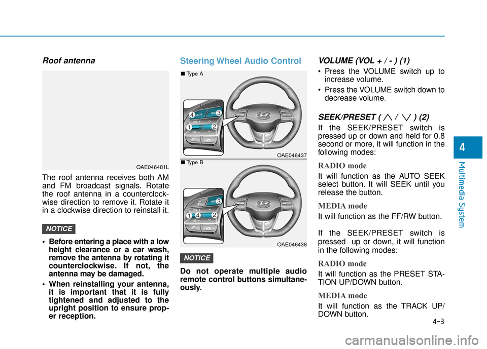
VOLUME (VOL + / - ) (1)
Press the VOLUME switch up to
increase volume.
Press the VOLUME switch down to decrease volume.
SEEK/PRESET ( / ) (2)
If the SEEK/PRESET switch is
pressed up or down and held for 0.8
second or more, it will function in the
following modes:
RADIO mode
It will function as the AUTO SEEK
select button. It will SEEK until you
release the button.
MEDIA mode
It will function as the FF/RW button.
If the SEEK/PRESET switch is
pressed up or down, it will function
in the following modes:
RADIO mode
It will function as the PRESET STA-
TION UP/DOWN button.
MEDIA mode
It will function as the TRACK UP/
DOWN button.
NOTICE
NOTICE
OAE046481L
OAE046437
OAE046438
■ Type A
■Type B
Page 260 of 541
![Hyundai Ioniq Electric 2018 Owners Manual 4-43
Multimedia System
4
System
Press the [SETUP]button on the
audio system ➟ Select [System].
Memory Information: View My Music memory usage.
Language: Change the user lan- guage.
Default: Reset Hyundai Ioniq Electric 2018 Owners Manual 4-43
Multimedia System
4
System
Press the [SETUP]button on the
audio system ➟ Select [System].
Memory Information: View My Music memory usage.
Language: Change the user lan- guage.
Default: Reset](/img/35/14904/w960_14904-259.png)
4-43
Multimedia System
4
System
Press the [SETUP]button on the
audio system ➟ Select [System].
Memory Information: View My Music memory usage.
Language: Change the user lan- guage.
Default: Reset the audio system.
System Information: At the System Information screen, Software version
information, updates are available.
- System Update: At the SystemInformation screen, insert the
USB memory with the latest file
downloaded, and then select the
[Update] to begin updating. The
system with then reboot auto-
matically.Information
• The system resets to the default val-ues, and all saved data and settings
are lost.
• This product needs supplemented software updates and additional
functions, which collectively may
take some time to complete, depend-
ing on the amount of data.
• If the Power is disconnected or the USB is removed during an update,
the data might be damaged. Please
wait until the update is complete
while engine is on.
Screen Saver
Set the information displayed when
the audio system is switched off or
the screen is turned off.
Press the [SETUP] button on the audio
system ➟Select [Screen Saver].
Analog: An analog clock is dis- played.
Digital: A digital clock is displayed.
None: No information is displayed.
Display Off
To prevent glare, the screen can be
turned off with the audio system in
operation.
Press the [SETUP]button on the
audio system ➟ Select [Display Off].
Information
Use ‘Screen Saver’ to set the informa-
tion to be displayed when the screen is
turned off.
i
i
Page 368 of 541
6-7
What to do in an emergency
6
4. Check for coolant leaking from theradiator, hoses or under the vehi-
cle. (If the air conditioning had
been in use, it is normal for cold
water to be draining from it when
you stop.)
5. If coolant is leaking out, stop the vehicle immediately and call the
nearest authorized HYUNDAI
dealer for assistance. 6. If you cannot find the cause of the
overheating, wait until the radiator
temperature has returned to nor-
mal. Then, if coolant has been
lost, carefully add coolant to the
reservoir to bring the fluid level in
the reservoir up to the halfway
mark.
7. Proceed with caution, keeping alert for further signs of overheat-
ing. If overheating happens again,
call an authorized HYUNDAI deal-
er for assistance.
While the vehicle is
running, keep hands,
clothing and tools
away from the mov-
ing parts such as the
cooling fan to prevent
serious injury.
WARNING
Serious loss of coolant indi-
cates a leak in the cooling sys-
tem and should be checked as
soon as possible by an author-
ized HYUNDAI dealer.
CAUTION
Your vehicle is
equipped with a pres-
surized coolant
reserve tank. NEVER
remove the coolant
reserve tank cap or the radiator
drain plug while the radiator is
HOT. Hot coolant and steam
may blow out under pressure,
causing serious injury.
Turn the vehicle off and wait
until the vehicle cools down.
Use extreme care when remov-
ing the coolant reserve tank
cap. Wrap a towel or thick rag
around it, and turn it counter-
clockwise slowly to release
some of the pressure from the
system. Step back while the
pressure is released.
When you are sure all the pres-
sure has been released, contin-
ue turning the cap counter-
clockwise to remove it.
WARNING
Page 383 of 541
6-22
What to do in an emergency
When towing your vehicle in an
emergency without wheel dollies:
1. While depressing the brake pedal shift to the N (Neutral) position
and turn the vehicle off. The
POWER button will be in the ACC
position.
2. Release the parking brake.
Failure to shift to N (Neutral) may
cause internal damage to the vehi-
cle.
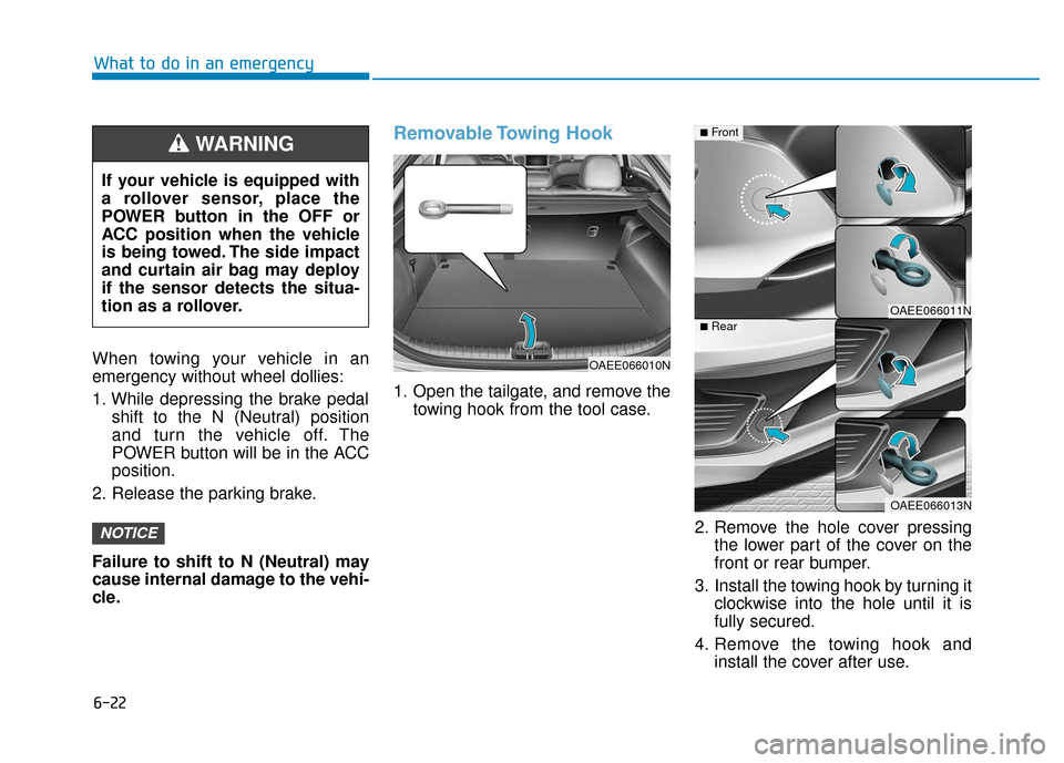
Removable Towing Hook
1. Open the tailgate, and remove the towing hook from the tool case.
2. Remove the hole cover pressingthe lower part of the cover on the
front or rear bumper.
3. Install the towing hook by turning it clockwise into the hole until it is
fully secured.
4. Remove the towing hook and install the cover after use.
NOTICE
If your vehicle is equipped with
a rollover sensor, place the
POWER button in the OFF or
ACC position when the vehicle
is being towed. The side impact
and curtain air bag may deploy
if the sensor detects the situa-
tion as a rollover.
WARNING
OAEE066010N
OAEE066011N
OAEE066013N
■Front
■Rear
Page 398 of 541
7-13
7
Maintenance
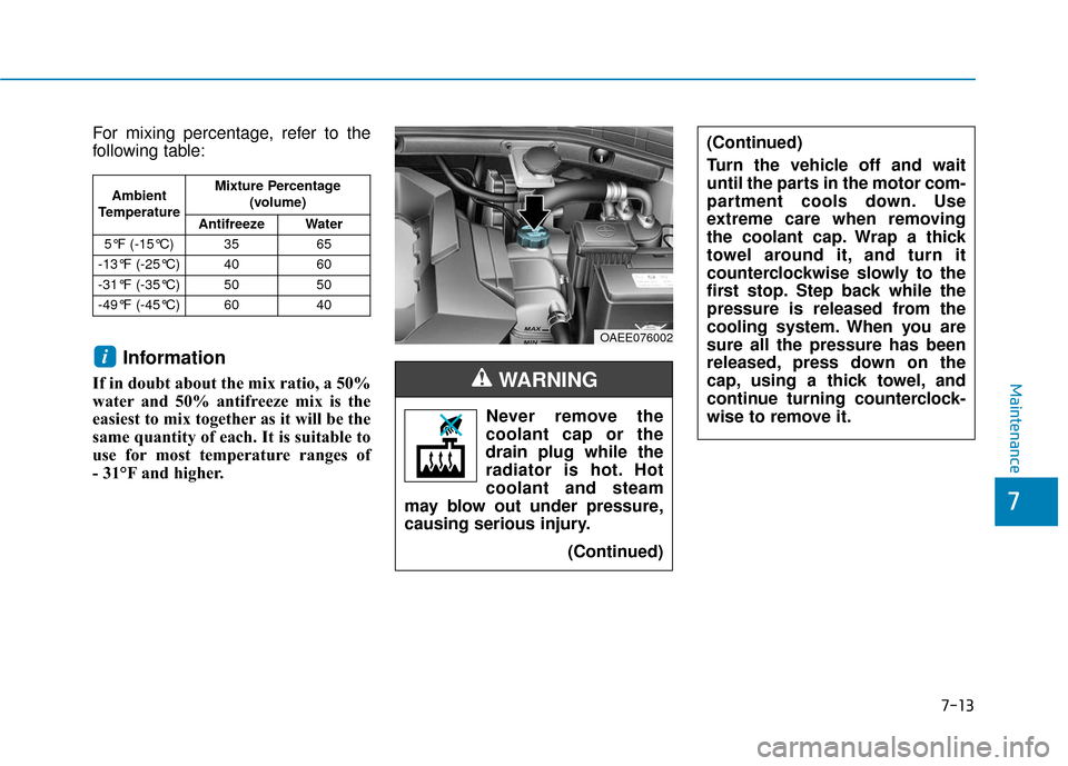
For mixing percentage, refer to the
following table:
Information
If in doubt about the mix ratio, a 50%
water and 50% antifreeze mix is the
easiest to mix together as it will be the
same quantity of each. It is suitable to
use for most temperature ranges of
- 31°F and higher.
i
Ambient
Temperature Mixture Percentage
(volume)
Antifreeze Water
5°F (-15°C) 35 65
-13°F (-25°C) 40 60
-31°F (-35°C) 50 50
-49°F (-45°C) 60 40
Never remove the
coolant cap or the
drain plug while the
radiator is hot. Hot
coolant and steam
may blow out under pressure,
causing serious injury.
(Continued)
WARNING
OAEE076002
(Continued)
Turn the vehicle off and wait
until the parts in the motor com-
partment cools down. Use
extreme care when removing
the coolant cap. Wrap a thick
towel around it, and turn it
counterclockwise slowly to the
first stop. Step back while the
pressure is released from the
cooling system. When you are
sure all the pressure has been
released, press down on the
cap, using a thick towel, and
continue turning counterclock-
wise to remove it.