fuse HYUNDAI IX20 2011 Owners Manual
[x] Cancel search | Manufacturer: HYUNDAI, Model Year: 2011, Model line: IX20, Model: HYUNDAI IX20 2011Pages: 420, PDF Size: 20.53 MB
Page 15 of 420
Your vehicle at a glance
2
2
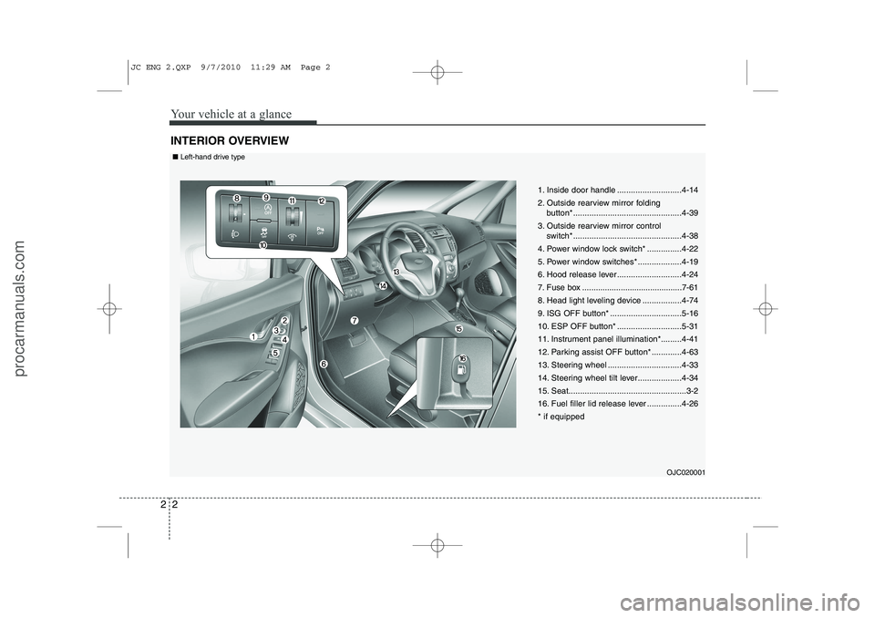
INTERIOR OVERVIEW
1. Inside door handle ............................4-14
2. Outside rearview mirror folding
button*...............................................4-39
3. Outside rearview mirror control switch* ...............................................4-38
4. Power window lock switch* ...............4-22
5. Power window switches* ...................4-19
6. Hood release lever ............................4-24
7. Fuse box ............................................7-61
8. Head light leveling device .................4-74
9. ISG OFF button* ...............................5-16
10. ESP OFF button* ............................5-31
11. Instrument panel illumination*.........4-41
12. Parking assist OFF button* .............4-63
13. Steering wheel ................................4-33
14. Steering wheel tilt lever...................4-34
15. Seat...................................................3-2
16. Fuel filler lid release lever ...............4-26* if equipped
OJC020001
■Left-hand drive type
JC ENG 2.QXP 9/7/2010 11:29 AM Page 2
procarmanuals.com
Page 16 of 420

23
Your vehicle at a glance
1. Inside door handle ............................4-14
2. Outside rearview mirror folding button*...............................................4-39
3. Outside rearview mirror control switch* ...............................................4-38
4. Power window lock switch* ...............4-22
5. Power window switches* ...................4-19
6. Hood release lever ............................4-24
7. Fuse box ............................................7-61
8. Head light leveling device .................4-74
9. ISG OFF button* ...............................5-16
10. ESP OFF button* ............................5-31
11. Instrument panel illumination*.........4-41
12. Parking assist OFF button* .............4-63
13. Steering wheel ................................4-33
14. Steering wheel tilt lever...................4-34
15. Seat...................................................3-2
16. Fuel filler lid release lever ...............4-26* if equipped
OJC020001R
■Right-hand drive type
JC ENG 2.QXP 9/7/2010 11:29 AM Page 3
procarmanuals.com
Page 19 of 420
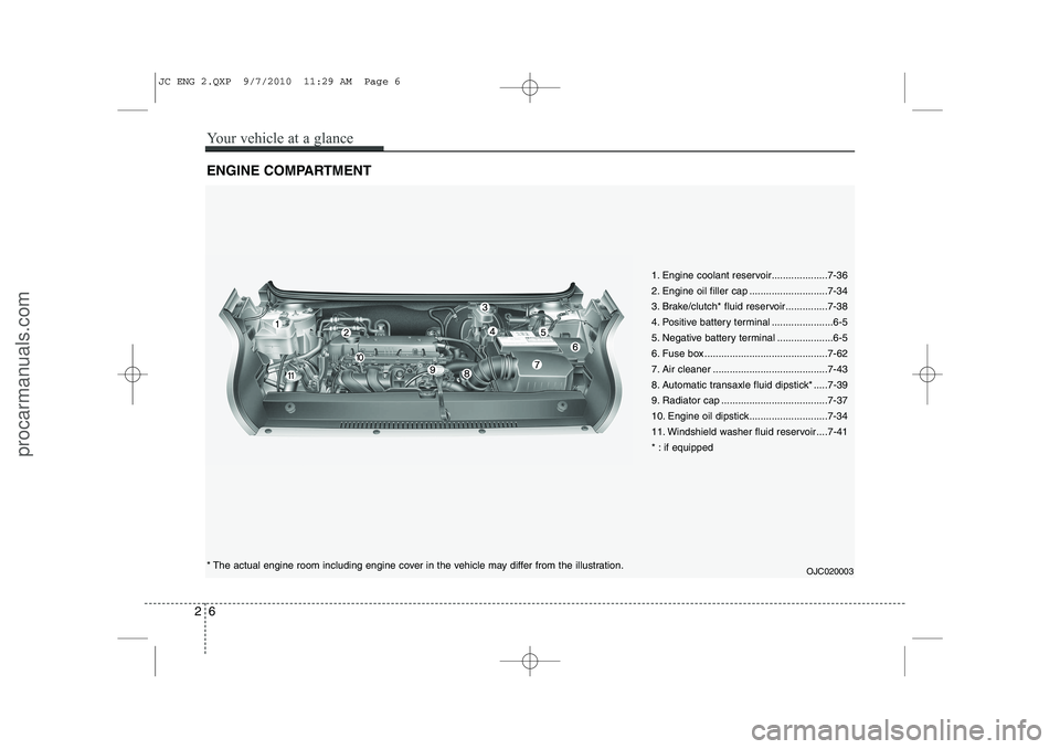
ENGINE COMPARTMENT
1. Engine coolant reservoir....................7-36
2. Engine oil filler cap ............................7-34
3. Brake/clutch* fluid reservoir...............7-38
4. Positive battery terminal ......................6-5
5. Negative battery terminal ....................6-5
6. Fuse box ............................................7-62
7. Air cleaner .........................................7-43
8. Automatic transaxle fluid dipstick* .....7-39
9. Radiator cap ......................................7-37
10. Engine oil dipstick............................7-34
11. Windshield washer fluid reservoir ....7-41
* : if equipped
* The actual engine room including engine cover in the vehicle may differ from the illustration.OJC020003
26
Your vehicle at a glance
JC ENG 2.QXP 9/7/2010 11:29 AM Page 6
procarmanuals.com
Page 63 of 420
Safety features of your vehicle
44
3
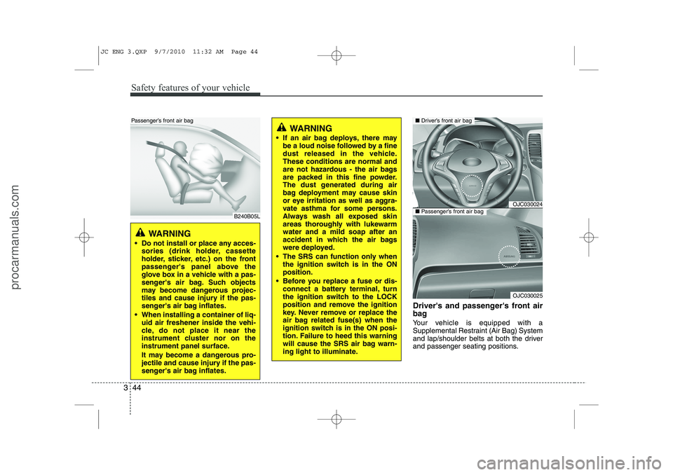
Driver's and passenger's front air
bag
Your vehicle is equipped with a
Supplemental Restraint (Air Bag) System
and lap/shoulder belts at both the driver
and passenger seating positions.
WARNING
If an air bag deploys, there may be a loud noise followed by a fine
dust released in the vehicle.These conditions are normal and
are not hazardous - the air bags
are packed in this fine powder.
The dust generated during air
bag deployment may cause skin
or eye irritation as well as aggra-
vate asthma for some persons.
Always wash all exposed skin
areas thoroughly with lukewarmwater and a mild soap after an
accident in which the air bags
were deployed.
The SRS can function only when the ignition switch is in the ONposition.
Before you replace a fuse or dis- connect a battery terminal, turn
the ignition switch to the LOCK
position and remove the ignition
key. Never remove or replace the
air bag related fuse(s) when the
ignition switch is in the ON posi-
tion. Failure to heed this warning
will cause the SRS air bag warn-
ing light to illuminate.
OJC030024
OJC030025
■Driver’s front air bag
■Passenger’s front air bag
WARNING
Do not install or place any acces- sories (drink holder, cassette
holder, sticker, etc.) on the front
passenger's panel above the
glove box in a vehicle with a pas-
senger's air bag. Such objects
may become dangerous projec-
tiles and cause injury if the pas-
senger's air bag inflates.
When installing a container of liq- uid air freshener inside the vehi-
cle, do not place it near the
instrument cluster nor on the
instrument panel surface.
It may become a dangerous pro-
jectile and cause injury if the pas-
senger's air bag inflates.
B240B05L
Passenger’s front air bag
JC ENG 3.QXP 9/7/2010 11:32 AM Page 44
procarmanuals.com
Page 100 of 420
Features of your vehicle
22
4
✽✽
NOTICE
The automatic reverse feature for the window is only active when the “auto
up” feature is used by fully pulling up
the switch. The automatic reverse fea-
ture will not operate if the window israised using the halfway position on the
power window switch.
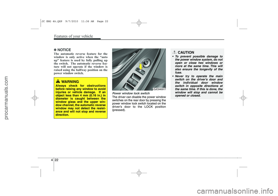
Power window lock switch
The driver can disable the power window
switches on the rear door by pressing the
power window lock switch located on the
driver’s door to the LOCK position(pressed).
CAUTION
To prevent possible damage to the power window system, do not
open or close two windows ormore at the same time. This willalso ensure the longevity of the fuse.
Never try to operate the main switch on the driver's door andthe individual door windowswitch in opposite directions at
the same time. If this is done, thewindow will stop and cannot be opened or closed.
WARNING
Always check for obstructions
before raising any window to avoid
injuries or vehicle damage. If anobject less than 4 mm (0.16 in.) indiameter is caught between the
window glass and the upper win-
dow channel, the automatic reverse
window may not detect the resist-
ance and will not stop and reversedirection.
OJC040017
JC ENG 4A.QXP 9/7/2010 11:36 AM Page 22
procarmanuals.com
Page 140 of 420
Features of your vehicle
62
4
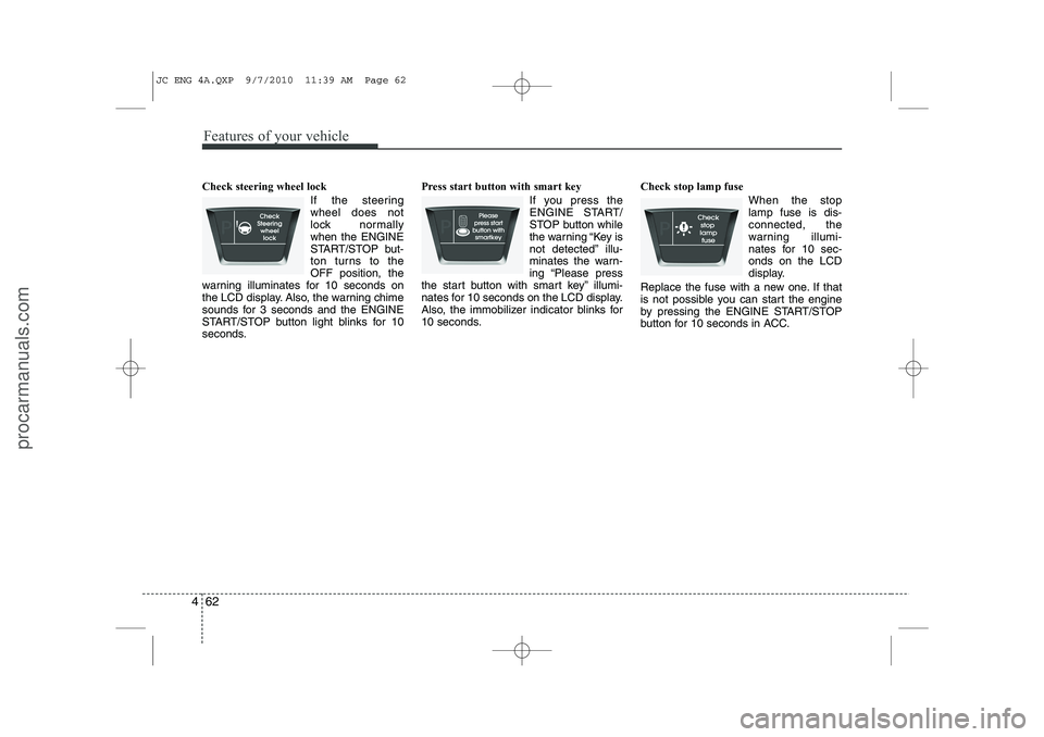
Check steering wheel lock
If the steering wheel does not
lock normallywhen the ENGINE
START/STOP but-
ton turns to theOFF position, the
warning illuminates for 10 seconds on
the LCD display. Also, the warning chime
sounds for 3 seconds and the ENGINE
START/STOP button light blinks for 10
seconds. Press start button with smart key
If you press the
ENGINE START/
STOP button while
the warning “Key is
not detected” illu-
minates the warn-
ing “Please press
the start button with smart key” illumi-
nates for 10 seconds on the LCD display.
Also, the immobilizer indicator blinks for
10 seconds. Check stop lamp fuse
When the stoplamp fuse is dis-connected, the
warning illumi-
nates for 10 sec-onds on the LCD
display.
Replace the fuse with a new one. If that
is not possible you can start the engine
by pressing the ENGINE START/STOP
button for 10 seconds in ACC.
JC ENG 4A.QXP 9/7/2010 11:39 AM Page 62
procarmanuals.com
Page 181 of 420
4 103
Features of your vehicle
INTERIOR FEATURES
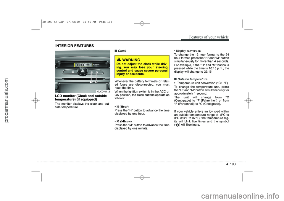
LCD monitor (Clock and outside temperature) (if equipped)
The monitor displays the clock and out-
side temperature.
■■Clock
Whenever the battery terminals or relat-
ed fuses are disconnected, you must
reset the time.
When the ignition switch is in the ACC or
ON position, the clock buttons operate as
follows:
Page 314 of 420
7
Engine compartment / 7-2 Maintenance services / 7-3
Owner maintenance / 7-5Scheduled maintenance service / 7-7Explanation of scheduled maintenance items / 7-30Engine oil / 7-34Engine coolant / 7-35Brake/clutch fluid / 7-38Automatic transaxle fluid / 7-39
Washer fluid / 7-41Parking brake / 7-41
Fuel filter / 7-42
Air cleaner / 7-43
Wiper blades / 7-44Battery / 7-47
Tires and wheels / 7-50Fuses / 7-60Light bulbs / 7-71
Appearance care / 7-79
Emission control system / 7-85
Maintenance
JC ENG 7.QXP 9/7/2010 11:58 AM Page 1
procarmanuals.com
Page 315 of 420
Maintenance
2
7
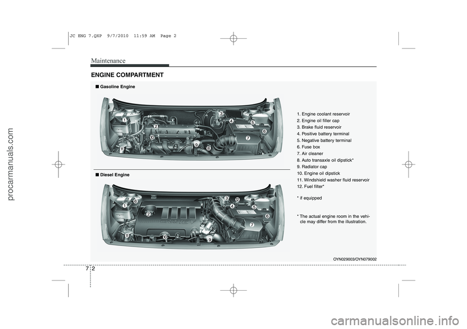
ENGINE COMPARTMENT
OYN029003/OYN079002
1. Engine coolant reservoir
2. Engine oil filler cap
3. Brake fluid reservoir
4. Positive battery terminal
5. Negative battery terminal
6. Fuse box
7. Air cleaner
8. Auto transaxle oil dipstick*
9. Radiator cap
10. Engine oil dipstick
11. Windshield washer fluid reservoir
12. Fuel filter* * if equipped
■■
Gasoline Engine
* The actual engine room in the vehi-
cle may differ from the illustration.
■■ Diesel Engine
JC ENG 7.QXP 9/7/2010 11:59 AM Page 2
procarmanuals.com
Page 373 of 420
Maintenance
60
7
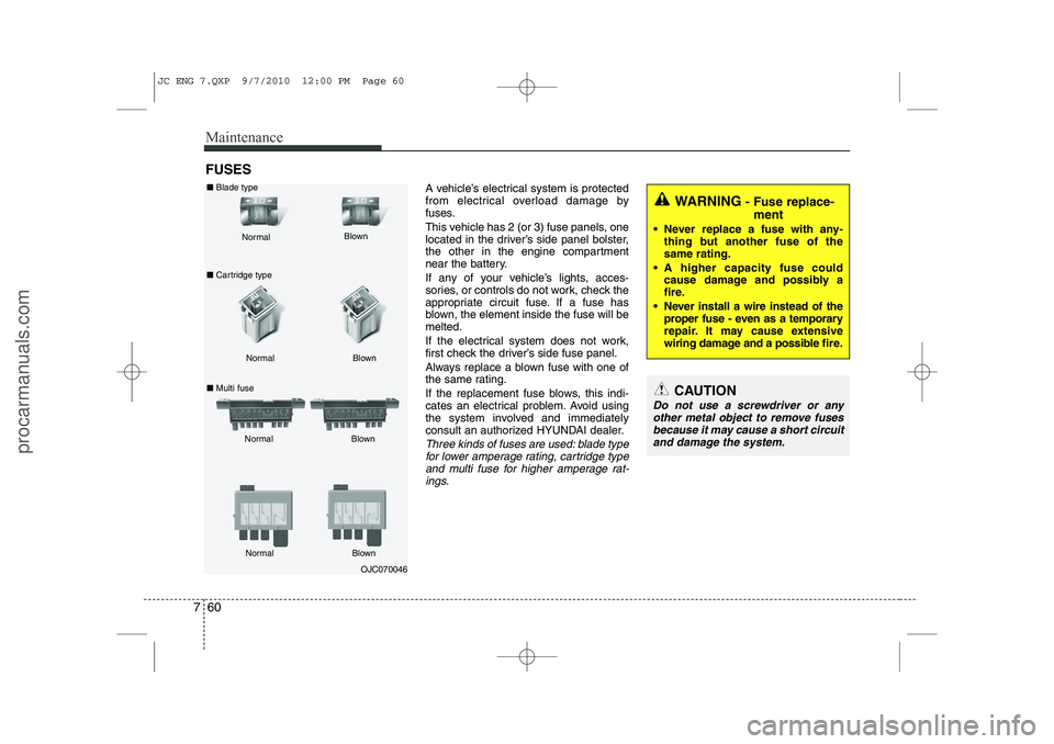
FUSES
A vehicle’s electrical system is protected
from electrical overload damage by
fuses.
This vehicle has 2 (or 3) fuse panels, one
located in the driver’s side panel bolster,
the other in the engine compartment
near the battery.
If any of your vehicle’s lights, acces-
sories, or controls do not work, check the
appropriate circuit fuse. If a fuse has
blown, the element inside the fuse will bemelted.
If the electrical system does not work,
first check the driver’s side fuse panel.
Always replace a blown fuse with one of
the same rating.
If the replacement fuse blows, this indi-
cates an electrical problem. Avoid using
the system involved and immediately
consult an authorized HYUNDAI dealer.
Three kinds of fuses are used: blade typefor lower amperage rating, cartridge type
and multi fuse for higher amperage rat- ings.
OJC070046
Normal
Normal
■ Cartridge type
■ Multi fuse Blown
Blown
Normal Blown
WARNING - Fuse replace-
ment
Never replace a fuse with any- thing but another fuse of the same rating.
A higher capacity fuse could cause damage and possibly a
fire.
Never install a wire instead of the proper fuse - even as a temporary
repair. It may cause extensive
wiring damage and a possible fire.
CAUTION
Do not use a screwdriver or any
other metal object to remove fusesbecause it may cause a short circuit and damage the system.
■ Blade type
Normal Blown
JC ENG 7.QXP 9/7/2010 12:00 PM Page 60
procarmanuals.com