instrument cluster HYUNDAI IX20 2015 Owners Manual
[x] Cancel search | Manufacturer: HYUNDAI, Model Year: 2015, Model line: IX20, Model: HYUNDAI IX20 2015Pages: 385, PDF Size: 13.67 MB
Page 7 of 385
1
How to use this manual / 1-2
Fuel requirements / 1-3
Vehicle run-inprocess / 1-6
Indicator symbols on the instrument cluster / 1-7
Introduction
procarmanuals.com
Page 13 of 385
17
Introduction
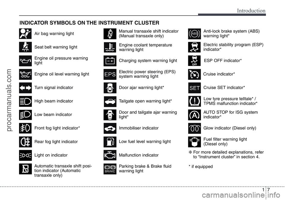
INDICATOR SYMBOLS ON THE INSTRUMENT CLUSTER
Engine coolant temperature
warning lightSeat belt warning light
High beam indicator
Turn signal indicator
Anti-lock brake system (ABS)
warning light*
Parking brake & Brake fluid
warning light
Malfunction indicator
Immobiliser indicatorGlow indicator (Diesel only)
Fuel filter warning light
(Diesel only) Tailgate open warning light*
Charging system warning light
Door ajar warning light*
Electric stability program (ESP)
indicator*
ESP OFF indicator*
Front fog light indicator*
Engine oil pressure warning
light
Electric power steering (EPS)
system warning light
Air bag warning light
Low tyre pressure telltale* /
TPMS malfunction indicator*
Rear fog light indicator
Cruise SET indicator*
AUTO STOP for ISG system
indicator*
Cruise indicator*
Light on indicator
Automatic transaxle shift posi-
tion indicator (Automatic
transaxle only)
Manual transaxle shift indicator
(Manual transaxle only)
* if equipped
Low fuel level warning light
Engine oil level warning light
Low beam indicatorDoor and tailgate ajar warning
light*
❈For more detailed explanations, refer
to “Instrument cluster” in section 4.
procarmanuals.com
Page 16 of 385
23
Your vehicle at a glance
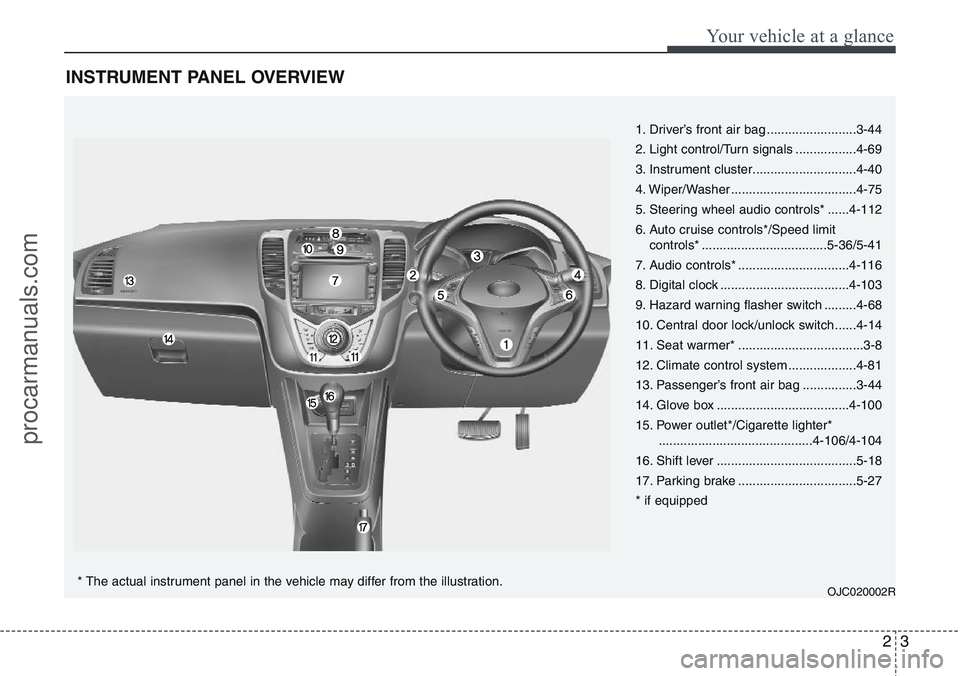
INSTRUMENT PANEL OVERVIEW
1. Driver’s front air bag .........................3-44
2. Light control/Turn signals .................4-69
3. Instrument cluster.............................4-40
4. Wiper/Washer ...................................4-75
5. Steering wheel audio controls* ......4-112
6. Auto cruise controls*/Speed limit
controls* ...................................5-36/5-41
7. Audio controls* ...............................4-116
8. Digital clock ....................................4-103
9. Hazard warning flasher switch .........4-68
10. Central door lock/unlock switch......4-14
11. Seat warmer* ...................................3-8
12. Climate control system ...................4-81
13. Passenger’s front air bag ...............3-44
14. Glove box .....................................4-100
15. Power outlet*/Cigarette lighter*
...........................................4-106/4-104
16. Shift lever .......................................5-18
17. Parking brake .................................5-27
* if equipped
OJC020002R* The actual instrument panel in the vehicle may differ from the illustration.
procarmanuals.com
Page 61 of 385
Safety features of your vehicle
44 3
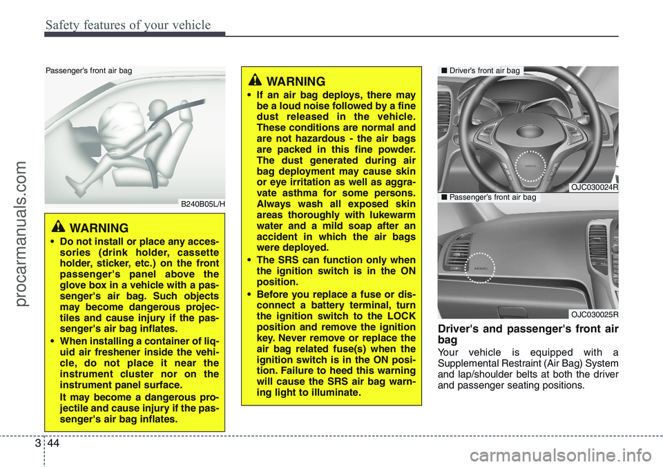
Driver's and passenger's front air
bag
Your vehicle is equipped with a
Supplemental Restraint (Air Bag) System
and lap/shoulder belts at both the driver
and passenger seating positions.
WARNING
• If an air bag deploys, there may
be a loud noise followed by a fine
dust released in the vehicle.
These conditions are normal and
are not hazardous - the air bags
are packed in this fine powder.
The dust generated during air
bag deployment may cause skin
or eye irritation as well as aggra-
vate asthma for some persons.
Always wash all exposed skin
areas thoroughly with lukewarm
water and a mild soap after an
accident in which the air bags
were deployed.
• The SRS can function only when
the ignition switch is in the ON
position.
• Before you replace a fuse or dis-
connect a battery terminal, turn
the ignition switch to the LOCK
position and remove the ignition
key. Never remove or replace the
air bag related fuse(s) when the
ignition switch is in the ON posi-
tion. Failure to heed this warning
will cause the SRS air bag warn-
ing light to illuminate.
OJC030024R
OJC030025R
■Driver’s front air bag
■Passenger’s front air bag
WARNING
• Do not install or place any acces-
sories (drink holder, cassette
holder, sticker, etc.) on the front
passenger's panel above the
glove box in a vehicle with a pas-
senger's air bag. Such objects
may become dangerous projec-
tiles and cause injury if the pas-
senger's air bag inflates.
• When installing a container of liq-
uid air freshener inside the vehi-
cle, do not place it near the
instrument cluster nor on the
instrument panel surface.
It may become a dangerous pro-
jectile and cause injury if the pas-
senger's air bag inflates.
B240B05L/H
Passenger’s front air bag
procarmanuals.com
Page 77 of 385
4
Keys / 4-2
Remote keyless entry / 4-5
Smart key / 4-8
Theft-alarm system / 4-11
Door locks / 4-13
Tailgate / 4-17
Windows / 4-19
Bonnet / 4-24
Fuel filler lid / 4-26
Panorama sunroof / 4-29
Steering wheel / 4-33
Mirrors / 4-35
Instrument cluster / 4-40
Rear parking assist system / 4-63
Rearview camera / 4-67
Hazard warning flasher / 4-68
Lighting / 4-69
Wipers and washers / 4-75
Interior light / 4-79
Defroster / 4-80
Manual climate control system / 4-81
Automatic climate control system / 4-90
Windscreen defrosting and defogging / 4-98
Storage compartment / 4-100
Interior features / 4-103
Audio system / 4-111
Features of your vehicle
procarmanuals.com
Page 116 of 385
Features of your vehicle
40 4
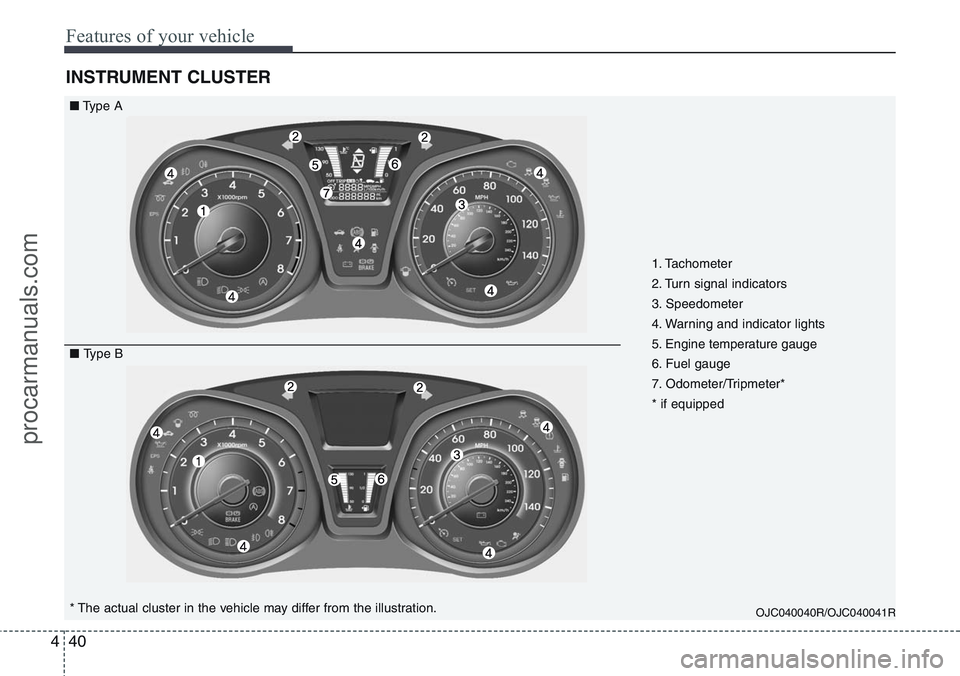
INSTRUMENT CLUSTER
OJC040040R/OJC040041R* The actual cluster in the vehicle may differ from the illustration.
■Type A
■ Type B1. Tachometer
2. Turn signal indicators
3. Speedometer
4. Warning and indicator lights
5. Engine temperature gauge
6. Fuel gauge
7. Odometer/Tripmeter*
* if equipped
procarmanuals.com
Page 117 of 385
441
Features of your vehicle
Instrument panel illumination
(if equipped)
Rotate the illumination control switch to
adjust the instrument panel illumination
intensity. For instrument cluster type A,
the vehicle’s parking lights or headlights
should be on to adjust the instrument
panel illumination.
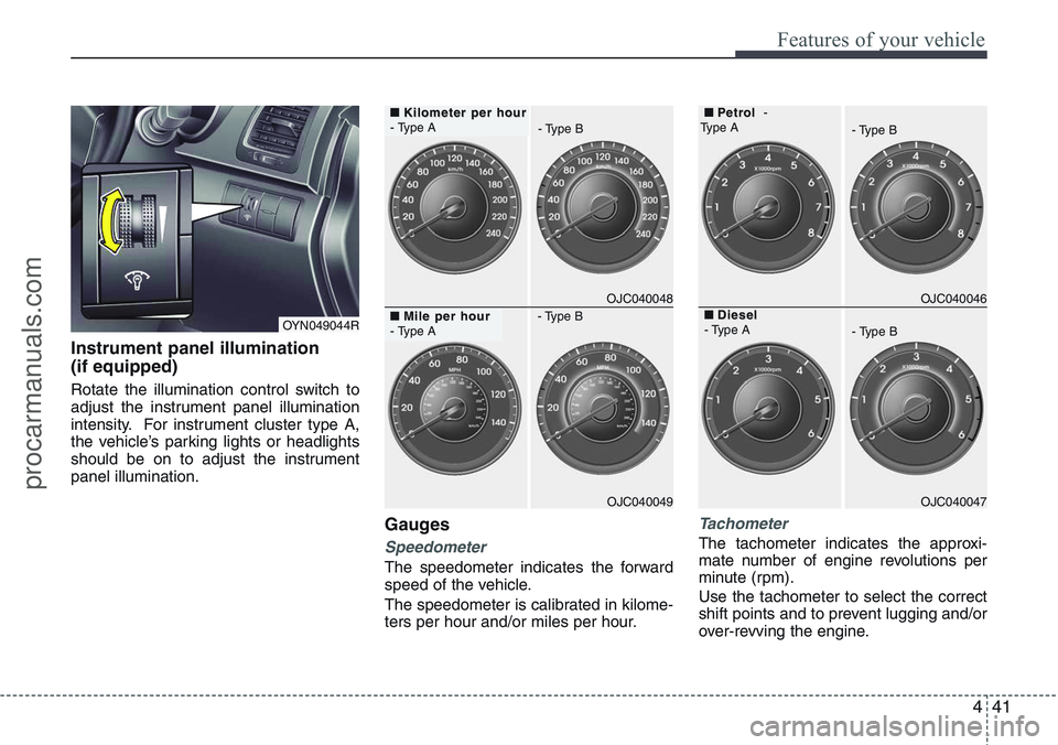
Gauges
Speedometer
The speedometer indicates the forward
speed of the vehicle.
The speedometer is calibrated in kilome-
ters per hour and/or miles per hour.
Tachometer
The tachometer indicates the approxi-
mate number of engine revolutions per
minute (rpm).
Use the tachometer to select the correct
shift points and to prevent lugging and/or
over-revving the engine.
OJC040048
OJC040049
■
Kilometer per hour Kilometer per hour
- Type A
■
Mile per hour Mile per hour
- Type AOJC040046
OJC040047
■
P P
etr etr
ol ol-
Type A
- Type B
■
Diesel Diesel
- Type A
- Type B - Type B
- Type B
OYN049044R
procarmanuals.com
Page 132 of 385
Features of your vehicle
56 4
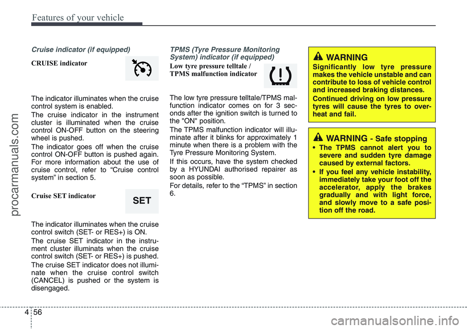
Cruise indicator (if equipped)
CRUISE indicator
The indicator illuminates when the cruise
control system is enabled.
The cruise indicator in the instrument
cluster is illuminated when the cruise
control ON-OFF button on the steering
wheel is pushed.
The indicator goes off when the cruise
control ON-OFF button is pushed again.
For more information about the use of
cruise control, refer to “Cruise control
system” in section 5.
Cruise SET indicator
The indicator illuminates when the cruise
control switch (SET- or RES+) is ON.
The cruise SET indicator in the instru-
ment cluster illuminats when the cruise
control switch (SET- or RES+) is pushed.
The cruise SET indicator does not illumi-
nate when the cruise control switch
(CANCEL) is pushed or the system is
disengaged.
TPMS (Tyre Pressure Monitoring
System) indicator (if equipped)
Low tyre pressure telltale /
TPMS malfunction indicator
The low tyre pressure telltale/TPMS mal-
function indicator comes on for 3 sec-
onds after the ignition switch is turned to
the "ON" position.
The TPMS malfunction indicator will illu-
minate after it blinks for approximately 1
minute when there is a problem with the
Tyre Pressure Monitoring System.
If this occurs, have the system checked
by a HYUNDAI authorised repairer as
soon as possible.
For details, refer to the “TPMS” in section
6.
SET
WARNING
Significantly low tyre pressure
makes the vehicle unstable and can
contribute to loss of vehicle control
and increased braking distances.
Continued driving on low pressure
tyres will cause the tyres to over-
heat and fail.
WARNING - Safe stopping
• The TPMS cannot alert you to
severe and sudden tyre damage
caused by external factors.
• If you feel any vehicle instability,
immediately take your foot off the
accelerator, apply the brakes
gradually and with light force,
and slowly move to a safe posi-
tion off the road.
procarmanuals.com
Page 230 of 385
Driving your vehicle
12 5
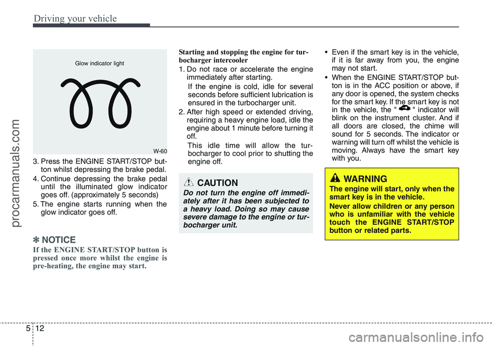
3. Press the ENGINE START/STOP but-
ton whilst depressing the brake pedal.
4. Continue depressing the brake pedal
until the illuminated glow indicator
goes off. (approximately 5 seconds)
5. The engine starts running when the
glow indicator goes off.
✽ NOTICE
If the ENGINE START/STOP button is
pressed once more whilst the engine is
pre-heating, the engine may start.
Starting and stopping the engine for tur-
bocharger intercooler
1. Do not race or accelerate the engine
immediately after starting.
If the engine is cold, idle for several
seconds before sufficient lubrication is
ensured in the turbocharger unit.
2. After high speed or extended driving,
requiring a heavy engine load, idle the
engine about 1 minute before turning it
off.
This idle time will allow the tur-
bocharger to cool prior to shutting the
engine off.• Even if the smart key is in the vehicle,
if it is far away from you, the engine
may not start.
• When the ENGINE START/STOP but-
ton is in the ACC position or above, if
any door is opened, the system checks
for the smart key. If the smart key is not
in the vehicle, the " " indicator will
blink on the instrument cluster. And if
all doors are closed, the chime will
sound for 5 seconds. The indicator or
warning will turn off whilst the vehicle is
moving. Always have the smart key
with you.
WARNING
The engine will start, only when the
smart key is in the vehicle.
Never allow children or any person
who is unfamiliar with the vehicle
touch the ENGINE START/STOP
button or related parts.
W-60 Glow indicator light
CAUTION
Do not turn the engine off immedi-
ately after it has been subjected to
a heavy load. Doing so may cause
severe damage to the engine or tur-
bocharger unit.
procarmanuals.com
Page 232 of 385
Driving your vehicle
14 5
Your vehicle may be equipped with the
ISG system, which reduces fuel con-
sumption by automatically shutting down
the engine, when the vehicle is at a
standstill. (For example : red light, stop
sign and traffic jam)
The engine starts automatically as soon
as the starting conditions are met.
The ISG system is ON whenever the
engine is running.
✽NOTICE
When the engine automatically starts by
the ISG system, some warning lights
(ABS, ESP, ESP OFF, EPS or Parking
brake warning light) may turn on for a
few seconds.
This happens because of low battery
voltage. It does not mean the system is
malfunctioning.Auto stop
To stop the engine in idle stop mode
1. Decrease the vehicle speed to less
than 3 mph (5 km/h).
2. Shift into N (Neutral) position.
3. Release the clutch pedal.
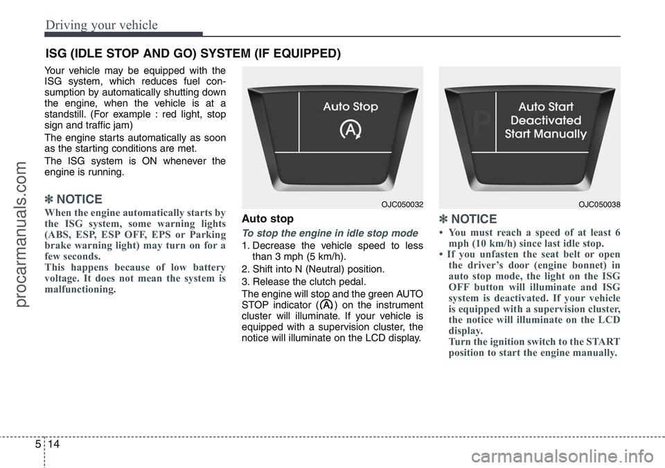
The engine will stop and the green AUTO
STOP indicator ( ) on the instrument
cluster will illuminate. If your vehicle is
equipped with a supervision cluster, the
notice will illuminate on the LCD display.
✽NOTICE
• You must reach a speed of at least 6
mph (10 km/h) since last idle stop.
• If you unfasten the seat belt or open
the driver’s door (engine bonnet) in
auto stop mode, the light on the ISG
OFF button will illuminate and ISG
system is deactivated. If your vehicle
is equipped with a supervision cluster,
the notice will illuminate on the LCD
display.
Turn the ignition switch to the START
position to start the engine manually.
ISG (IDLE STOP AND GO) SYSTEM (IF EQUIPPED)
OJC050032OJC050038
procarmanuals.com