sensor HYUNDAI IX35 2011 Owner's Manual
[x] Cancel search | Manufacturer: HYUNDAI, Model Year: 2011, Model line: IX35, Model: HYUNDAI IX35 2011Pages: 560, PDF Size: 28.31 MB
Page 340 of 560
Maintenance
20
7
Replace the filter according to the
Maintenance Schedule.
If the vehicle is operated in extremely
dusty or sandy areas, replace the ele-ment more often than the usual recom-
mended intervals.
CAUTION
Do not drive with the air cleaner removed; this will result in exces-
sive engine wear.
When removing the air cleaner fil- ter, be careful that dust or dirtdoes not enter the air intake, or
damage may result.
Use a HYUNDAI genuine part. Use of nongenuine part could damagethe air flow sensor or turbo charg-er.
EL UK 7.QXP 1/25/2010 10:02 AM Page 20
Page 364 of 560
Maintenance
44
7
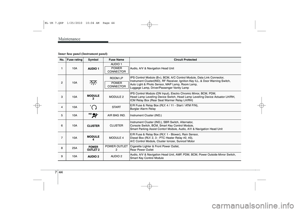
Inner fuse panel (Instrument panel)
No.Fuse ratingSymbolFuse NameCircuit Protected
110A
AUDIO 1
Audio, A/V & Navigation Head Unit
210A
ROOM LPIPS Control Module (B+), BCM, A/C Control Module, Data Link Connector,
Instrument Cluster(IND), RF Receiver, Ignition Key ILL. & Door Warning Switch,
Auto Light & Photo Sensor, MAP Lamp, Room Lamp,
Luggage Lamp, Driver/Passenger Vanity Lamp
310AMODULE 2IPS Control Module (ON Input), Electro Chromic Mirror, BCM, PDM,
Head Lamp Levelling Device Switch, Head Lamp Levelling Device Actuator LH/RH,
ICM Relay Box (Rear Seat Warmer Relay LH/RH)
410ASTARTE/R Fuse & Relay Box (RLY. 4 / 11 - Start / ATM P/N),
Burglar Alarm Relay
510AAIR BAG IND.Instrument Cluster (IND.)
610ACLUSTERInstrument Cluster (IND.), SBR Switch, Alternator,
Console Switch, BCM, Smart Key Control Module,
Smart Parking Assist Contorl Module, Audio, A/V & Navigation Head Unit
710AMODULE 4E/R Fuse & Relay Box (RLY. 1 - Blower), Rain Sensor,
Diesel Box (RLY. 2, 3 - PTC Heater Relay #2, #3),
A/C Control Module, Cluster Ionizer, Sunroof Motor
825APOWER OUTLET
2Cigarette Lighter & Front Power Outlet,
Rear Power Outlet
910AAUDIO 2Audio, A/V & Navigation Head Unit, AMP, PDM, BCM, Power Outside Mirror Switch,
Smart Key Control Module
POWER
CONNECTOR
POWER
CONNECTOR
EL UK 7.QXP 1/25/2010 10:04 AM Page 44
Page 365 of 560
745
Maintenance
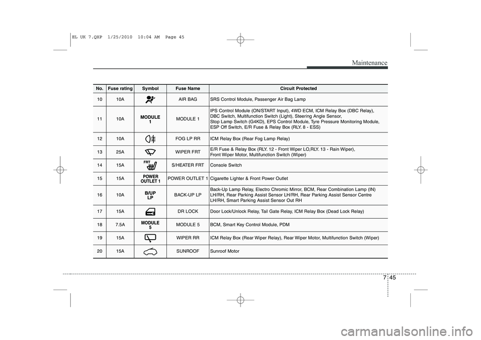
No.Fuse ratingSymbolFuse NameCircuit Protected
1010AAIR BAGSRS Control Module, Passenger Air Bag Lamp
1110AMODULE 1
IPS Control Module (ON/START Input), 4WD ECM, ICM Relay Box (DBC Relay),
DBC Switch, Multifunction Switch (Light), Steering Angle Sensor,
Stop Lamp Switch (G4KD), EPS Control Module, Tyre Pressure Monitoring Module,
ESP Off Switch, E/R Fuse & Relay Box (RLY. 8 - ESS)
1210AFOG LP RRICM Relay Box (Rear Fog Lamp Relay)
1325AWIPER FRTE/R Fuse & Relay Box (RLY. 12 - Front Wiper LO,RLY. 13 - Rain Wiper),
Front Wiper Motor, Multifunction Switch (Wiper)
1415AS/HEATER FRTConsole Switch
1515APOWER OUTLET 1Cigarette Lighter & Front Power Outlet
1610ABACK-UP LPBack-Up Lamp Relay, Electro Chromic Mirror, BCM, Rear Combination Lamp (IN)
LH/RH, Rear Parking Assist Sensor LH/RH, Rear Parking Assist Sensor Centre
LH/RH, Smart Parking Assist Sensor Out RH
1715ADR LOCKDoor Lock/Unlock Relay, Tail Gate Relay, ICM Relay Box (Dead Lock Relay)
187.5AMODULE 5BCM, Smart Key Control Module, PDM
1915AWIPER RRICM Relay Box (Rear Wiper Relay), Rear Wiper Motor, Multifunction Switch (Wiper)
2015ASUNROOFSunroof Motor
EL UK 7.QXP 1/25/2010 10:04 AM Page 45
Page 368 of 560
Maintenance
48
7
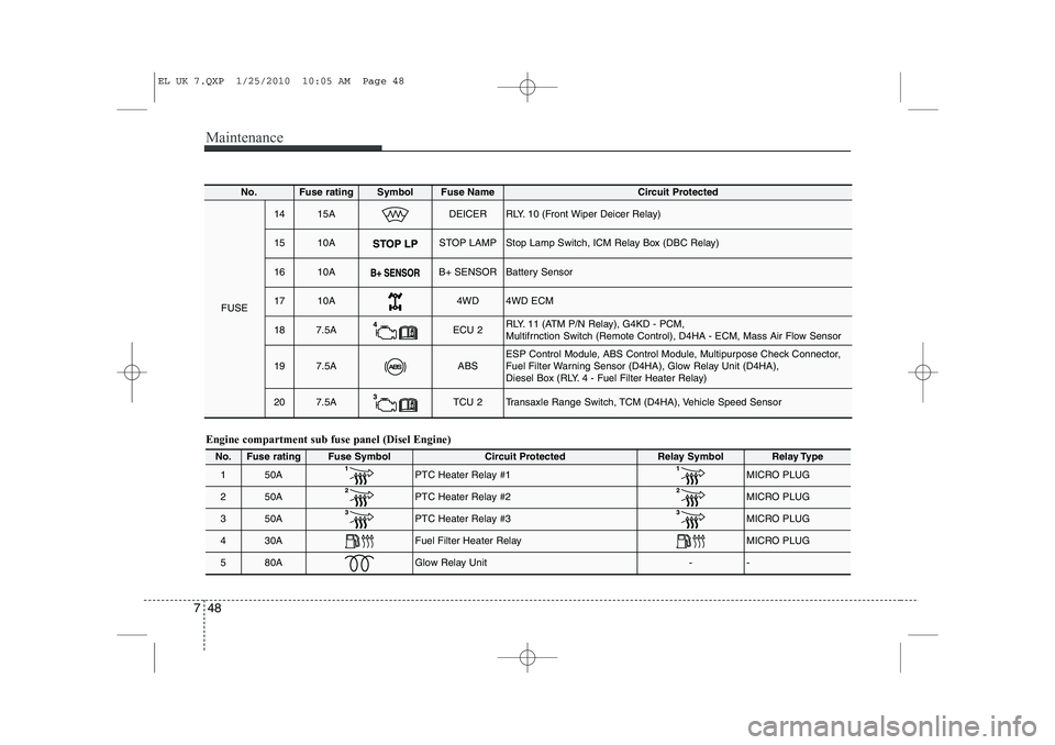
Engine compartment sub fuse panel (Disel Engine)
No.Fuse ratingFuse SymbolCircuit ProtectedRelay SymbolRelay Type
150APTC Heater Relay #1 MICRO PLUG
250APTC Heater Relay #2MICRO PLUG
350APTC Heater Relay #3 MICRO PLUG
430AFuel Filter Heater Relay MICRO PLUG
580AGlow Relay Unit--
No.Fuse ratingSymbolFuse Name Circuit Protected
FUSE
1415ADEICERRLY. 10 (Front Wiper Deicer Relay)
1510ASTOP LAMPStop Lamp Switch, ICM Relay Box (DBC Relay)
1610AB+ SENSORBattery Sensor
1710A4WD4WD ECM
187.5AECU 2RLY. 11 (ATM P/N Relay), G4KD - PCM,
Multifrnction Switch (Remote Control), D4HA - ECM, Mass Air Flow Sensor
197.5AABSESP Control Module, ABS Control Module, Multipurpose Check Connector,
Fuel Filter Warning Sensor (D4HA), Glow Relay Unit (D4HA),
Diesel Box (RLY. 4 - Fuel Filter Heater Relay)
207.5ATCU 2Transaxle Range Switch, TCM (D4HA), Vehicle Speed Sensor
EL UK 7.QXP 1/25/2010 10:05 AM Page 48
Page 447 of 560
435
Features of your vehicle
Inside rearview mirror
Adjust the rearview mirror to centre on
the view through the rear window. Make
this adjustment before you start driving.
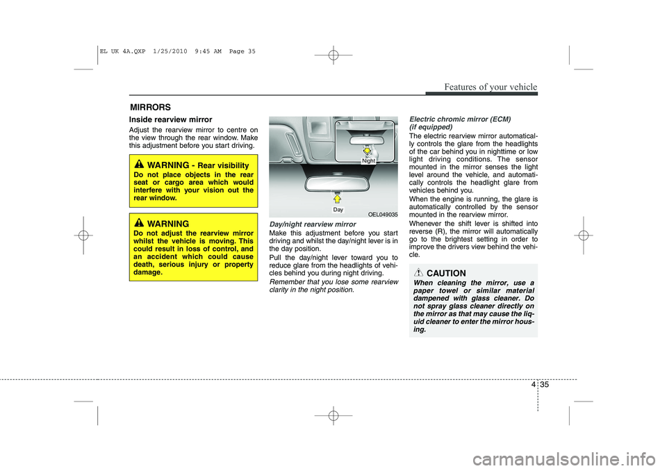
Day/night rearview mirror
Make this adjustment before you start
driving and whilst the day/night lever is in
the day position.
Pull the day/night lever toward you to
reduce glare from the headlights of vehi-
cles behind you during night driving.
Remember that you lose some rearviewclarity in the night position.
Electric chromic mirror (ECM) (if equipped)
The electric rearview mirror automatical- ly controls the glare from the headlights
of the car behind you in nighttime or low
light driving conditions. The sensormounted in the mirror senses the light
level around the vehicle, and automati-cally controls the headlight glare from
vehicles behind you.
When the engine is running, the glare is
automatically controlled by the sensor
mounted in the rearview mirror.
Whenever the shift lever is shifted into
reverse (R), the mirror will automatically
go to the brightest setting in order to
improve the drivers view behind the vehi-
cle.
MIRRORS
WARNING -
Rear visibility
Do not place objects in the rear
seat or cargo area which would
interfere with your vision out the
rear window.
OEL049035
CAUTION
When cleaning the mirror, use a paper towel or similar materialdampened with glass cleaner. Do not spray glass cleaner directly on
the mirror as that may cause the liq- uid cleaner to enter the mirror hous-ing.
Day
Night
WARNING
Do not adjust the rearview mirror
whilst the vehicle is moving. This
could result in loss of control, and
an accident which could cause
death, serious injury or property
damage.
EL UK 4A.QXP 1/25/2010 9:45 AM Page 35
Page 448 of 560
Features of your vehicle
36
4
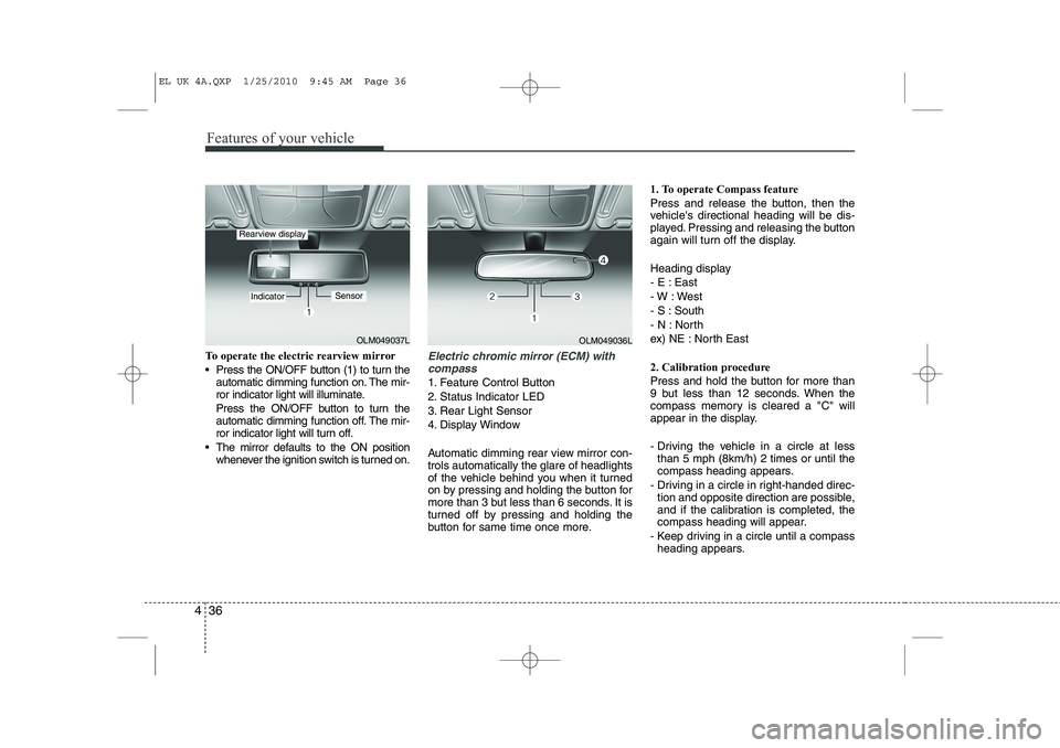
To operate the electric rearview mirror
Press the ON/OFF button (1) to turn the
automatic dimming function on. The mir-
ror indicator light will illuminate.
Press the ON/OFF button to turn the
automatic dimming function off. The mir-
ror indicator light will turn off.
The mirror defaults to the ON position whenever the ignition switch is turned on.Electric chromic mirror (ECM) with
compass
1. Feature Control Button
2. Status Indicator LED
3. Rear Light Sensor
4. Display Window
Automatic dimming rear view mirror con- trols automatically the glare of headlights
of the vehicle behind you when it turned
on by pressing and holding the button for
more than 3 but less than 6 seconds. It is
turned off by pressing and holding the
button for same time once more. 1. To operate Compass feature
Press and release the button, then the
vehicle's directional heading will be dis-
played. Pressing and releasing the button
again will turn off the display.
Heading display
- E : East
- W : West
- S : South
- N : North
ex) NE : North East
2. Calibration procedure
Press and hold the button for more than
9 but less than 12 seconds. When the
compass memory is cleared a "C" will
appear in the display.
- Driving the vehicle in a circle at less
than 5 mph (8km/h) 2 times or until the
compass heading appears.
- Driving in a circle in right-handed direc- tion and opposite direction are possible,
and if the calibration is completed, the
compass heading will appear.
- Keep driving in a circle until a compass heading appears.
OLM049037L
IndicatorSensor
Rearview display
OLM049036L
EL UK 4A.QXP 1/25/2010 9:45 AM Page 36
Page 479 of 560
467
Features of your vehicle
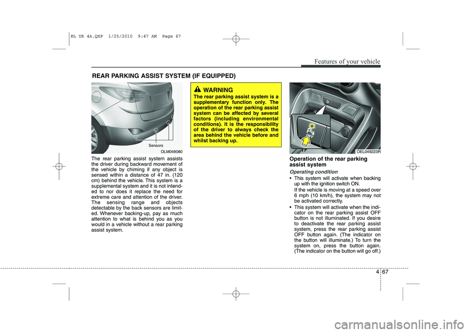
The rear parking assist system assists
the driver during backward movement of
the vehicle by chiming if any object is
sensed within a distance of 47 in. (120
cm) behind the vehicle. This system is asupplemental system and it is not intend-
ed to nor does it replace the need for
extreme care and attention of the driver.
The sensing range and objects
detectable by the back sensors are limit-
ed. Whenever backing-up, pay as much
attention to what is behind you as you
would in a vehicle without a rear parkingassist system.Operation of the rear parking assist system
Operating condition
This system will activate when backing
up with the ignition switch ON.
If the vehicle is moving at a speed over
6 mph (10 km/h), the system may not
be activated correctly.
This system will activate when the indi- cator on the rear parking assist OFF
button is not illuminated. If you desire
to deactivate the rear parking assist
system, press the rear parking assist
OFF button again. (The indicator on
the button will illuminate.) To turn the
system on, press the button again.
(The indicator on the button will go off.)
REAR PARKING ASSIST SYSTEM (IF EQUIPPED)
OLM049080
WARNING
The rear parking assist system is a supplementary function only. Theoperation of the rear parking assistsystem can be affected by severalfactors (including environmentalconditions). It is the responsibilityof the driver to always check thearea behind the vehicle before andwhilst backing up.
Sensors
OEL049223R
EL UK 4A.QXP 1/25/2010 9:47 AM Page 67
Page 480 of 560
Features of your vehicle
68
4
The sensing distance whilst the rear
parking assist system is in operation is
approximately 47 in. (120 cm).
When more than two objects are sensed at the same time, the closest
one will be recognized first.
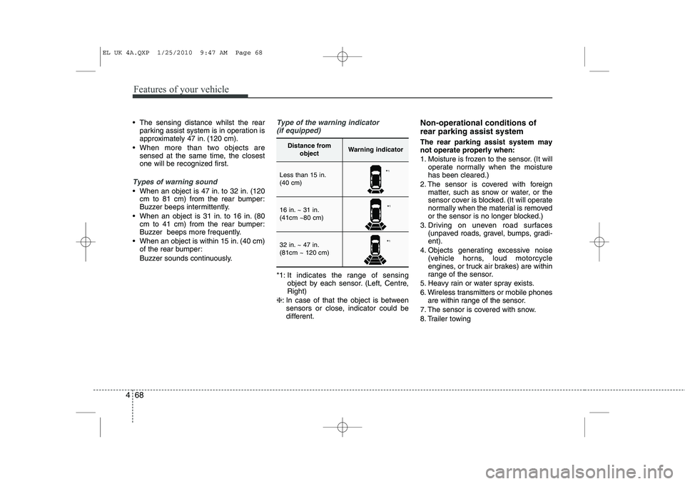
Types of warning sound
When an object is 47 in. to 32 in. (120cm to 81 cm) from the rear bumper:
Buzzer beeps intermittently.
When an object is 31 in. to 16 in. (80 cm to 41 cm) from the rear bumper:
Buzzer beeps more frequently.
When an object is within 15 in. (40 cm) of the rear bumper:
Buzzer sounds continuously.
Type of the warning indicator
(if equipped)
*1: It indicates the range of sensing object by each sensor. (Left, Centre, Right)
❈ : In case of that the object is between
sensors or close, indicator could be
different. Non-operational conditions of rear parking assist system The rear parking assist system may not operate properly when:
1. Moisture is frozen to the sensor. (It will
operate normally when the moisture has been cleared.)
2. The sensor is covered with foreign matter, such as snow or water, or the
sensor cover is blocked. (It will operate
normally when the material is removed
or the sensor is no longer blocked.)
3. Driving on uneven road surfaces (unpaved roads, gravel, bumps, gradi-ent).
4. Objects generating excessive noise (vehicle horns, loud motorcycle
engines, or truck air brakes) are within
range of the sensor.
5. Heavy rain or water spray exists.
6. Wireless transmitters or mobile phones are within range of the sensor.
7. The sensor is covered with snow.
8. Trailer towing
Distance from objectWarning indicator
Less than 15 in. (40 cm)
16 in. ~ 31 in. (41cm ~80 cm)
32 in. ~ 47 in. (81cm ~ 120 cm)
*1
* 1
* 1
EL UK 4A.QXP 1/25/2010 9:47 AM Page 68
Page 481 of 560
469
Features of your vehicle
The detecting range may decrease when:
1. The sensor is stained with foreign mat-ter such as snow or water. (The sens-
ing range will return to normal when
removed.)
2. Outside air temperature is extremely hot or cold.
The following objects may not be rec-ognized by the sensor:
1. Sharp or slim objects such as ropes, chains or small poles.
2. Objects which tend to absorb the sen- sor frequency such as clothes, spongy
material or snow.
3. Undetectable objects smaller than 40 in. (1 m) in height and narrower than 6 in.
(14 cm) in diameter. Rear parking assist system pre- cautions
The rear parking assist system may
not sound sequentially depending on the speed and shapes of the objectsdetected.
The rear parking assist system may malfunction if the vehicle bumperheight or sensor installation has been
modified or damaged. Any non-factory
installed equipment or accessories
may also interfere with the sensor per-
formance.
The sensor may not recognize objects less than 15 in. (40 cm) from the sen-
sor, or it may sense an incorrect dis-
tance. Use caution.
When the sensor is frozen or stained with snow, dirt, or water, the sensor
may be inoperative until the stains are
removed using a soft cloth.
Do not push, scratch or strike the sen- sor. Sensor damage could occur.✽✽ NOTICE
This system can only sense objects with- in the range and location of the sensors;
It can not detect objects in other areas
where sensors are not installed. Also,
small or slim objects, such as poles orobjects located between sensors may notbe detected by the sensors.Always visually check behind the vehi-cle when backing up.
Be sure to inform any drivers of the
vehicle that may be unfamiliar with the
system regarding the systems capabili-ties and limitations.
WARNING
Pay close attention when the vehi- cle is driven close to objects on theroad, particularly pedestrians, andespecially children. Be aware thatsome objects may not be detectedby the sensors, due to the object’sdistance, size or material, all ofwhich can limit the effectiveness ofthe sensor. Always perform a visu-al inspection to make sure the vehi-cle is clear of all obstructionsbefore moving the vehicle in anydirection.
EL UK 4A.QXP 1/25/2010 9:47 AM Page 69
Page 486 of 560
Features of your vehicle
74
4
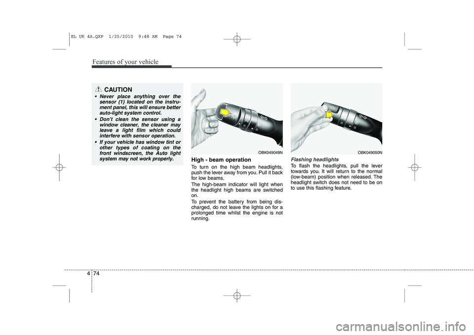
High - beam operation
To turn on the high beam headlights,
push the lever away from you. Pull it back
for low beams. The high-beam indicator will light when
the headlight high beams are switchedon.
To prevent the battery from being dis-
charged, do not leave the lights on for aprolonged time whilst the engine is not
running.Flashing headlights
To flash the headlights, pull the lever
towards you. It will return to the normal
(low-beam) position when released. The
headlight switch does not need to be on
to use this flashing feature.
OBK049049NOBK049050N
CAUTION
Never place anything over the
sensor (1) located on the instru-
ment panel, this will ensure betterauto-light system control.
Don’t clean the sensor using a window cleaner, the cleaner may
leave a light film which could interfere with sensor operation.
If your vehicle has window tint or other types of coating on thefront windscreen, the Auto light
system may not work properly.
EL UK 4A.QXP 1/25/2010 9:48 AM Page 74