power steering HYUNDAI IX35 2014 Owners Manual
[x] Cancel search | Manufacturer: HYUNDAI, Model Year: 2014, Model line: IX35, Model: HYUNDAI IX35 2014Pages: 1534, PDF Size: 39.76 MB
Page 7 of 1534
17
Introduction
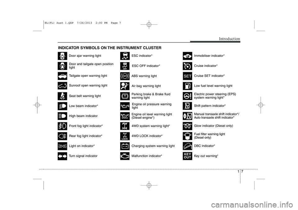
INDICATOR SYMBOLS ON THE INSTRUMENT CLUSTER
Engine oil pressure warning light
Seat belt warning light
Door and tailgate open position light
High beam indicator
Light on indicator*
Turn signal indicator
ABS warning light
Parking brake & Brake fluid
warning light
4WD system warning light* 4WD LOCK indicator*
Malfunction indicator*
Air bag warning light
Cruise SET indicator*
Low fuel level warning light
Charging system warning light
Door ajar warning light
Glow indicator (Diesel only)
Fuel filter warning light (Diesel only)
Cruise indicator*
ESC indicator*
ESC OFF indicator*
Immobiliser indicator*
Shift pattern indicator*
Front fog light indicator*
Rear fog light indicator*
Low beam indicator*
Electric power steering (EPS)
system warning light*
Key out warning*
KEY
OUT
DBC indicator*
Tailgate open warning light
Sunroof open warning light
Engine oil level warning light (Diesel engine*)Manual transaxle shift indicator*/
Auto transaxle shift indicator*
EL(FL) Aust 1.QXP 7/26/2013 2:00 PM Page 7
Page 10 of 1534
Your vehicle at a glance
2
2
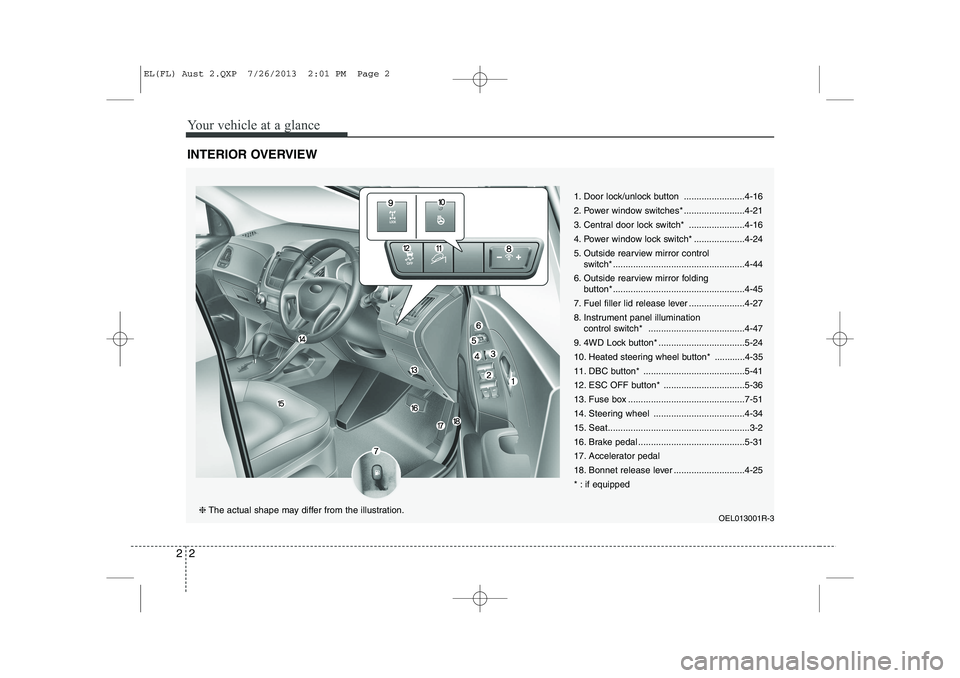
INTERIOR OVERVIEW
1. Door lock/unlock button ........................4-16
2. Power window switches* ........................4-21
3. Central door lock switch* ......................4-16
4. Power window lock switch* ....................4-24
5. Outside rearview mirror control
switch* ....................................................4-44
6. Outside rearview mirror folding button* ....................................................4-45
7. Fuel filler lid release lever ......................4-27
8. Instrument panel illumination control switch* ......................................4-47
9. 4WD Lock button* ..................................5-24
10. Heated steering wheel button* ............4-35
11. DBC button* ........................................5-41
12. ESC OFF button* ................................5-36
13. Fuse box ..............................................7-51
14. Steering wheel ....................................4-34
15. Seat........................................................3-2
16. Brake pedal ..........................................5-31
17. Accelerator pedal
18. Bonnet release lever ............................4-25
* : if equipped
OEL013001R-3
❈The actual shape may differ from the illustration.
EL(FL) Aust 2.QXP 7/26/2013 2:01 PM Page 2
Page 11 of 1534
23
Your vehicle at a glance
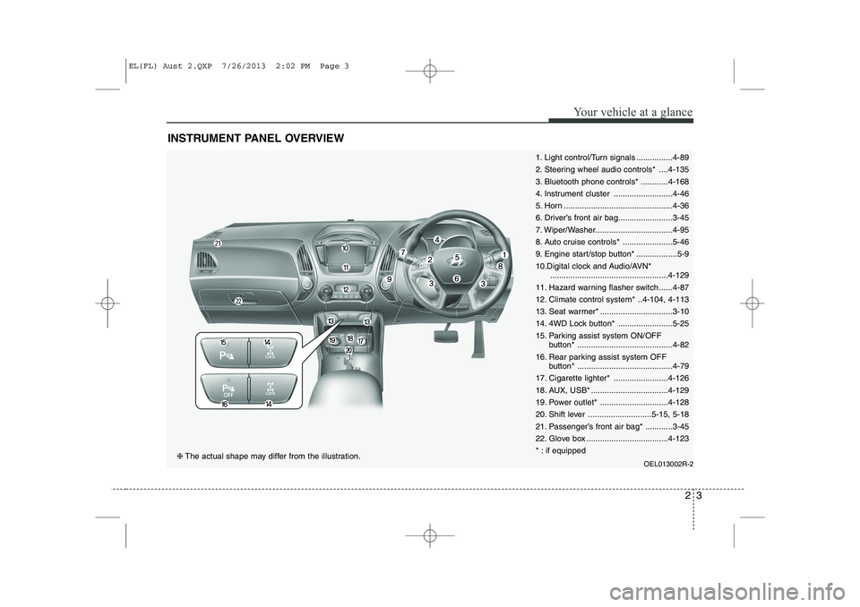
INSTRUMENT PANEL OVERVIEW
1. Light control/Turn signals ................4-89
2. Steering wheel audio controls* ....4-135
3. Bluetooth phone controls* ............4-168
4. Instrument cluster ..........................4-46
5. Horn ................................................4-36
6. Driver’s front air bag........................3-45
7. Wiper/Washer..................................4-95
8. Auto cruise controls* ......................5-46
9. Engine start/stop button* ..................5-9
10.Digital clock and Audio/AVN*....................................................4-129
11. Hazard warning flasher switch ......4-87
12. Climate control system* ..4-104, 4-113
13. Seat warmer* ................................3-10
14. 4WD Lock button* ........................5-25
15. Parking assist system ON/OFF button* ..........................................4-82
16. Rear parking assist system OFF button* ..........................................4-79
17. Cigarette lighter* ........................4-126
18. AUX, USB* ..................................4-129
19. Power outlet* ..............................4-128
20. Shift lever ............................5-15, 5-18
21. Passenger’s front air bag* ............3-45
22. Glove box ....................................4-123
* : if equipped
OEL013002R-2
❈The actual shape may differ from the illustration.
EL(FL) Aust 2.QXP 7/26/2013 2:02 PM Page 3
Page 19 of 1534
Safety features of your vehicle
6
3
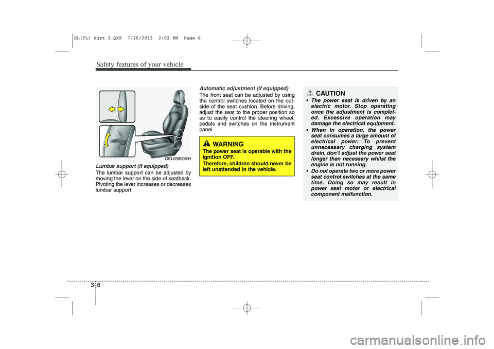
Lumbar support (if equipped)
The lumbar support can be adjusted by
moving the lever on the side of seatback.
Pivoting the lever increases or decreases
lumbar support.
Automatic adjustment (if equipped)
The front seat can be adjusted by using
the control switches located on the out-
side of the seat cushion. Before driving,adjust the seat to the proper position so
as to easily control the steering wheel,
pedals and switches on the instrumentpanel.
WARNING
The power seat is operable with the
ignition OFF.
Therefore, children should never be
left unattended in the vehicle.
CAUTION
The power seat is driven by an electric motor. Stop operating
once the adjustment is complet- ed. Excessive operation maydamage the electrical equipment.
When in operation, the power seat consumes a large amount ofelectrical power. To prevent unnecessary charging systemdrain, don’t adjust the power seat
longer than necessary whilst the engine is not running.
Do not operate two or more power seat control switches at the same
time. Doing so may result in power seat motor or electricalcomponent malfunction.
OEL039005/H
EL(FL) Aust 3.QXP 7/26/2013 2:03 PM Page 6
Page 106 of 1534
Features of your vehicle
34
4
Electric power steering
Power steering uses the motor to assist
you in steering the vehicle. If the engine
is off or if the power steering system
becomes inoperative, the vehicle may
still be steered, but it will require
increased steering effort.
The motor driven power steering is con-
trolled by the power steering control unit
which senses the steering wheel torque
and vehicle speed to command the
motor.
The steering wheel becomes heavier as
the vehicle’s speed increases and
becomes lighter as the vehicle’s speed
decreases for better control of the steer-ing wheel.
Should you notice any change in the
effort required to steering during normal
vehicle operation, we recommend that
the system be checked by an authorised
HYUNDAI dealer.✽✽
NOTICE
The following symptoms may occur dur- ing normal vehicle operation:
Page 110 of 1534
Features of your vehicle
38
4
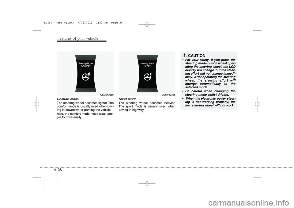
Comfort mode
The steering wheel becomes lighter. The
comfort mode is usually used when driv-
ing in downtown or parking the vehicle.
Also, the comfort mode helps weak peo-
ple to drive easily.
Sport mode
The steering wheel becomes heavier.
The sport mode is usually used when
driving in highway.
OLM043355OLM043356
CAUTION
For your safety, if you press the
steering mode button whilst oper-
ating the steering wheel, the LCD display will change, but the steer-ing effort will not change immedi-ately. After operating the steering
wheel, the steering effort willchange automatically to the selected mode.
Be careful when changing the steering mode whilst driving.
When the electronic power steer- ing is not working properly, theflex steering wheel will not work.
EL(FL) Aust 4a.QXP 7/26/2013 2:33 PM Page 38
Page 150 of 1534
Features of your vehicle
78
4
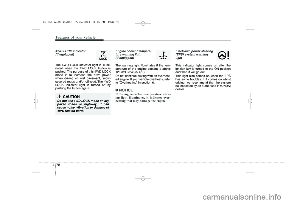
4WD LOCK indicator
(if equipped)
The 4WD LOCK indicator light is illumi-
nated when the 4WD LOCK button is
pushed. The purpose of this 4WD LOCK
mode is to increase the drive power
when driving on wet pavement, snow-
covered roads and/or off-road. The 4WD
LOCK indicator light is turned off by
pushing the button again.
Engine coolant tempera-ture warning light (if equipped)
The warning light illuminates if the tem-
perature of the engine coolant is above120±3°C (248±5.4°F).
Do not continue driving with an overheat-
ed engine. If your vehicle overheats, refer
to “Overheating” in section 6.
✽✽ NOTICE
If the engine coolant temperature warn- ing light illuminates, it indicates over-heating that may damage the engine.
Electronic power steering (EPS) system warninglight
This indicator light comes on after the
ignition key is turned to the ON positionand then it will go out. This light also comes on when the EPS
has some troubles. If it comes on whilst
driving, we recommend that the system
be inspected by an authorised HYUNDAI
dealer.
CAUTION
Do not use 4WD LOCK mode on dry paved roads or highway, it cancause noise, vibration or damage of
4WD related parts.
EL(FL) Aust 4a.QXP 7/26/2013 2:35 PM Page 78
Page 201 of 1534
4 129
Features of your vehicle
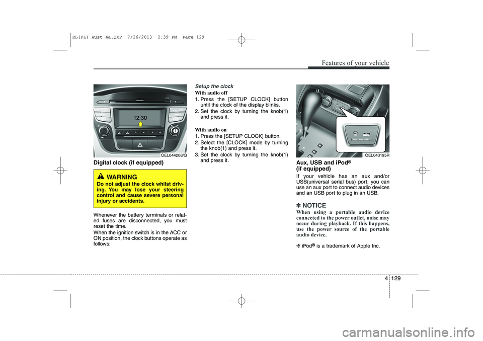
Digital clock (if equipped)
Whenever the battery terminals or relat-
ed fuses are disconnected, you must
reset the time.
When the ignition switch is in the ACC or
ON position, the clock buttons operate as
follows:
Setup the clock
With audio off
1. Press the [SETUP CLOCK] buttonuntil the clock of the display blinks.
2. Set the clock by turning the knob(1) and press it.
With audio on
1. Press the [SETUP CLOCK] button.
2. Select the [CLOCK] mode by turning the knob(1) and press it.
3. Set the clock by turning the knob(1) and press it. Aux, USB and iPod®
(if equipped)
If your vehicle has an aux and/or
USB(universal serial bus) port, you can
use an aux port to connect audio devices
and an USB port to plug in an USB.
✽✽ NOTICE
When using a portable audio device
connected to the power outlet, noise may
occur during playback. If this happens,
use the power source of the portableaudio device.
❈ iPod ®
is a trademark of Apple Inc.
OEL044208/Q
WARNING
Do not adjust the clock whilst driv-
ing. You may lose your steering
control and cause severe personal
injury or accidents.
OEL043195R
EL(FL) Aust 4a.QXP 7/26/2013 2:39 PM Page 129
Page 229 of 1534
Driving your vehicle
24
5
Engine power can be delivered to all front
and rear wheels for maximum traction.
4WD is useful when extra traction is
required on road, such as, when driving
on slippery, muddy, wet, or snow-covered
roads. These vehicles are not designed
for challenging off-road use. Occasional
off-road use such as established
unpaved roads and trails are OK. It is
always important when travelling off-
highway that the driver carefully reduces
the speed to a level that does not exceed
the safe operating speed for those condi-
tions. In general, off-road conditions pro-
vide less traction and braking effective-
ness than normal road conditions. The
driver must be especially alert to avoid
driving on slopes which tilt the vehicle to
either side.
These factors must be carefully consid-
ered when driving off-road. Keeping the
vehicle in contact with the driving surfaceand under control in these conditions is
always the driver's responsibility for the
safety of him/herself and his or her pas-
sengers. Tight corner brake effect
Tight corner brake effect is a unique
characteristic of four-wheel drive vehicles
caused by the difference in tyre rotation
at the four wheels and the zero-degreealignment of the front wheels and sus-pension.
Sharp turns at low speeds should be car-
ried out with caution.
FOUR WHEEL DRIVE (4WD) (IF EQUIPPED)
WARNING
- Off road driving
This vehicle is designed primarily
for on road use although it can oper-
ate effectively off road. However, it
was not designed to drive in chal-
lenging off-road conditions. Driving
in conditions that exceed the vehi-
cle's intended design or the driver's
experience level may result in
severe injury or death.
CAUTION - 4WD
When turning sharply on a paved
road at low speed whilst in four-wheel drive, steering control will be difficult.
WARNING
If the 4WD system warning light
( ) illuminates, this indicates thatthere is a malfunction in the 4WDsystem.
If this occurs, we recommend that
the system be checked by an
authorised HYUNDAI dealer.
EL(FL) Aust 5.QXP 7/26/2013 2:09 PM Page 24
Page 236 of 1534
531
Driving your vehicle
Power brakes
Your vehicle has power-assisted brakes
that adjust automatically through normal
usage.
In the event that the power-assisted
brakes lose power because of a stalled
engine or some other reason, you can
still stop your vehicle by applying greater
force to the brake pedal than you nor-
mally would. The stopping distance, how-
ever, will be longer.
When the engine is not running, the
reserve brake power is partially depleted
each time the brake pedal is applied. Do
not pump the brake pedal when the
power assist has been interrupted.
Pump the brake pedal only when neces-
sary to maintain steering control on slip-
pery surfaces.In the event of brake failure
If service brakes fail to operate whilst the
vehicle is in motion, you can make an
emergency stop with the parking brake.
The stopping distance, however, will be
much greater than normal.
BRAKE SYSTEM (Continued)
When descending a long or steep
hill, shift to a lower gear and
avoid continuous application of
the brakes. Continuous brakeapplication will cause the brakes
to overheat and could result in a
temporary loss of braking per-
formance.
Wet brakes may impair the vehi- cle’s ability to sefely slow down;
the vehicle may also pull to oneside when the brakes are applied.
Applying the brakes lightly will
indicate whether they have been
affected in this way. Always test
your brakes in this fashion after
driving through deep water. To
dry the brakes, apply them lightly
whilst maintaining a safe forward
speed until brake performancereturns to normal.
Always, confirm the position of the brake and accelerator pedal
before driving. If you don't checkthe position of the accelerator
and brake pedal before driving,
you may depress the accelerator
instead of the brake pedal. It maycause a serious accident.
WARNING - Parking brake
Applying the parking brake whilst
the vehicle is moving at normal
speeds can cause a sudden loss of
control of the vehicle. If you mustuse the parking brake to stop the
vehicle, use great caution in apply-
ing the brake.
WARNING - Brakes
Do not drive with your foot rest- ing on the brake pedal. This will create abnormal high brake tem-
peratures, excessive brake lining
and pad wear, and increasedstopping distances.
(Continued)
EL(FL) Aust 5.QXP 7/26/2013 2:09 PM Page 31