start stop button Hyundai Kona 2019 Owner's Manual
[x] Cancel search | Manufacturer: HYUNDAI, Model Year: 2019, Model line: Kona, Model: Hyundai Kona 2019Pages: 485, PDF Size: 15.75 MB
Page 16 of 485
I
IN
N S
ST
T R
R U
U M
M E
EN
N T
T
P
P A
A N
N E
EL
L
O
O V
VE
ER
R V
V I
IE
E W
W
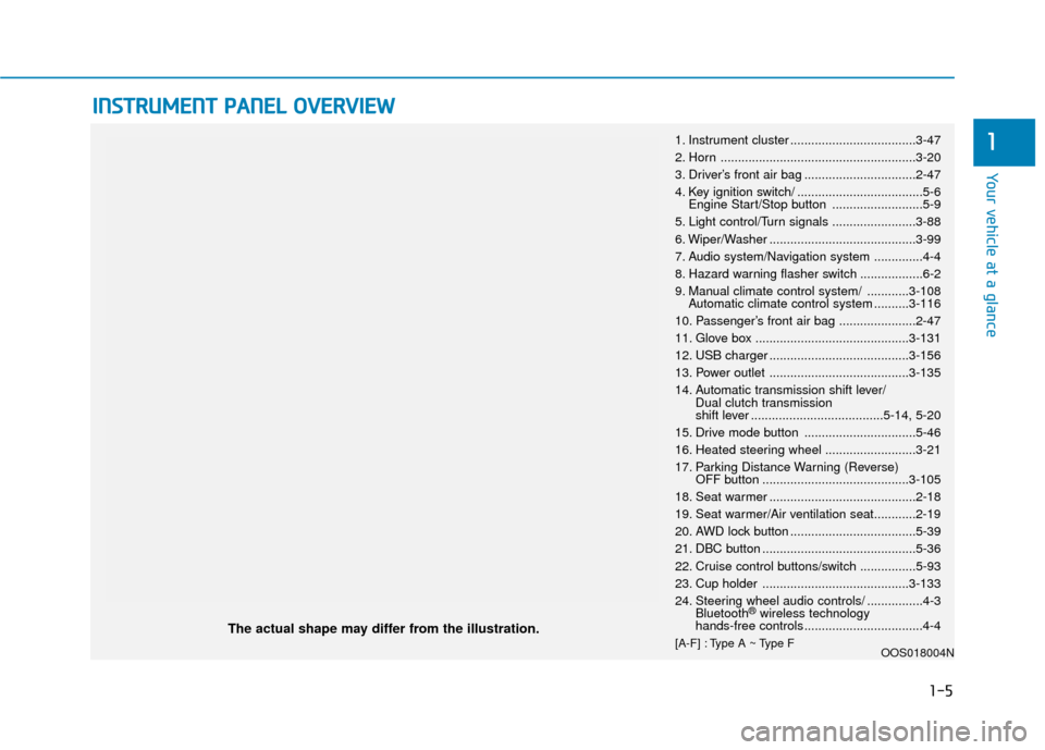
The actual shape may differ from the illustration.
1-5
Your vehicle at a glance
11. Instrument cluster ....................................3-47
2. Horn ........................................................3-20
3. Driver’s front air bag ................................2-47
4. Key ignition switch/ ....................................5-6
Engine Start/Stop button ..........................5-9
5. Light control/Turn signals ........................3-88
6. Wiper/Washer ..........................................3-99
7. Audio system/Navigation system ..............4-4
8. Hazard warning flasher switch ..................6-2
9. Manual climate control system/ ............3-108 Automatic climate control system ..........3-116
10. Passenger’s front air bag ......................2-47
11. Glove box ............................................3-131
12. USB charger ........................................3-156
13. Power outlet ........................................3-135
14. Automatic transmission shift lever/ Dual clutch transmission
shift lever ......................................5-14, 5-20
15. Drive mode button ................................5-46
16. Heated steering wheel ..........................3-21
17. Parking Distance Warning (Reverse) OFF button ..........................................3-105
18. Seat warmer ..........................................2-18
19. Seat warmer/Air ventilation seat............2-19
20. AWD lock button ....................................5-39
21. DBC button ............................................5-36
22. Cruise control buttons/switch ................5-93
23. Cup holder ..........................................3-133
24. Steering wheel audio controls/ ................4-3 Bluetooth
®wireless technology
hands-free controls ..................................4-4
[A-F] : Type A ~ Type F OOS018004N
Page 68 of 485
2-51
Safety system of your vehicle
2
10. Side pressure sensors
11. Seat belt buckle sensor
12. Emergency Fastening DeviceSystem
13. Occupant classification system
The SRSCM (Supplemental Restraint
System Control Module) continually
monitors all SRS components while
the ignition switch is in the ON position
to determine if a crash impact is
severe enough to require air bag
deployment or pre-tensioner seat belt
deployment.SRS warning light
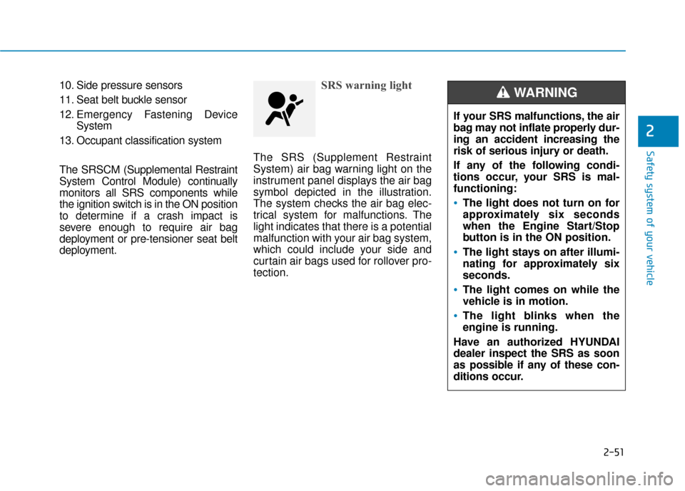
The SRS (Supplement Restraint
System) air bag warning light on the
instrument panel displays the air bag
symbol depicted in the illustration.
The system checks the air bag elec-
trical system for malfunctions. The
light indicates that there is a potential
malfunction with your air bag system,
which could include your side and
curtain air bags used for rollover pro-
tection.
If your SRS malfunctions, the air
bag may not inflate properly dur-
ing an accident increasing the
risk of serious injury or death.
If any of the following condi-
tions occur, your SRS is mal-
functioning:
The light does not turn on for
approximately six seconds
when the Engine Start/Stop
button is in the ON position.
The light stays on after illumi-
nating for approximately six
seconds.
The light comes on while the
vehicle is in motion.
The light blinks when the
engine is running.
Have an authorized HYUNDAI
dealer inspect the SRS as soon
as possible if any of these con-
ditions occur.
WARNING
Page 69 of 485
2-52
Safety system of your vehicle
During a frontal collision, sensors will
detect the vehicle's deceleration. If
the rate of deceleration is high
enough, the control unit will inflate
the front air bags.
The front air bags help protect the
driver and front passenger by
responding to frontal impacts in
which seat belts alone cannot pro-
vide adequate restraint. When need-
ed, the side air bags help provide
protection in the event of a side
impact or rollover.
Air bags are activated (able to inflate if necessary) only when the
Engine Start/Stop button is in the
ON position.
Air bags inflate in the event of cer- tain frontal or side collisions to help
protect the occupants from serious
physical injury.
Generally, air bags are designed to inflate based upon the severity of a
collision, its direction, etc. These
two factors determine whether the
sensors produce an electronic
deployment/inflation signal. The front air bags will completely
inflate and deflate in an instant. It is
virtually impossible for you to see
the air bags inflate during an acci-
dent. It is much more likely that you
will simply see the deflated air bags
hanging out of their storage com-
partments after the collision.
In addition to inflating in certain side collisions, vehicles equipped
with a rollover sensor, side and
curtain air bags will inflate if the
sensing system detects a rollover.
When a rollover is detected, side
and curtain air bags will remain
inflated longer to help provide pro-
tection from ejection, especially
when used in conjunction with the
seat belts. To help provide protection, the air
bags must inflate rapidly. The speed
of air bag inflation is a consequence
of extremely short time in which to
inflate the air bag between the
occupant and the vehicle structures
before the occupant impacts those
structures. This speed of inflation
reduces the risk of serious or life-
threatening injuries and is thus a
necessary part of air bag design.
However, the rapid air bag inflation
can also cause injuries which can
include facial abrasions, bruises
and broken bones because the
inflation speed also causes the air
bags to expand with a great deal of
force.
There are even circumstances under which contact with the air
bag can cause fatal injuries, espe-
cially if the occupant is positioned
excessively close to the air bag.
Page 77 of 485
2-60
Safety system of your vehicle
Proper seated position for OCS
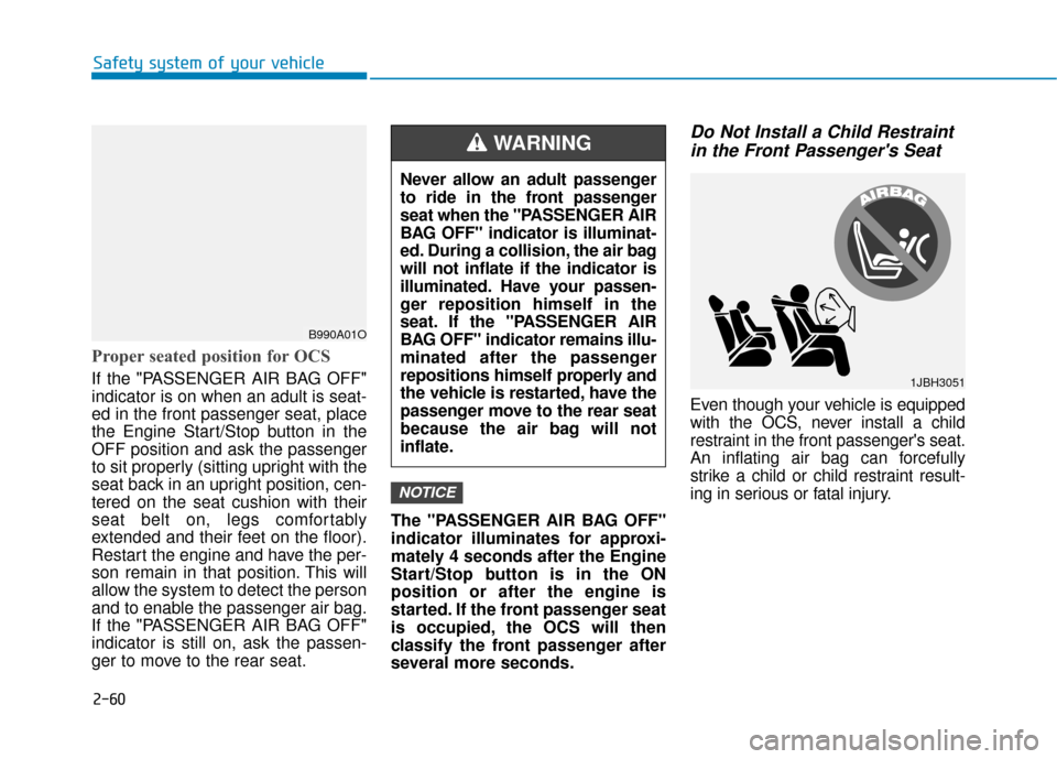
If the "PASSENGER AIR BAG OFF"
indicator is on when an adult is seat-
ed in the front passenger seat, place
the Engine Start/Stop button in the
OFF position and ask the passenger
to sit properly (sitting upright with the
seat back in an upright position, cen-
tered on the seat cushion with their
seat belt on, legs comfortably
extended and their feet on the floor).
Restart the engine and have the per-
son remain in that position. This will
allow the system to detect the person
and to enable the passenger air bag.
If the "PASSENGER AIR BAG OFF"
indicator is still on, ask the passen-
ger to move to the rear seat.The "PASSENGER AIR BAG OFF"
indicator illuminates for approxi-
mately 4 seconds after the Engine
Start/Stop button is in the ON
position or after the engine is
started. If the front passenger seat
is occupied, the OCS will then
classify the front passenger after
several more seconds.
Do Not Install a Child Restraint
in the Front Passenger's Seat
Even though your vehicle is equipped
with the OCS, never install a child
restraint in the front passenger's seat.
An inflating air bag can forcefully
strike a child or child restraint result-
ing in serious or fatal injury.
NOTICE
B990A01O
Never allow an adult passenger
to ride in the front passenger
seat when the "PASSENGER AIR
BAG OFF" indicator is illuminat-
ed. During a collision, the air bag
will not inflate if the indicator is
illuminated. Have your passen-
ger reposition himself in the
seat. If the "PASSENGER AIR
BAG OFF" indicator remains illu-
minated after the passenger
repositions himself properly and
the vehicle is restarted, have the
passenger move to the rear seat
because the air bag will not
inflate.
WARNING
1JBH3051
Page 84 of 485
2-67
Safety system of your vehicle
2
Additional Safety Precautions
Passengers should not move out
of or change seats while the vehi-
cle is moving.A passenger who is
not wearing a seat belt during a
crash or emergency stop can be
thrown against the inside of the vehi-
cle, against other occupants, or be
ejected from the vehicle.
Do not use any accessories on
seat belts. Devices claiming to
improve occupant comfort or reposi-
tion the seat belt can reduce the pro-
tection provided by the seat belt and
increase the chance of serious injury
in a crash. Do not modify the front seats.
Modification of the front seats could
interfere with the operation of the
supplemental restraint system sens-
ing components or side air bags.
Do not place items under the front
seats.
Placing items under the front
seats could interfere with the opera-
tion of the supplemental restraint
system sensing components and
wiring harnesses.
Do not cause impact to the doors.
Impact to the doors when the Engine
Start/Stop button is in the ON posi-
tion may cause the air bags to inflate.
Modifications to accommodate
disabilities. If you require modifica-
tion to your vehicle to accommodate
a disability, contact the HYUNDAI
Customer Connect Center at 800-
633-5151.
Adding equipment to or modify- ing your air bag equipped vehicle
If you modify your vehicle by chang-
ing your vehicle's frame, bumper sys-
tem, front end or side sheet metal or
ride height, this may affect the opera-
tion of your vehicle's air bag system.
Air Bag Warning Labels
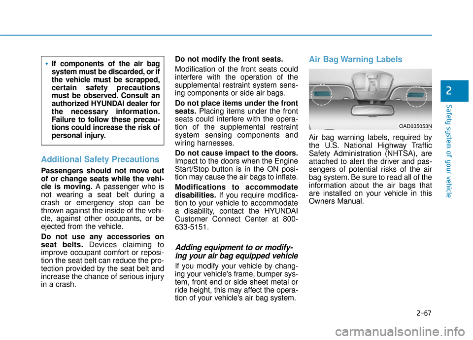
Air bag warning labels, required by
the U.S. National Highway Traffic
Safety Administration (NHTSA), are
attached to alert the driver and pas-
sengers of potential risks of the air
bag system. Be sure to read all of the
information about the air bags that
are installed on your vehicle in this
Owners Manual.
If components of the air bag
system must be discarded, or if
the vehicle must be scrapped,
certain safety precautions
must be observed. Consult an
authorized HYUNDAI dealer for
the necessary information.
Failure to follow these precau-
tions could increase the risk of
personal injury.
OAD035053N
Page 91 of 485
3-7
Convenient features of your vehicle
Locking your vehicle
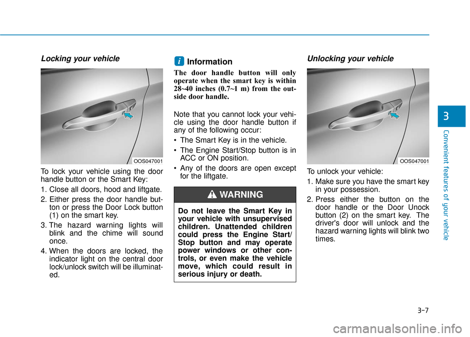
To lock your vehicle using the door
handle button or the Smart Key:
1. Close all doors, hood and liftgate.
2. Either press the door handle but-ton or press the Door Lock button
(1) on the smart key.
3. The hazard warning lights will blink and the chime will sound
once.
4. When the doors are locked, the indicator light on the central door
lock/unlock switch will be illuminat-
ed.
Information
The door handle button will only
operate when the smart key is within
28~40 inches (0.7~1 m) from the out-
side door handle.
Note that you cannot lock your vehi-
cle using the door handle button if
any of the following occur:
The Smart Key is in the vehicle.
The Engine Start/Stop button is inACC or ON position.
Any of the doors are open except for the liftgate.
Unlocking your vehicle
To unlock your vehicle:
1. Make sure you have the smart key in your possession.
2. Press either the button on the door handle or the Door Unock
button (2) on the smart key. The
driver's door will unlock and the
hazard warning lights will blink two
times.
i
3
Do not leave the Smart Key in
your vehicle with unsupervised
children. Unattended children
could press the Engine Start/
Stop button and may operate
power windows or other con-
trols, or even make the vehicle
move, which could result in
serious injury or death.
WARNING
OOS047001OOS047001
Page 93 of 485
3-9
Convenient features of your vehicle
Information
• The liftgate handle button will onlyoperate when the smart key is with-
in 28 inches (0.7 m) from the liftgate
handle.
• The Liftgate Unlock button (3) will only unlock the liftgate. It will not
release the latch and open the lift-
gate automatically. If the Liftgate
Unlock button is used, someone
must still press the liftgate handle
button to open the liftgate.
Panic button
Press and hold the Panic button (4)
for more than one second. The horn
sounds and hazard warning lights
blink for about 30 seconds. To cancel
the panic mode, press any button on
the Smart Key.
Start-up
You can start the vehicle without
inserting the key.
For information, refer to the
"Engine Start/Stop Button" sec-
tion in chapter 5.
To prevent damaging the smart key:
Keep the smart key in a cool, dryplace to avoid damage or mal-
function. Exposure to moisture
or high temperature may cause
the internal circuit of the smart
key to malfunction which may
not be covered under warranty.
Avoid dropping or throwing the smart key.
Protect the smart key from extreme temperatures.
Mechanical key
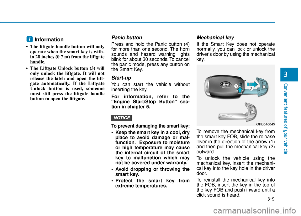
If the Smart Key does not operate
normally, you can lock or unlock the
driver's door by using the mechanical
key.
To remove the mechanical key from
the smart key FOB, slide the release
lever in the direction of the arrow (1)
and then pull the mechanical key (2)
outward.
To unlock the vehicle using the
mechanical key. insert the mechani-
cal key into the key hole in the driver
door.
To reinstall the mechanical key into
the FOB, insert the key in the top of
the key FOB and push inward until a
click sound is heard.
NOTICE
i
3
OPD046045
Page 98 of 485
3-14
Convenient features of your vehicle
If you press the button on the front
passenger's outside door, all doors
will unlock.
Once the doors are unlocked, they
may be opened by pulling the door
handle.
When closing the door, push the
door by hand. Make sure that doors
are closed securely.
Information
• In cold and wet climates, door lock and door mechanisms may not work
properly due to freezing conditions.
• If the door is locked/unlocked multi- ple times in rapid succession with
either the vehicle key or door lock
switch, the system may stop operat-
ing temporarily in order to protect
the circuit and prevent damage to
system components.
• Two press unlock setting can be changed in the User Settings mode
on the cluster.
Operating Door Locks from
Inside the Vehicle
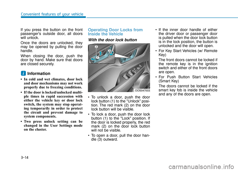
With the door lock button
To unlock a door, push the doorlock button (1) to the "Unlock" posi-
tion. The red mark (2) on the door
lock button will be visible.
To lock a door, push the door lock button (1) to the "Lock" position. If
the door is locked properly, the red
mark (2) on the door lock button
will not be visible.
To open a door, pull the door han- dle (3) outward. If the inner door handle of either
the driver door or passenger door
is pulled when the door lock button
is in the lock position, the button is
unlocked and the door will open.
For Key Start Vehicles (w/ Remote Key)
The front doors cannot be locked if
the remote key is in the ignition
switch and either of the front doors
are open.
For Push Button Start Vehicles (Smart Key)
The doors cannot be locked if the
smart key fob is inside the vehicle
and any of the doors are open.
i
OOS047003
Page 110 of 485
3-26
Convenient features of your vehicle
To adjust the Zone setting:
1. Determine the desired Zone Number based upon your current
location on the Zone Map.
2. Press and hold the Control Button for up to 6 seconds, the current
Zone Number will appear on the
display.
3. Release and press the Control Button and then hold the Control
Button again will cause the num-
bers to increment (Note: they will
repeat …13, 14, 15, 1, 2, …).
Releasing the button when the
desired Zone Number appears on
the display will set the new Zone.
4. Within about 5 seconds the com- pass will start displaying a com-
pass heading again.
There are some conditions that can
cause changes to the vehicle mag-
nets, such as installing a ski rack or
a CB antenna. Body repair work on
the vehicle can also cause changes
to the vehicle's magnetic field. In
these situations, the compass will
need to be re-calibrated to correct
these changes. If you need to recalibrate the com-
pass:
1. Press and hold the Control Button
for more than 6 seconds. When
the compass memory is cleared, a
"C" will appear in the display.
2. Drive the vehicle in 2 complete cir- cles at less than 5 mph (8 km/h).
Integrated HomeLink®Wireless
Control System
The HomeLink®Wireless Control
System can replace up to three
hand-held radio-frequency (RF)
transmitters with a single built-in
device. This innovative feature will
learn the radio frequency codes of
most current transmitters to operate
devices such as gate operators,
garage door openers, entry door
locks, security systems, even home
lighting. Both standard and rolling
code-equipped transmitters can be
programmed by following the out-
lined procedures.
Additional HomeLink
®information
can be found at: www.homelink.com,
www.youtube.com/HomeLinkGentex
or by calling 1-800-355-3515. Retain the original transmitter of the
RF device you are programming for
use in other vehicles as well as for
future HomeLink
®programming. It is
also suggested that upon the sale of
the vehicle, the programmed
HomeLink
®buttons be erased for
security purposes.
Before programming HomeLink
®
to a garage door opener or gate
operator, make sure people and
objects are out of the way of the
device to prevent potential harm
or damage. Do not use the
HomeLink
®with any garage
door opener that lacks the safe-
ty stop and reverse features
required by U.S. federal safety
standards (this includes any
garage door opener model man-
ufactured before April 1, 1982). A
garage door that cannot detect
an object - signaling the door to
stop and reverse - does not meet
current U.S. federal safety stan-
dards. Using a garage door
opener without these features
increases the risk of serious
injury or death.
WARNING
Page 123 of 485
3-39
Convenient features of your vehicle
3
Periodically remove any dirt thatmay accumulate on the sunroof
guide rail or between the sun-
roof and roof panel which can
make a noise.
Do not try to open the sunroof when the temperature is below
freezing or when the sunroof is
covered with snow or ice, other-
wise the motor could be dam-
aged. In cold and wet climates,
the sunroof may not work prop-
erly.
Sunshade
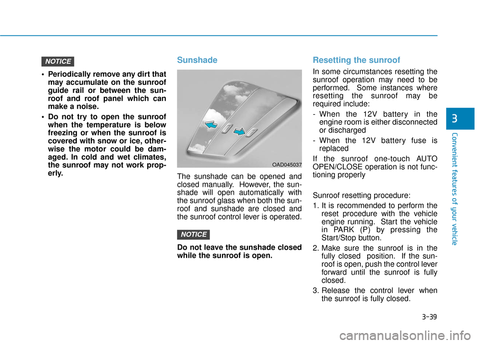
The sunshade can be opened and
closed manually. However, the sun-
shade will open automatically with
the sunroof glass when both the sun-
roof and sunshade are closed and
the sunroof control lever is operated.
Do not leave the sunshade closed
while the sunroof is open.
Resetting the sunroof
In some circumstances resetting the
sunroof operation may need to be
performed. Some instances where
resetting the sunroof may be
required include:
- When the 12V battery in theengine room is either disconnected
or discharged
- When the 12V battery fuse is replaced
If the sunroof one-touch AUTO
OPEN/CLOSE operation is not func-
tioning properly
Sunroof resetting procedure:
1. It is recommended to perform the reset procedure with the vehicle
engine running. Start the vehicle
in PARK (P) by pressing the
Start/Stop button.
2. Make sure the sunroof is in the fully closed position. If the sun-
roof is open, push the control lever
forward until the sunroof is fully
closed.
3. Release the control lever when the sunroof is fully closed.
NOTICE
NOTICE
OAD045037