unit change Hyundai Kona 2019 Owner's Manual
[x] Cancel search | Manufacturer: HYUNDAI, Model Year: 2019, Model line: Kona, Model: Hyundai Kona 2019Pages: 485, PDF Size: 15.75 MB
Page 135 of 485
3-51
Convenient features of your vehicle
3
Outside temperature gauge
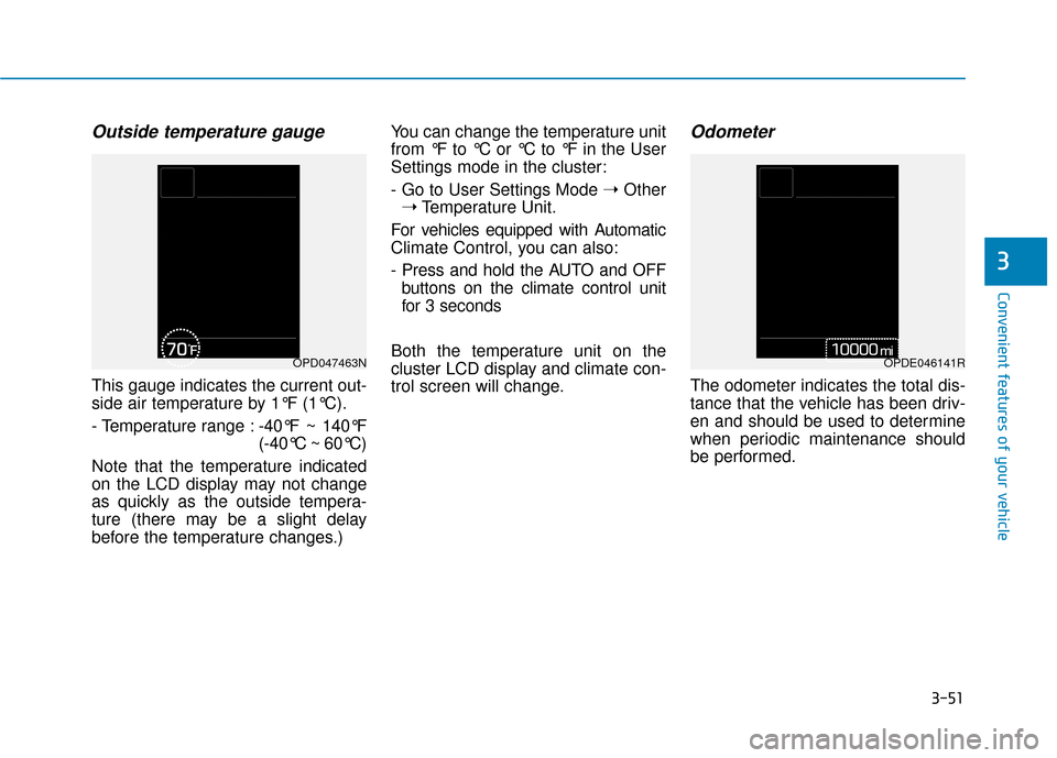
This gauge indicates the current out-
side air temperature by 1°F (1°C).
- Temperature range :-40°F ~ 140°F
(-40°C ~ 60°C)
Note that the temperature indicated
on the LCD display may not change
as quickly as the outside tempera-
ture (there may be a slight delay
before the temperature changes.) You can change the temperature unit
from °F to °C or °C to °F in the User
Settings mode in the cluster:
- Go to User Settings Mode
➝Other
➝ Temperature Unit.
For vehicles equipped with Automatic
Climate Control, you can also:
- Press and hold the AUTO and OFF buttons on the climate control unit
for 3 seconds
Both the temperature unit on the
cluster LCD display and climate con-
trol screen will change.
Odometer
The odometer indicates the total dis-
tance that the vehicle has been driv-
en and should be used to determine
when periodic maintenance should
be performed.
OPD047463NOPDE046141R
Page 177 of 485
3-93
Convenient features of your vehicle
3
Turn signals and lane changesignals
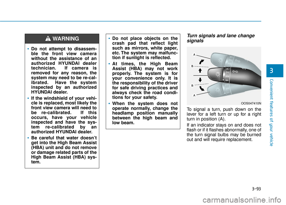
To signal a turn, push down on the
lever for a left turn or up for a right
turn in position (A).
If an indicator stays on and does not
flash or if it flashes abnormally, one of
the turn signal bulbs may be burned
out and will require replacement.
OOS047410N
Do not attempt to disassem-
ble the front view camera
without the assistance of an
authorized HYUNDAI dealer
technician. If camera is
removed for any reason, the
system may need to be re-cal-
ibrated. Have the system
inspected by an authorized
HYUNDAI dealer.
If the windshield of your vehi-
cle is replaced, most likely the
front view camera will need to
be re-calibrated. If this
occurs, have your vehicle
inspected and have the sys-
tem re-calibrated by an
authorized HYUNDAI dealer.
Be careful that water doesn’t
get into the High Beam Assist
(HBA) unit and do not remove
or damage related parts of the
High Beam Assist (HBA) sys-
tem.
Do not place objects on the
crash pad that reflect light
such as mirrors, white paper,
etc. The system may malfunc-
tion if sunlight is reflected.
At times, the High Beam
Assist (HBA) may not work
properly. The system is for
your convenience only. It is
the responsibility of the driver
for safe driving practices and
always check the road condi-
tions for your safety.
When the system does not
operate normally, change the
headlamp position manually
between the high beam and
low beam.
WARNING
Page 201 of 485
3-117
Convenient features of your vehicle
3
Automatic Temperature
Control Mode
The Automatic Climate Control
System is controlled by setting the
desired temperature.
1. Press the AUTO button (3).
The modes, fan speeds, air intake
and air-conditioning will be controlled
automatically by the temperature set-
ting you select.
2. Turn the temperature control knob(1) to the desired temperature. If
the temperature is set to the low-
est setting (Lo), the air condition-
ing system will operate continu-
ously. After the interior has cooled
sufficiently, adjust the knob to a
higher temperature set point
whenever possible.
To turn the automatic operation off,
select any button of the following: - Mode selection button
- Front windshield defroster button(Press the button one more time
to deselect the front windshield
defroster function. The 'AUTO'
sign will illuminate on the infor-
mation display once again.)
- Fan speed control button The selected function will be con-
trolled manually while other functions
operate automatically.
For your convenience and to improve
the efficiency of the climate control,
use the AUTO button and set the
temperature to 73°F (23°C).
To change the temperature unit from
°F to °C or °C to °F:
Press and hold the AUTO and OFF
buttons on the climate control unit for
3 seconds.
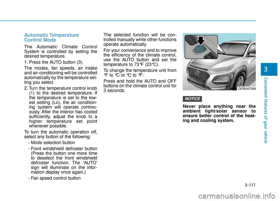
Never place anything near the
ambient light/solar sensor to
ensure better control of the heat-
ing and cooling system.
NOTICE
OOS047308
Page 221 of 485
3-137
Convenient features of your vehicle
3
To charge a cellular phone
The wireless cellular phone charging
system charges only the Qi-enabled
cellular phones ( ). Read the label
on the cellular phone accessory
cover or visit your cellular phone
manufacturer's website to check
whether your cellular phone supports
the Qi technology.
The wireless charging process starts
when you put a Qi-enabled cellular
phone on the wireless charging unit.
1. Remove other items, including thesmart key, from the wireless
charging unit. If not, the wireless
charging process may be inter-
rupted. Place the cellular phone
on the center of the charging pad.
2. The indicator light is orange when the cellular phone is charging. The
indicator light turns green when
phone charging is complete.
3. You can turn ON or OFF the wire- less charging function in the user
settings mode on the instrument
cluster. For further information,
refer to the "LCD Display Modes"
in this chapter. If your cellular phone is not charging:
- Slightly change the position of the
cellular phone on the charging pad.
- Make sure the indicator light is orange.
The indicator light will blink orange
for 10 seconds if there is a malfunc-
tion in the wireless charging system.
In this case, temporarily stop the
charging process, and re-attempt to
charge your cellular phone again.
The system warns you with a mes-
sage on the LCD display if the cellu-
lar phone is still on the wireless
charging unit after the engine is
turned OFF and the front door is
opened.
Information
For some manufacturer's cellular
phones, the system may not warn you
even though the cellular phone is left
on the wireless charging unit. This is
due to the particular characteristic of
the cellular phone and not a malfunc-
tion of the wireless charging. The wireless cellular phone
charging system may not sup-
port certain cellular phones,
which are not verified for the Qi
specification ( ).
When placing your cellular phone on the charging mat,
position the phone in the middle
of the mat for optimal charging
performance. If your cell phone
is off to the side, the charging
rate may be less and in some
cases the cell phone may experi-
ence higher heat conduction.
In some cases, the wireless charging may stop temporarily
when the Smart Key is used,
either when starting the vehicle
or locking/unlocking the doors,
etc.
When charging certain cellular phones, the charging indicator
may not change to green when
the cell phone is fully charged.
NOTICE
i
Page 350 of 485
6-8
What to do in an emergency
T
TI
IR
R E
E
P
P R
R E
ES
SS
SU
U R
RE
E
M
M O
ON
NI
IT
T O
O R
RI
IN
N G
G
S
S Y
Y S
ST
T E
EM
M
(
( T
T P
P M
M S
S)
)
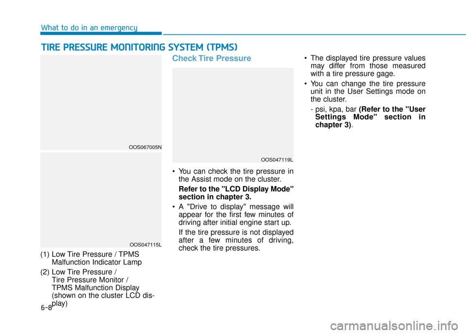
(1) Low Tire Pressure / TPMS
Malfunction Indicator Lamp
(2) Low Tire Pressure / Tire Pressure Monitor /
TPMS Malfunction Display
(shown on the cluster LCD dis-
play)
Check Tire Pressure
You can check the tire pressure inthe Assist mode on the cluster.
Refer to the "LCD Display Mode"
section in chapter 3.
A "Drive to display" message will appear for the first few minutes of
driving after initial engine start up.
If the tire pressure is not displayed
after a few minutes of driving,
check the tire pressures. The displayed tire pressure values
may differ from those measured
with a tire pressure gage.
You can change the tire pressure unit in the User Settings mode on
the cluster.
- psi, kpa, bar (Refer to the "User
Settings Mode" section in
chapter 3).
OOS047115L
OOS067005N
OOS047119L
Page 380 of 485
7-8
Maintenance
I : Inspect and if necessary, adjust, correct, clean or replace.
R : Replace or change.
*
1: The drive belt should be replaced when cracks occur or tension is reduced excessively.
*2: If TOP TIER Detergent Gasoline is not available, one bottle of additive is recommended. Additives are available from your authorized HYUNDAI dealer along with information on how to use them. Do not mix other additives.
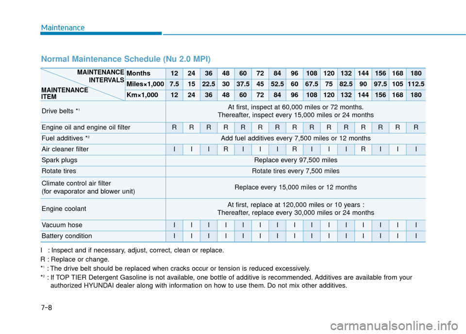
Normal Maintenance Schedule (Nu 2.0 MPI)
Months1224364860728496108120132144156168180
Miles×1,0007.51522.53037.54552.56067.57582.59097.5105112.5
Km×1,0001224364860728496108120132144156168180
Drive belts *1At first, inspect at 60,000 miles or 72 months.
Thereafter, inspect every 15,000 miles or 24 months
Engine oil and engine oil filterRRRRRRRRRRRRRRR
Fuel additives *2Add fuel additives every 7,500 miles or 12 months
Air cleaner filterIIIRIIIRIIIRIII
Spark plugsReplace every 97,500 miles
Rotate tiresRotate tires every 7,500 miles
Climate control air filter
(for evaporator and blower unit)Replace every 15,000 miles or 12 months
Engine coolantAt first, replace at 120,000 miles or 10 years :
Thereafter, replace every 30,000 miles or 24 months
Vacuum hoseIIIIIIIIIIIIIII
Battery conditionIIIIIIIIIIIIIII
MAINTENANCE
INTERVALS
MAINTENANCE
ITEM
Page 385 of 485
7-13
7
Maintenance
I : Inspect and if necessary, adjust, correct, clean or replace.
R : Replace or change.
*
1: The drive belt should be replaced when cracks occur or tension is reduced excessively.
*2: If TOP TIER Detergent Gasoline is not available, one bottle of additive is recommended. Additives are available from your authorized HYUNDAI dealer along with information on how to use them. Do not mix other additives.
*
3: Inspect for excessive valve noise and/or engine vibration and adjust if necessary. Have an authorized HYUNDAI dealer per- form the operation.
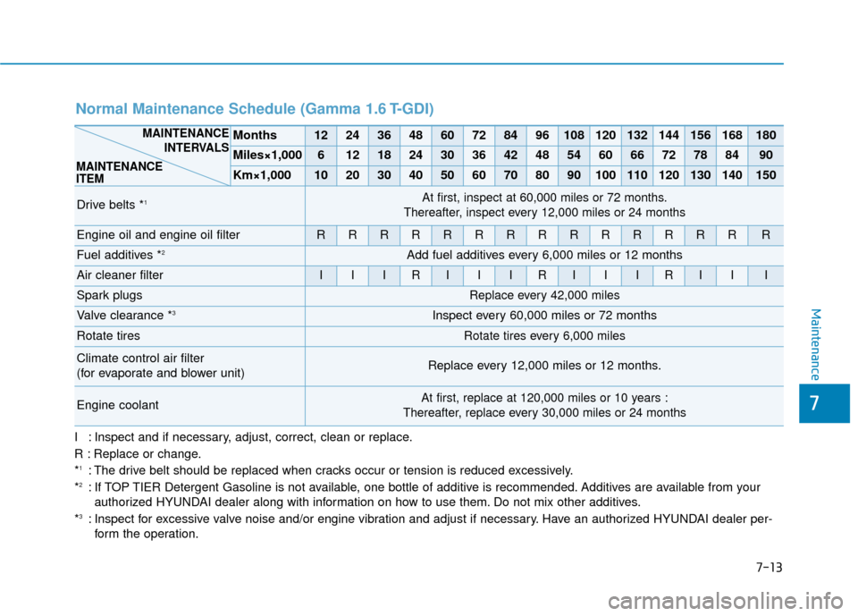
Normal Maintenance Schedule (Gamma 1.6 T-GDI)
Months1224364860728496108120132144156168180
Miles×1,00061218243036424854606672788490
Km×1,000102030405060708090100110120130140150
Drive belts *1At first, inspect at 60,000 miles or 72 months.
Thereafter, inspect every 12,000 miles or 24 months
Engine oil and engine oil filterRRRRRRRRRRRRRRR
Fuel additives *2Add fuel additives every 6,000 miles or 12 months
Air cleaner filterIIIRIIIRIIIRIII
Spark plugsReplace every 42,000 miles
Valve clearance *3Inspect every 60,000 miles or 72 months
Rotate tiresRotate tires every 6,000 miles
Climate control air filter
(for evaporate and blower unit)Replace every 12,000 miles or 12 months.
Engine coolantAt first, replace at 120,000 miles or 10 years :
Thereafter, replace every 30,000 miles or 24 months
MAINTENANCE INTERVALS
MAINTENANCE
ITEM