tow Hyundai Kona 2020 User Guide
[x] Cancel search | Manufacturer: HYUNDAI, Model Year: 2020, Model line: Kona, Model: Hyundai Kona 2020Pages: 505, PDF Size: 13.47 MB
Page 135 of 505
3-51
Convenient features of your vehicle
3
Gauges and Meters
Speedometer
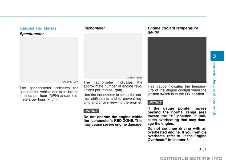
The speedometer indicates the
speed of the vehicle and is calibrated
in miles per hour (MPH) and/or kilo-
meters per hour (km/h).
Tachometer
The tachometer indicates the
approximate number of engine revo-
lutions per minute (rpm).
Use the tachometer to select the cor-
rect shift points and to prevent lug-
ging and/or over-revving the engine.
Do not operate the engine within
the tachometer's RED ZONE. This
may cause severe engine damage.
Engine coolant temperaturegauge
This gauge indicates the tempera-
ture of the engine coolant when the
ignition switch is in the ON position.
If the gauge pointer moves
beyond the normal range area
toward the "H" position, it indi-
cates overheating that may dam-
age the engine.
Do not continue driving with an
overheated engine. If your vehicle
overheats, refer to "If the Engine
Overheats" in chapter 6.
NOTICE
NOTICE
OOS047103N
OOS047104L
OOS047140L
Page 176 of 505
3-92
Convenient features of your vehicle
High beam operation
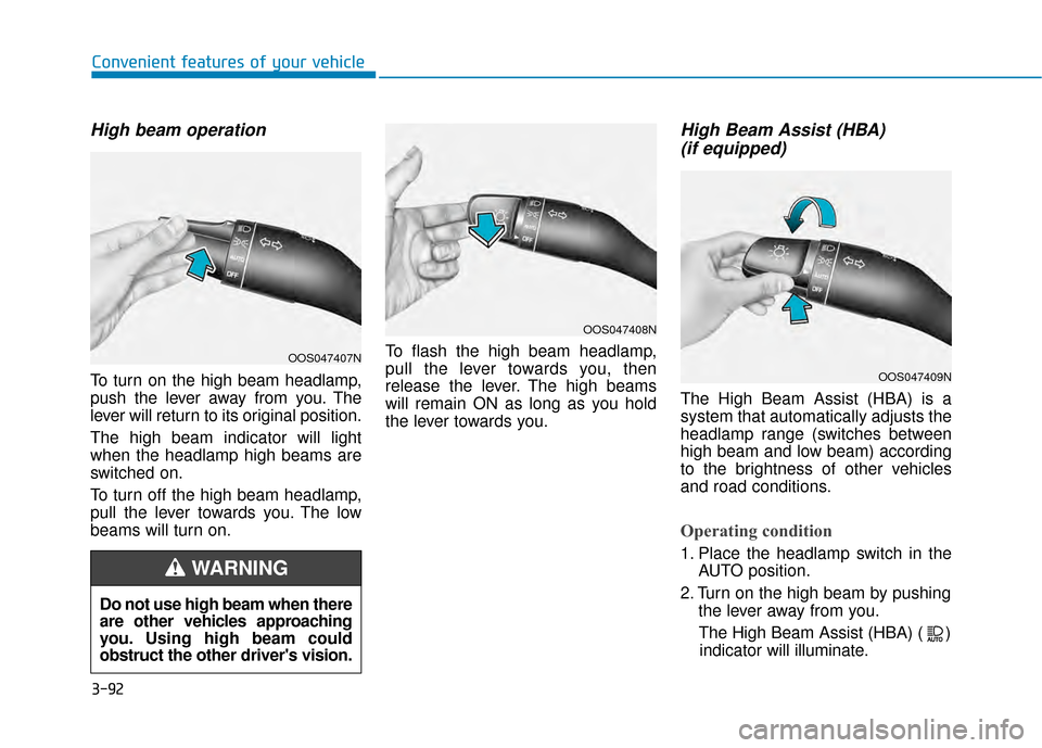
To turn on the high beam headlamp,
push the lever away from you. The
lever will return to its original position.
The high beam indicator will light
when the headlamp high beams are
switched on.
To turn off the high beam headlamp,
pull the lever towards you. The low
beams will turn on.To flash the high beam headlamp,
pull the lever towards you, then
release the lever. The high beams
will remain ON as long as you hold
the lever towards you.
High Beam Assist (HBA)
(if equipped)
The High Beam Assist (HBA) is a
system that automatically adjusts the
headlamp range (switches between
high beam and low beam) according
to the brightness of other vehicles
and road conditions.
Operating condition
1. Place the headlamp switch in the
AUTO position.
2. Turn on the high beam by pushing the lever away from you.
The High Beam Assist (HBA) ( ) indicator will illuminate.
Do not use high beam when there
are other vehicles approaching
you. Using high beam could
obstruct the other driver's vision.
WARNING
OOS047407N
OOS047408N
OOS047409N
Page 177 of 505
3-93
Convenient features of your vehicle
3
3. The High Beam Assist (HBA) willturn on when vehicle speed is
above 25 mph (40 km/h).
away when the High Beam Assist
(HBA) is operating, the High Beam
Assist (HBA) will turn off and the
high beam will be on continuously.
the headlamp switch is pulled
towards you when the high beam
is off, the high beam will turn on
without the High Beam Assist
(HBA) canceled. When you let go
of the light switch, the lever will
move to the middle and the high
beam will turn off.
the headlamp switch is pulled
towards you when the high beam
is on by the High Beam Assist
(HBA), the low beam will be on
and the High Beam Assist (HBA)
will turn off.
to the headlamp ON position, the
High Beam Assist (HBA) will turn
off and the low beam will be on
continuously. When the High Beam Assist (HBA) is
operating, the high beam switches to
low beamif any of the following condi-
tions occur :
- When the headlamp of an on-com-
ing vehicle is detected.
- When the tail lamp of a vehicle in front is detected.
- When the headlamp or tail lamp of a motorcycle or a bicycle is detect-
ed.
- When the surrounding ambient light is bright enough that high beams
are not required.
- When streetlights or other lights are detected.
- When the headlamp s witch is not in
the AUTO position.
- When the High Beam Assist (HBA) is off.
- When vehicle speed is below 22mph (35 km/h).
Warning light and message
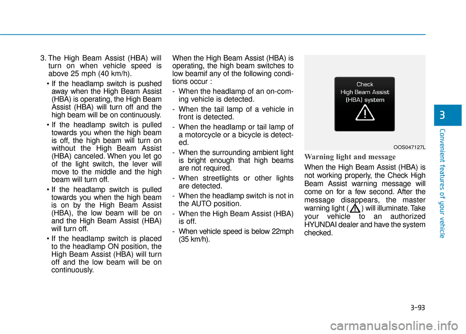
When the High Beam Assist (HBA) is
not working properly, the Check High
Beam Assist warning message will
come on for a few second. After the
message disappears, the master
warning light ( ) will illuminate. Take
your vehicle to an authorized
HYUNDAI dealer and have the system
checked.
OOS047127L
Page 178 of 505
3-94
Convenient features of your vehicleThe system may not operate nor-
mally if any of the following con-
ditions should occur:
1) When the illumination from an on-coming vehicle or a
vehicle in front is dim. Such
examples may include:
When the headlamps of an on-
coming vehicle or the tail
lamps of a vehicle in front is
covered with dust, snow, or
water.
When the headlamps on an on-
coming vehicle are OFF, but the
fog lamps are ON.
2) When the High Beam Assist camera is adversely affected
by an external condition.
Such examples may include:
When the vehicle's head-
lamps have been damaged or
not repaired properly.
When the vehicle headlamps
are not aimed properly.
When the vehicle is driven on
a narrow curved road or rough
road
When the vehicle is driven on
an uphill road or downhill
road
When only part of the vehicle in
front is visible on a crossroad
or curved road.
When there is a traffic light,
reflecting sign, flashing sign or
mirror.
When the road conditions are
bad such as being wet or cov-
ered with snow.
When a vehicle suddenly
appears from a curve.
When the vehicle is tilted from
a flat tire or being towed.
When the Lane Keeping Assist
(LKA) system warning light
illuminates.
When the light from the on-
coming or front vehicle is not
detected because of exhaust
fume, smoke, fog, snow, etc.
When the front window is cov-
ered with foreign matters such
as ice, dust, fog, or is damaged.
3) When the forward visibility is poor. Such examples may
include:
When the headlamps of an on-
coming vehicle or a vehicle in
front is not detected due to
poor outside visibility (smog,
smoke, dust, fog, heavy rain,
snow, etc.).
When the windshield visibility
is poor.
WARNING
Page 185 of 505
3-101
Convenient features of your vehicle
3
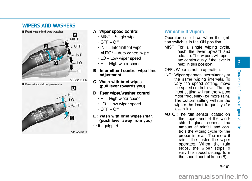
A : Wiper speed control· MIST – Single wipe
· OFF – Off
· INT – Intermittent wipeAUTO* – Auto control wipe
· LO – Low wiper speed
· HI – High wiper speed
B : Intermittent control wipe time adjustment
C : Wash with brief wipes (pull lever towards you)
D : Rear wiper/washer control · HI – High wiper speed
· LO – Low wiper speed
· OFF – Off
E : Wash with brief wipes (rear) (push lever away from you)
* : if equippedWindshield Wipers
Operates as follows when the igni-
tion switch is in the ON position.
MIST : For a single wiping cycle,
push the lever upward and
release. The wipers will oper-
ate continuously if the lever is
held in this position.
OFF : Wiper is not in operation.
INT : Wiper operates intermittently at the same wiping intervals. To
vary the speed setting, move
the speed control lever. The top
most setting will run the wipers
most frequently (for more rain).
The bottom setting will run the
wipers the least frequently (for
less rain).
AUTO : The rain sensor located on the upper end of the wind-
shield glass senses the
amount of rainfall and con-
trols the wiping cycle for the
proper interval. The more it
rains, the faster the wiper
operates. When the rain
stops, the wiper stops.To
vary the speed setting, turn
the speed control knob (B).
W WI
IP
P E
ER
R S
S
A
A N
N D
D
W
W A
AS
SH
H E
ER
R S
S
OPD047454L
OTLA045318
■ Front windshield wiper/washer
■Rear windshield wiper/washer
Page 187 of 505
3-103
Convenient features of your vehicle
3
Windshield Washers
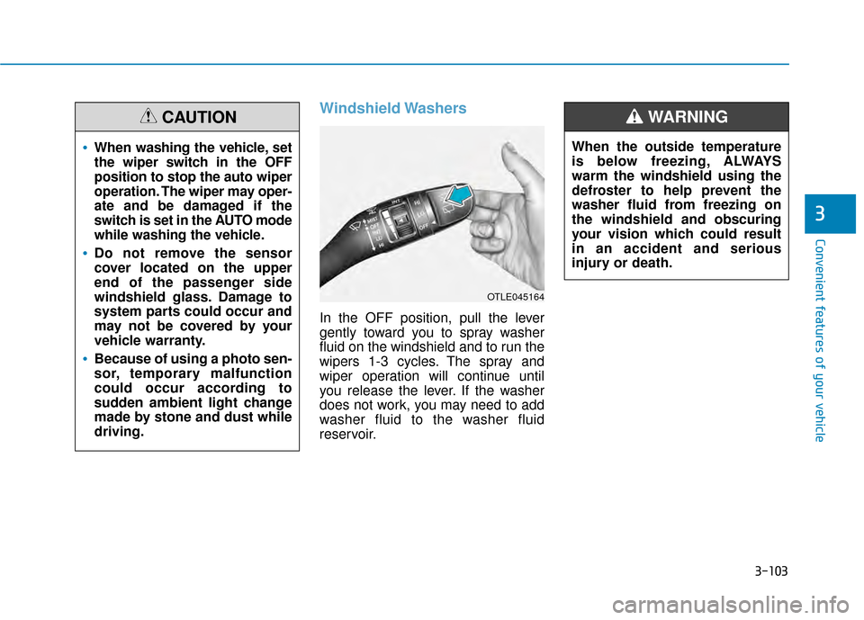
In the OFF position, pull the lever
gently toward you to spray washer
fluid on the windshield and to run the
wipers 1-3 cycles. The spray and
wiper operation will continue until
you release the lever. If the washer
does not work, you may need to add
washer fluid to the washer fluid
reservoir.When the outside temperature
is below freezing, ALWAYS
warm the windshield using the
defroster to help prevent the
washer fluid from freezing on
the windshield and obscuring
your vision which could result
in an accident and serious
injury or death.
WARNING
OTLE045164
When washing the vehicle, set
the wiper switch in the OFF
position to stop the auto wiper
operation. The wiper may oper-
ate and be damaged if the
switch is set in the AUTO mode
while washing the vehicle.
Do not remove the sensor
cover located on the upper
end of the passenger side
windshield glass. Damage to
system parts could occur and
may not be covered by your
vehicle warranty.
Because of using a photo sen-
sor, temporary malfunction
could occur according to
sudden ambient light change
made by stone and dust while
driving.
CAUTION
Page 196 of 505
3-112
Convenient features of your vehicle
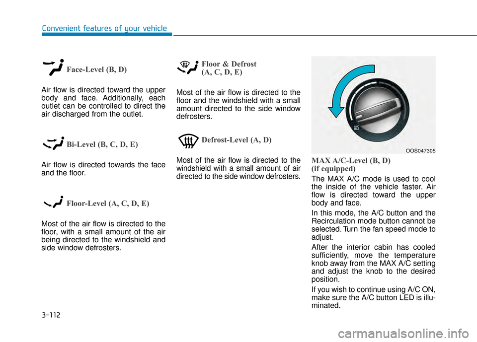
Face-Level (B, D)
Air flow is directed toward the upper
body and face. Additionally, each
outlet can be controlled to direct the
air discharged from the outlet.
Bi-Level (B, C, D, E)
Air flow is directed towards the face
and the floor.
Floor-Level (A, C, D, E)
Most of the air flow is directed to the
floor, with a small amount of the air
being directed to the windshield and
side window defrosters.
Floor & Defrost
(A, C, D, E)
Most of the air flow is directed to the
floor and the windshield with a small
amount directed to the side window
defrosters.
Defrost-Level (A, D)
Most of the air flow is directed to the
windshield with a small amount of air
directed to the side window defrosters.MAX A/C-Level (B, D)
(if equipped)
The MAX A/C mode is used to cool
the inside of the vehicle faster. Air
flow is directed toward the upper
body and face.
In this mode, the A/C button and the
Recirculation mode button cannot be
selected. Turn the fan speed mode to
adjust.
After the interior cabin has cooled
sufficiently, move the temperature
knob away from the MAX A/C setting
and adjust the knob to the desired
position.
If you wish to continue using A/C ON,
make sure the A/C button LED is illu-
minated.
OOS047305
Page 205 of 505
3-121
Convenient features of your vehicle
3
The air flow outlet direction is cycled
as follows:
Face-Level (B, D)
Air flow is directed toward the upper
body and face. Additionally, each
outlet can be controlled to direct the
air discharged from the outlet.
Bi-Level (B, C, D, E)
Air flow is directed towards the face
and the floor.
Floor & Defrost
(A, C, D, E)
Most of the air flow is directed to the
floor and the windshield with a small
amount directed to the side window
defrosters.
Floor-Level (A, C, D, E)
Most of the air flow is directed to the
floor, with a small amount of the air
being directed to the windshield and
side window defrosters.
Defrost-Level (A, D) (6)
Most of the air flow is directed to the
windshield with a small amount of air
directed to the side window defrosters.
Instrument panel vents
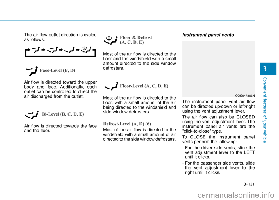
The instrument panel vent air flow
can be directed up/down or left/right
using the vent adjustment lever.
The air flow can also be CLOSED
using the vent adjustment lever. The
instrument panel air vents are the
"click-to-close" type.
To CLOSE the instrument panel
vents perform the following:
- For the driver side vents, slide thevent adjustment lever to the LEFT
until it clicks.
- For the passenger side vents, slide the vent adjustment lever to the
right until it clicks.
OOS047306N
Page 220 of 505
3-136
Convenient features of your vehicle
Keep your drinks sealed while driving to prevent spilling your
drink. If liquid spills, it may get
into the vehicle's electrical/elec-
tronic system and damage elec-
trical/electronic parts.
When cleaning spilled liquids do not use hot air to blow out or dry
the cup holder. This may dam-
age the interior.
Sunvisor
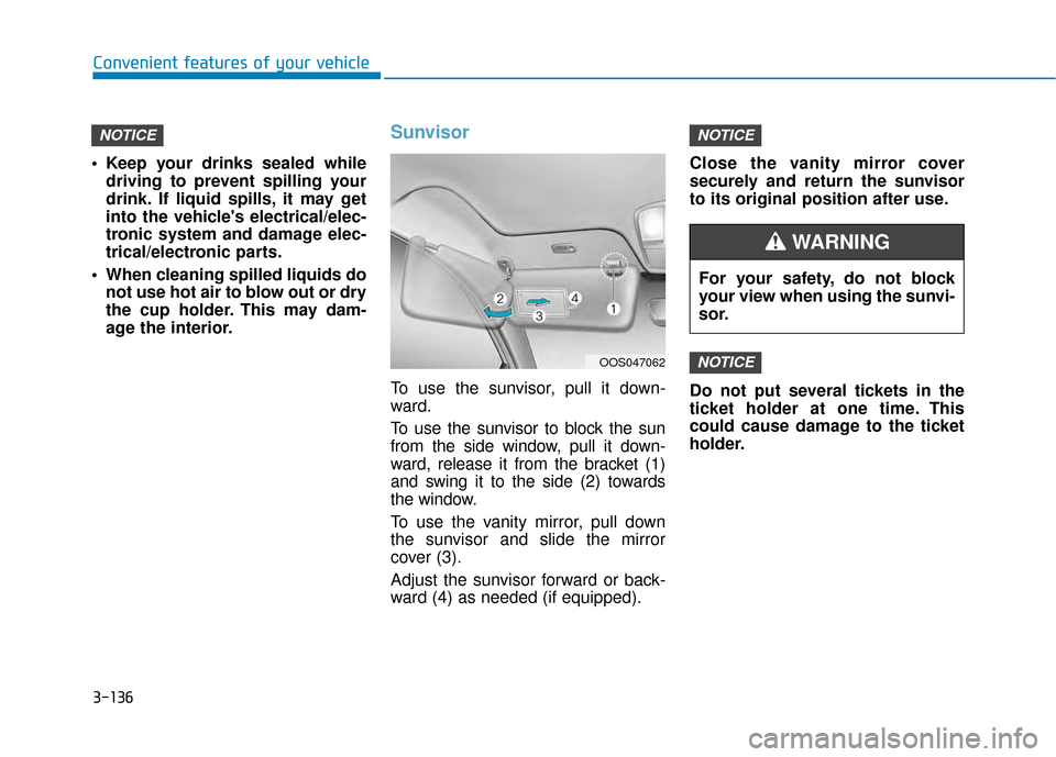
To use the sunvisor, pull it down-
ward.
To use the sunvisor to block the sun
from the side window, pull it down-
ward, release it from the bracket (1)
and swing it to the side (2) towards
the window.
To use the vanity mirror, pull down
the sunvisor and slide the mirror
cover (3).
Adjust the sunvisor forward or back-
ward (4) as needed (if equipped). Close the vanity mirror cover
securely and return the sunvisor
to its original position after use.
Do not put several tickets in the
ticket holder at one time. This
could cause damage to the ticket
holder.
NOTICE
NOTICENOTICE
OOS047062
For your safety, do not block
your view when using the sunvi-
sor.
WARNING
Page 236 of 505
5
Lane Keeping Assist (LKA) system ...................5-80
LKA system Operation ...................................................5-81
Warning Light and Message.........................................5-85
Limitations of the System .............................................5-86
LKA system Function Change ......................................5-87
Driver Attention Warning (DAW) system .........5-88
System Setting and Activation.....................................5-88
Resetting the System .....................................................5-89
System Standby ...............................................................5-90
System Malfunction .......................................................5-90
Cruise Control .......................................................5-92
Cruise Control operation ...............................................5-92
Smart Cruise Control system..............................5-97
Smart Cruise Control Switch ........................................5-97
Smart Cruise Control Speed .........................................5-98
Smart Cruise Control Vehicle-to-Vehicle
Distance ........................................................................\
...5-102
Sensor to Detect Distance to the Vehicle Ahead ..5-105
SCC Reaction Setting ...................................................5-107
Conventional Cruise Control Mode ...........................5-108
Limitations of the System...........................................5-108
Special Driving Conditions ................................5-114
Hazardous Driving Conditions....................................5-114
Rocking the Vehicle ......................................................5-114
Smooth Cornering .........................................................5-115
Driving at Night .............................................................5-115
Driving in the Rain ........................................................5-115
Driving in Flooded Areas.............................................5-116
Highway Driving ............................................................5-116
Reducing the risk of a rollover .................................5-117
Winter driving .....................................................5-118
Snow or Icy Conditions................................................5-118
Winter Precautions .......................................................5-120
Vehicle load limit ................................................5-122
Tire Loading Information Label .................................5-123
Trailer towing .....................................................5-127