engine Hyundai Matrix 2004 Manual Online
[x] Cancel search | Manufacturer: HYUNDAI, Model Year: 2004, Model line: Matrix, Model: Hyundai Matrix 2004Pages: 317, PDF Size: 5.12 MB
Page 172 of 317
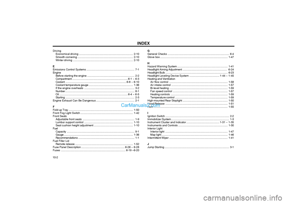
INDEX
10-2 Driving
Economical dr iving ........................................................................ 2-10
Smooth cornering .......................................................................... 2-10
Winter driving ................................................................................ 2-10
E Emissions Control Systems ................................................................ 7-1
Engine Before starting the engine ............................................................... 2-2Compartment .......................................................................... 6-1 ~ 6-3
Coolant ................................................................................. 6-8 ~ 6-10
Coolant temperature gauge ........................................................... 1-36
If the engine overheats ................................................................... 3-2
Number ............................................................................................ 8-1
Oil ........................................................................................... 6-4 ~ 6-5Starting ............................................................................................ 2-3
Engine Exhaust Can Be Dangerous ................................................... 2-1
FFold-up Tray ...................................................................................... 1-50
Front Fog Light Sw itch ...................................................................... 1-42
Front Seats Adjustable front seats ..................................................................... 1-9
Lumbar support control ................................................................. 1-10
Seat cushion height adjustment .................................................... 1-10
Fuel Capacity .......................................................................................... 9-1
Gauge ............................................................................................ 1-36
Recommendations ........................................................................... 1-1
Fuel Filler Lid
Remote release ............................................................................. 1-52
Fuse Panel Description .......................................................... 6-26 ~ 6-28
Fuses ...................................................................................... 6-19 ~6-20 GGeneral Checks
.................................................................................. 6-4
Glove box .......................................................................................... 1-47
H Hazard Warning System ................................................................... 1-41
Headlight Aiming Adjustment ........................................................... 6-24
Headlight Bulb ................................................................................... 6-23
Headlight Leveling Device System ........................................ 1-44 ~ 1-45
Heating and Ventilation
Air flow control .............................................................................. 1-58
Air intake control ........................................................................... 1-57
Bi-level heating .............................................................................. 1-59
Fan speed control ......................................................................... 1-57
Heating controls ............................................................................ 1-59
Temperature control ...................................................................... 1-59
High-mounted Rear Stoplight ............................................................ 1-50
Hood Release ................................................................................... 1-51
Horn .................................................................................................. 1-55
IIgnition Switch ..................................................................................... 2-2
Immobilizer System ............................................................................. 1-3
Instrument Cluster and Indicator ............................................ 1-31 ~ 1-35
Instruments and Controls .................................................................. 1-30
Interior Light Interior light ................................................................................... 1-47
Map light ........................................................................................ 1-46
Intermittent Wiper .............................................................................. 1-41
JJump Starting ...................................................................................... 3-1
Page 178 of 317
SA030A1-EFOREWORD
Hyundai Motor Company wish to take this opportunity to thank you for purchasing a Hyundai product and to welcome you to the ever increasing number of discriminating motorists who drive Hyundai vehicles. The advanced engineeringand construction methods employed during both design and production of the Hyundai marque are something ofwhich we are proud, and this commitment to providing a high quality product is supported by a comprehensive aftersales and warranty service of which we are equally proud. This owners manual will introduce the operating and maintenance requirements for the vehicle and it is recommended that it is carefully read to ensure that the maximum performance and durability along with safe and satisfactory operationare obtained. The recommended routine maintenance servicing along with any running repairs that may be required should be entrusted to a franchised Hyundai dealer to ensure that only the latest methods and genuine Hyundai replacement parts are used for the continued reliability, safety and performance of the vehicle. Should any question or query exist regarding any aspect of your Hyundai please contact the nearest Hyundai dealer who will be only too pleased to assist wherever possible. Note: This owners manual should be considered as part of the vehicle and should be kept in the vehicle at all times for
ease of reference. In the event of the vehicle being sold please ensure that this manual is left in the vehicle for the reference of the new owner. CAUTION: Severe engine and transaxle damage may result from the use of poor quality fuels and lubricants that do not meet Hyundai specifications. You must always use high quality fuels and lubricants that meet thespecifications listed on Page 9-3 in the Vehicle Specifications section of the Owner's Manual. Copyright 2003 Hyundai Motor Company. All rights reserved. No part of this publication may be reproduced, stored in any
retrieval system or transmitted in any form or by any means without the prior written permission of Hyundai Motor Company.
fcuk-0.p65 3/6/2007, 9:55 AM
4
Page 182 of 317

A100A01L-EAT Guide to Hyundai Genuine Parts
1. What are Hyundai Genuine Parts?Hyundai Genuine Parts are the same parts used by Hyundai Motor Company to man- ufacture vehicles. They are designed and tested for the optimum safety, performance, and reliability to our customers.
2. Why should you use genuine parts? Hyundai Genuine Parts are engineeredand built to meet rigid original manufactur- ing requirements. Using imitation, counter- feit or used salvage parts is not covered under the Hyundai New Vehicle Limited Warranty or any other Hyundai warranty. In addition, any damage to or failure ofGenuine Hyundai Parts caused by the installation or failure of an imitation, coun- terfeit or used salvage part is not covered by Hyundai Motor Company.
3. How can you tell if you are purchasing Hyundai Genuine Parts? Look for the Hyundai Genuine Parts Logoon the package (see below). The export specifications are written in English only. Hyundai Genuine Parts are only sold through authorized Hyundai Dealerships.
A100A01LA100A02LA100A04L
A100A03L
fcuk-0.p65
3/6/2007, 9:55 AM
8
Page 183 of 317
1- 1
CONTROLS AND EQUIPMENT
from jerry cans or by means of a funnel that the fuel being used is unleaded.The use of leaded fuel in this vehicle will result in irreversible pollution of the catalyst ele- ment. Such pollution will prevent correct op- eration of the catalyst and give rise to in- creased operating temperatures leading to the catalyst element melting and restricting the exhaust flow along with an increase in exhaust emission levels. CAUTION: The vehicle warranty will not extend to damage arising from the use of incorrect fuels. Use Diesel Diesel fuel of 52 to 54 cetane is the correct rating to use in Hyundai vehicle. If two types of diesel fuel are available, use summer or winter fuel properly according to the following temperature conditions.
o Above 23°F (-5°C) ... Summer type diesel fuel.
o Below 23°F (-5°C) ... Winter type diesel fuel. Watch the fuel level in the tank very carefully: If the engine stops through fuel failure, thecircuits must be completely purged to permit restarting.
SB000A1-E 1
. CONTROLS AND
EQUIPMENT
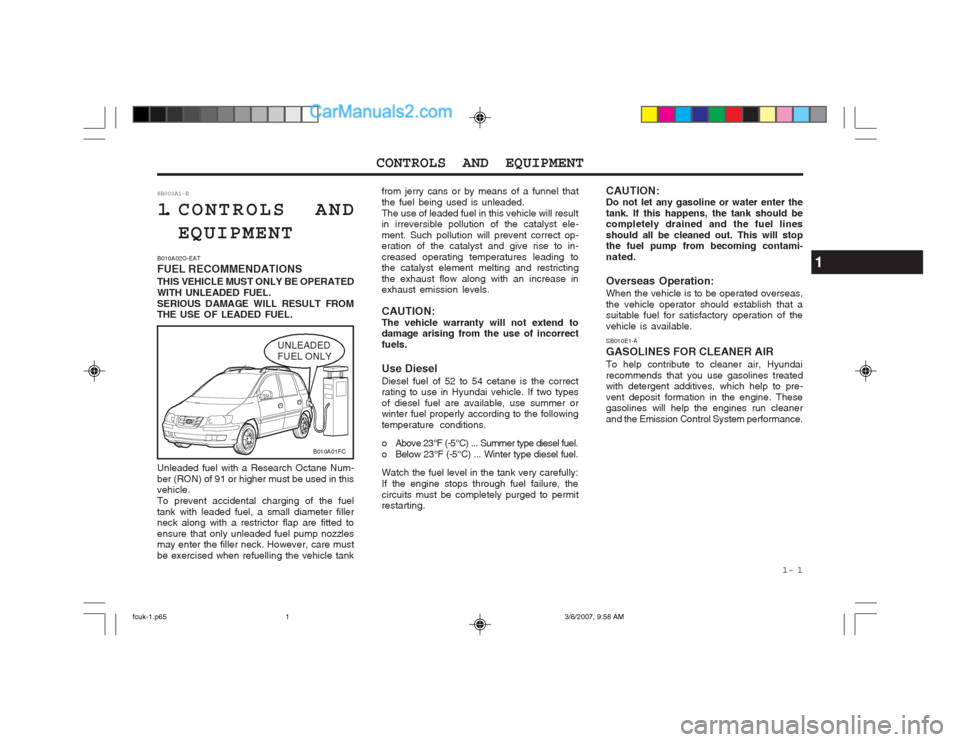
B010A02O-EAT FUEL RECOMMENDATIONSTHIS VEHICLE MUST ONLY BE OPERATED WITH UNLEADED FUEL.SERIOUS DAMAGE WILL RESULT FROM THE USE OF LEADED FUEL.
UNLEADED FUEL ONLY
Unleaded fuel with a Research Octane Num-ber (RON) of 91 or higher must be used in this vehicle. To prevent accidental charging of the fueltank with leaded fuel, a small diameter filler neck along with a restrictor flap are fitted to ensure that only unleaded fuel pump nozzles may enter the filler neck. However, care must be exercised when refuelling the vehicle tank SB010E1-A GASOLINES FOR CLEANER AIRTo help contribute to cleaner air, Hyundai recommends that you use gasolines treated with detergent additives, which help to pre- vent deposit formation in the engine. These gasolines will help the engines run cleaner and the Emission Control System performance.
CAUTION:Do not let any gasoline or water enter thetank. If this happens, the tank should be completely drained and the fuel lines should all be cleaned out. This will stop the fuel pump from becoming contami- nated. Overseas Operation: When the vehicle is to be operated overseas, the vehicle operator should establish that a suitable fuel for satisfactory operation of the vehicle is available.
1
B010A01FC
fcuk-1.p65
3/6/2007, 9:58 AM
1
Page 184 of 317
CONTROLS AND EQUIPMENT
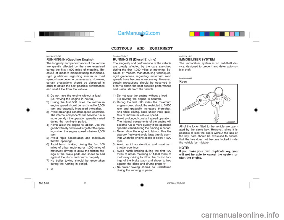
1- 2 6SB035A1-FE IMMOBILISER SYSTEMThe immobiliser system is an anti-theft de- vice, designed to prevent and deter automo- bile theft. B880B03A-GAT Keys All of the locks fitted to the vehicle are oper- ated by the same key. However, since it is possible to lock the doors without the use of the key, care should be exercised to ensure that the key does not become locked inside the vehicle by mistake. NOTE: If you make your own duplicate key, youwill not be able to cancel the system or start the engine.
B020A02FC-EAT RUNNING IN (Gasoline Engine)The longevity and performance of the vehicle are greatly affected by the care exercised during the first 1,000 miles of motoring. Be- cause of modern manufacturing techniques, rigid guidelines regarding maximum road speeds have become unnecessary. However, certain precautions should be observed in order to obtain the best possible performance and useful life from the vehicle.
1) Do not race the engine without a load
(i.e revving the engine in neutral).
2) During the first 500 miles the maximum engine speed should be restricted to 3,000 rpm and gradually increased thereafter.
3) Avoid prolonged constant speed operation. The internal components will become run in
more quickly if the operation speed is varied
during the running-in period.
4) Never allow the engine to labour. Use the gearbox freely and avoid large throttle open-ings when the engine speed is below 1,500 rpm.
5) Avoid rapid acceleration and maximum throttle openings.
6) Avoid harsh braking during the first 100 miles of urban motoring or 1,000 miles ofmotorway driving to allow the friction fac- ings of the brake pads and shoes to bed against the discs and drums properly.
7) No trailer towing should be undertaken during the running in period.
AX10020A-1
B020B02FC-EAT RUNNING IN (Diesel Engine)The longevity and performance of the vehicle are greatly affected by the care exercised during the first 1,000 miles of motoring. Be- cause of modern manufacturing techniques, rigid guidelines regarding maximum road speeds have become unnecessary. However, certain precautions should be observed in order to obtain the best possible performance and useful life from the vehicle.
1) Do not race the engine without a load
(i.e revving the engine in neutral).
2) During the first 600 miles the maximum engine speed should be restricted to 3,000 rpm and gradually increased thereafter. And while driving, keep under three quar- ters of maximum vehicle speed.
3) Avoid prolonged constant speed operation. The internal components of the engine will
become run in more quickly if the operation speed is varied during the running in period.
4) Never allow the engine to labour. Use the gearbox freely and avoid large throttle open-ings when the engine speed is below 1,500 rpm.
5) Avoid rapid acceleration and maximum throttle openings.
6) Avoid harsh braking during the first 100 miles of urban motoring or 1,000 miles ofmotorway driving to allow the friction fac- ings of the brake pads and shoes to bed against the discs and drums properly.
7) No trailer towing should be undertaken during the running in period.
fcuk-1.p65 3/6/2007, 9:58 AM
2
Page 187 of 317
1- 5
CONTROLS AND EQUIPMENT
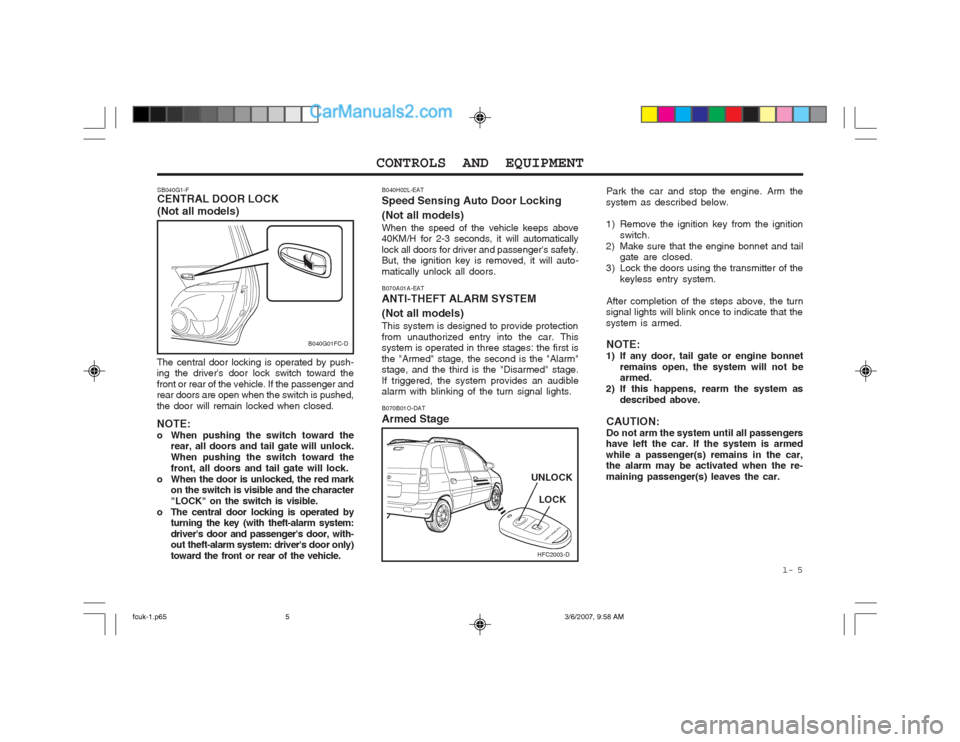
SB040G1-F CENTRAL DOOR LOCK (Not all models)
The central door locking is operated by push- ing the driver's door lock switch toward the front or rear of the vehicle. If the passenger and rear doors are open when the switch is pushed, the door will remain locked when closed. NOTE:
o When pushing the switch toward the rear, all doors and tail gate will unlock.When pushing the switch toward thefront, all doors and tail gate will lock.
o When the door is unlocked, the red mark on the switch is visible and the character"LOCK" on the switch is visible.
o The central door locking is operated by turning the key (with theft-alarm system:driver's door and passenger's door, with- out theft-alarm system: driver's door only) toward the front or rear of the vehicle. B070A01A-EAT ANTI-THEFT ALARM SYSTEM (Not all models) This system is designed to provide protection from unauthorized entry into the car. This system is operated in three stages: the first is the "Armed" stage, the second is the "Alarm" stage, and the third is the "Disarmed" stage. If triggered, the system provides an audible alarm with blinking of the turn signal lights.
HFC2003-D
LOCK
UNLOCK
B040G01FC-D
B070B01O-DAT Armed Stage Park the car and stop the engine. Arm the
system as described below.
1) Remove the ignition key from the ignition
switch.
2) Make sure that the engine bonnet and tail gate are closed.
3) Lock the doors using the transmitter of the keyless entry system.
After completion of the steps above, the turn
signal lights will blink once to indicate that the system is armed.
NOTE:
1) If any door, tail gate or engine bonnet remains open, the system will not be armed.
2) If this happens, rearm the system as described above.
CAUTION: Do not arm the system until all passengers
have left the car. If the system is armedwhile a passenger(s) remains in the car, the alarm may be activated when the re- maining passenger(s) leaves the car.
B040H02L-EAT Speed Sensing Auto Door Locking (Not all models) When the speed of the vehicle keeps above 40KM/H for 2-3 seconds, it will automatically lock all doors for driver and passenger's safety. But, the ignition key is removed, it will auto- matically unlock all doors.
fcuk-1.p65
3/6/2007, 9:58 AM
5
Page 188 of 317
CONTROLS AND EQUIPMENT
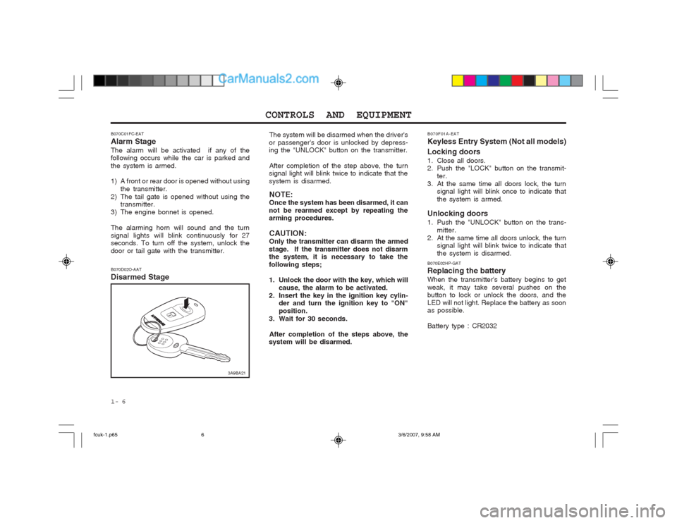
1- 6 The system will be disarmed when the driver's
or passenger's door is unlocked by depress- ing the "UNLOCK" button on the transmitter.
After completion of the step above, the turn
signal light will blink twice to indicate that the system is disarmed.
NOTE:Once the system has been disarmed, it can
not be rearmed except by repeating the arming procedures.
CAUTION: Only the transmitter can disarm the armed
stage. If the transmitter does not disarm the system, it is necessary to take the following steps;
1. Unlock the door with the key, which will
cause, the alarm to be activated.
2. Insert the key in the ignition key cylin- der and turn the ignition key to "ON" position.
3. Wait for 30 seconds.
After completion of the steps above, the
system will be disarmed. B070F01A-EAT Keyless Entry System (Not all models) Locking doors
1. Close all doors.
2. Push the "LOCK" button on the transmit-
ter.
3. At the same time all doors lock, the turn signal light will blink once to indicate that the system is armed.
Unlocking doors
1. Push the "UNLOCK" button on the trans- mitter.
2. At the same time all doors unlock, the turn signal light will blink twice to indicate that the system is disarmed.
B070E02HP-GAT Replacing the battery When the transmitter's battery begins to get weak, it may take several pushes on the button to lock or unlock the doors, and the LED will not light. Replace the battery as soon as possible. Battery type : CR2032
B070C01FC-EAT Alarm StageThe alarm will be activated if any of the following occurs while the car is parked and the system is armed.
1) A front or rear door is opened without using
the transmitter.
2) The tail gate is opened without using the transmitter.
3) The engine bonnet is opened. The alarming horn will sound and the turn signal lights will blink continuously for 27 seconds. To turn off the system, unlock the door or tail gate with the transmitter.
B070D02O-AAT Disarmed Stage
3A9BA21
fcuk-1.p65 3/6/2007, 9:58 AM
6
Page 194 of 317
CONTROLS AND EQUIPMENT
1- 12 o Objects should not extend higher than
the top of the front seatbacks. This could allow cargo to slide forward and cause injury or damage during sudden stops.
o When you return the folded down
seatback to its upright position, alwaysbe sure to install the headrests in their proper positions. Headrests are impor- tant to the safety of occupants in a rear collision. If the headrests are not in- stalled in their proper position, serious injury or death could result if a rear end collision occurs.
B100A01FC-EAT SEAT WARMER (Not all models)
The seat warmer is provided to warm the front seats during cold weather. When the engine is running, push either of the switches to warm the driver's seat or the passenger's seat.
B100A01FC
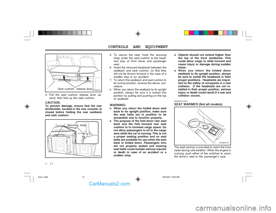
5. To secure the seat, hook the securing strap under the seat cushion to the head- rest stay of front driver and passenger seat.
6. Insert the removed headrests between the seatback and seat cushion, so that theywill not be thrown forward in the case of a sudden stop or an accident.
7. To return the seatback and seat cushion to its normal position, reverse the above pro- cedure.
o When you return the seatback to its upright position, always be sure it is locked intoposition by pulling and pushing on the top of seatback.
WARNING:
o When you return the folded down seat back to its upright position, make surethe seat belts are in position to be accessible and to function properly.
o The purpose of the fold down rear seat back and the fold forward rear seatcushion is to increase cargo space. Do not allow passengers to sit in the cargo area while the car is moving. This is not a proper seating position and no seat belts are available for use when the seat back is folded down. Passengers who are not properly seated and wearing seat belts could sustain serious injuries or death in case of an accident or a sudden stop.
CAUTION: To prevent damage, ensure that the rear drinkholder, located in the rear console, is closed before folding the rear seatback and seat cushion.
4. Pull the seat cushion release lever up-
ward, then fold up the seat cushion.
HFC2075
HFC2076
Seat cushion release lever
Securing strap
fcuk-1.p65 3/6/2007, 9:58 AM
12
Page 205 of 317
1- 23
CONTROLS AND EQUIPMENT
Passenger's Airbag
B240B04FC-D
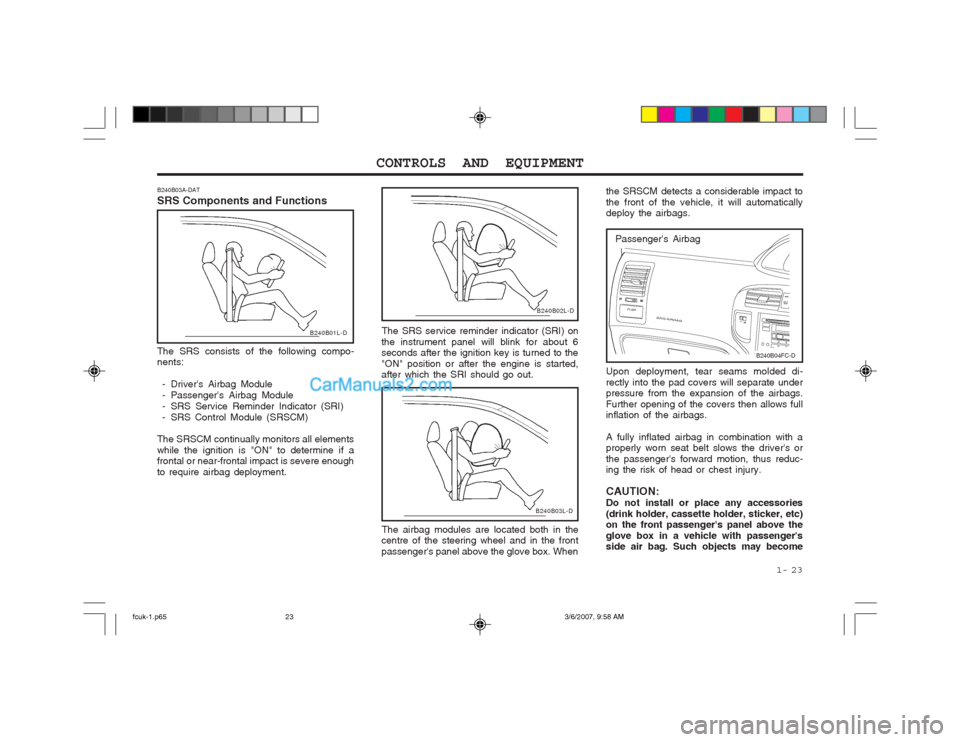
Upon deployment, tear seams molded di- rectly into the pad covers will separate under pressure from the expansion of the airbags. Further opening of the covers then allows full inflation of the airbags. A fully inflated airbag in combination with a properly worn seat belt slows the driver's or the passenger's forward motion, thus reduc- ing the risk of head or chest injury. CAUTION: Do not install or place any accessories(drink holder, cassette holder, sticker, etc) on the front passenger's panel above the glove box in a vehicle with passenger's side air bag. Such objects may become
the SRSCM detects a considerable impact to the front of the vehicle, it will automatically deploy the airbags.
B240B02L-D
The SRS service reminder indicator (SRI) on
the instrument panel will blink for about 6 seconds after the ignition key is turned to the "ON" position or after the engine is started, after which the SRI should go out.
B240B03L-D
The airbag modules are located both in the
centre of the steering wheel and in the front passenger's panel above the glove box. When
B240B03A-DAT SRS Components and Functions
B240B01L-D
The SRS consists of the following compo- nents:
- Driver's Airbag Module
- Passenger's Airbag Module
- SRS Service Reminder Indicator (SRI)
- SRS Control Module (SRSCM)
The SRSCM continually monitors all elementswhile the ignition is "ON" to determine if a frontal or near-frontal impact is severe enough to require airbag deployment.
fcuk-1.p65 3/6/2007, 9:58 AM
23
Page 206 of 317
CONTROLS AND EQUIPMENT
1- 24
WARNING:
o When the SRS is activated, there may be a loud noise and fine dust will be released throughout the vehicle. These conditions are normal and are not haz- ardous. However, the fine dust generat- ed during airbag deployment may cause skin irritation. Be sure to wash your hands and face thoroughly with luke- warm water and a mild soap after an accident in which the airbags were de- ployed.
o The SRS can function only when the ignition key is in the "ON" position. If the SRS SRI does not come on, or continuously remains on, after flashing for about 6 seconds when the ignition key is turned to the "ON" position, or after the engine is started, or comes on while driving, the SRS is not working properly. If this occurs, have your ve- hicle immediately inspected by your Hyundai dealer.
o Before you replace a fuse or disconnect a battery terminal, turn the ignition keyto the "LOCK" position or remove the ignition key. Never remove or replace the air bag related fuse(s) when the ignition key is in the "ON" position. Failure to heed this warning will cause the SRS SRI to illuminate.
Passenger's Airbag
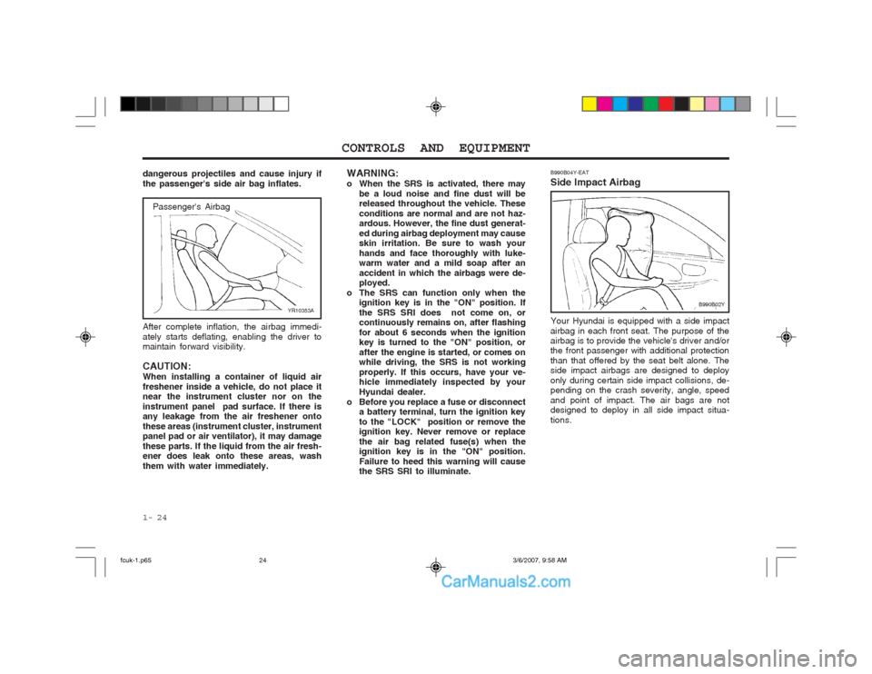
After complete inflation, the airbag immedi- ately starts deflating, enabling the driver to maintain forward visibility. CAUTION: When installing a container of liquid airfreshener inside a vehicle, do not place it near the instrument cluster nor on the instrument panel pad surface. If there is any leakage from the air freshener onto these areas (instrument cluster, instrument panel pad or air ventilator), it may damage these parts. If the liquid from the air fresh- ener does leak onto these areas, wash them with water immediately. YR10353A
dangerous projectiles and cause injury ifthe passenger's side air bag inflates.
B990B04Y-EAT Side Impact Airbag
Your Hyundai is equipped with a side impact
airbag in each front seat. The purpose of the airbag is to provide the vehicle's driver and/orthe front passenger with additional protection than that offered by the seat belt alone. The side impact airbags are designed to deploy only during certain side impact collisions, de- pending on the crash severity, angle, speed and point of impact. The air bags are not designed to deploy in all side impact situa- tions. B990B02Y
fcuk-1.p65
3/6/2007, 9:58 AM
24